

Page 1
Rev. 1.1
Assembly Instructions - Spray Valve SMS-13
Page 1 of 26
Walther Systemtechnik GmbH – D 76726 Germersheim
Telefon: +49 (0)7274-7022-0 Telefax: +49 (0)7274-7022-91
http://www.walther-2000.de – info@walther-2000.de
NOTE
Please read the Assembly Instructions carefully before first using the incomplete device and
strictly adhere to the instructions!
The incomplete device may only be worked with and worked on by persons who are familiar
with the assembly instructions and the current regulations for industrial safety and accident
prevention.
Assembly Instructions
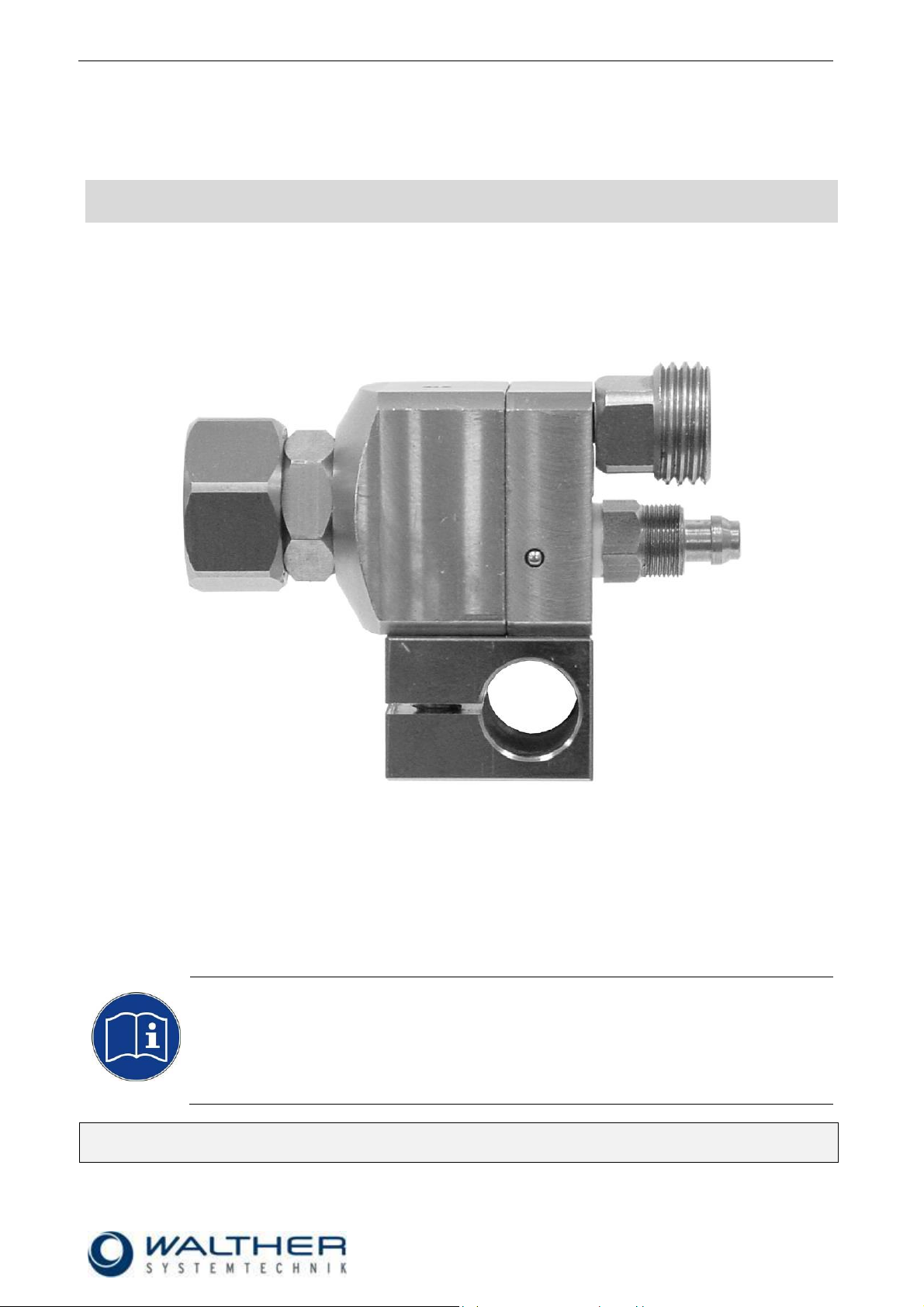
Airless-Spray Valve SMS-13
Article Number: S13-….
Figure: Airless-Spray Valve SMS-13 with clamp (optional)
Keep a translated version of the original Assembly Instructions at a safe place close to the device!
The instructions must be available at all times!
Page 2

Rev. 1.1
Assembly Instructions - Spray Valve SMS-13
Page 2 of 26
Walther Systemtechnik GmbH – D 76726 Germersheim
Telefon: +49 (0)7274-7022-0 Telefax: +49 (0)7274-7022-91
http://www.walther-2000.de – info@walther-2000.de
Table of Contents
Page
EC DECLARATION OF INCORPORATION ....................................................................................................................... 3
1 INTRODUCTION ................................................................................................................................................. 4
1.1 TARGET GROUP OF THE ASSEMBLY INSTRUCTIONS ............................................................................................................ 4
1.2 LIST OF SIGNS AND SYMBOLS ....................................................................................................................................... 4
2 SAFETY............................................................................................................................................................... 4
2.1 GENERAL INFORMATION ............................................................................................................................................. 4
2.2 DANGERS FROM RESIDUAL ENERGY ............................................................................................................................... 4
2.3 WARRANTY AND LIABILITY ........................................................................................................................................... 4
2.4 CORRECT USE ........................................................................................................................................................... 5
2.5 INCORRECT USE ........................................................................................................................................................ 5
2.6 QUALIFICATION OF PERSONNEL .................................................................................................................................... 5
3 TRANSPORT ....................................................................................................................................................... 6
3.1 PACKAGING .............................................................................................................................................................. 6
3.2 TASKS BEFORE TRANSPORT .......................................................................................................................................... 6
4 DESCRIPTION OF FUNCTION .............................................................................................................................. 6
4.1 PURPOSE OF THE DEVICE ............................................................................................................................................. 6
4.2 TECHNICAL DATA ....................................................................................................................................................... 6
4.3 TYPE LABEL .............................................................................................................................................................. 7
5 INSTALLATION AND START-UP ............................................................................................................................ 7
5.1 HOSE MOUNTING...................................................................................................................................................... 7
6 OPERATION ....................................................................................................................................................... 8
6.1 GENERAL INFORMATION ............................................................................................................................................. 8
6.2 OPERATION INSTRUCTIONS / OPERATING CONDITIONS ...................................................................................................... 8
7 TAKING OUT OF SERVICE ................................................................................................................................... 9
7.1 SHORT INTERRUPTION ................................................................................................................................................ 9
7.2 LONG-TERM INTERRUPTION ......................................................................................................................................... 9
7.3 SHUTDOWN OF DEVICE ............................................................................................................................................... 9
8 MAINTENANCE AND REPAIR ............................................................................................................................ 10
8.1 GENERAL INFORMATION ........................................................................................................................................... 10
8.2 CLEANING .............................................................................................................................................................. 10
8.3 INSTALLATION AND REPLACEMENT OF A NOZZLE NEEDLE ................................................................................................. 10
8.4 INSTALLATION AND REPLACEMENT OF AN AIRLESS-NOZZLE .............................................................................................. 10
8.5 INSERTING NEW SEALING ELEMENTS............................................................................................................................ 11
8.6 SPARE PARTS .......................................................................................................................................................... 11
8.7 CUSTOMER SERVICE / SUPPORT .................................................................................................................................. 11
9 TROUBLESHOOTING ........................................................................................................................................ 11
9.1 GENERAL INFORMATION ........................................................................................................................................... 11
9.2 MALFUNCTIONS: ..................................................................................................................................................... 11
10 APPENDIX ........................................................................................................................................................ 12
10.1 DIMENSIONED DRAWING FOR SMS-13 .................................................................................................................. 12
10.1.1 Spare Part Drawing for SMS-13 ............................................................................................................ 13
10.1.2 Spare Part List for SMS-13 .................................................................................................................... 14
10.2 WEAR PARTS KITS ............................................................................................................................................... 14
10.3 AIRLESS-NOZZLES ............................................................................................................................................... 15
10.4 ACCESSORIES ..................................................................................................................................................... 26
Page 3

Rev. 1.1
Assembly Instructions - Spray Valve SMS-13
Page 3 of 26
Walther Systemtechnik GmbH – D 76726 Germersheim
Telefon: +49 (0)7274-7022-0 Telefax: +49 (0)7274-7022-91
http://www.walther-2000.de – info@walther-2000.de
EC Declaration of Incorporation
in accordance with EU Machinery Directive 2006/42/EU, dated 17 May 2006, Appendix II B
We herewith confirm that the below mentioned incomplete device meets the basic requirements for safety
and health as stated in EU Machinery Directive 2006/42/EU for its design and construction as well as for the
configuration released by us on the market. This machine component will not be operated before it has been
determined that the incomplete system where the machine component will be installed also meets the
requirements of the Directive (2006/42/EG).
Manufacturer
Walther Systemtechnik GmbH
Hockenheimer Straße 3
D- 76726 Germersheim
Description
Airless-Spray Valve SMS-13, Article No. S13-……
We also declare the conformity with other, product-relevant directives/guidelines:
Mach. Direct. 2006/42/EU App. I, Clause: 1.1.2, 1.1.3, 1.1.5, 1.1.6, 1.3.2, 1.3.3,
1.3.4, 1.5.8, 1.5.9
Applied harmonized standards, in particular:
DIN EN ISO 12100 Safety of Machinery – General Design Principles –
Risk Assessment and Risk Reduction (ISO
12100:2010)
In addition, we also confirm that the special documentation according to Appendix VII Part B has
been prepared.
The manufacturer, respectively his authorized representative obligates himself to submit this documentation
to the market surveillance authorities, if requested.
This EC Declaration of Incorporation becomes invalid if the incomplete device will be altered or changed
without consent of Walther Systemtechnik GmbH.
Authorized representative for Technical Documentation:
Stefan Hirl, Hockenheimer Straße 3, D- 76726 Germersheim
Germersheim, 20 February 2018
(Place, Date) (Stefan Hirl, Management)
Page 4
Rev. 1.1
Assembly Instructions - Spray Valve SMS-13
Page 4 of 26
Walther Systemtechnik GmbH – D 76726 Germersheim
Telefon: +49 (0)7274-7022-0 Telefax: +49 (0)7274-7022-91
http://www.walther-2000.de – info@walther-2000.de
DANGER
Describes a potentially dangerous situation.
Death, grievous bodily harm or severe material damage WILL occur if the respective
measures of precaution have not been taken
WARNING
Describes a potentially dangerous situation.
Death, grievous bodily harm or severe material damage MAY occur if the respective
measures of precaution have not been taken.
CAUTION
Describes a potentially dangerous situation.
Slight injuries CAN occur if the respective measures of precaution have not been
taken. This signal word is also used to describe possible property damages.
IMPORTANT
Indicates tips for usage and other particularly useful information.
No dangerous situation.
1 Introduction
1.1 Target Group of the Assembly Instructions
Operating Personnel
Maintenance Personnel
1.2 List of Signs and Symbols
The assembly instructions warn users of operations which may put their health at risk.
The warnings are indicated by combinations of text and symbols as follows:
2 Safety
2.1 General Information
The construction of this device is according to the latest technology and is absolutely reliable. The individual
components as well as the complete device are continuously checked by our quality management.
2.2 Dangers from Residual Energy
Please instruct the operating personnel on the respective measures to be taken against the occurrence of
mechanical, hydraulic, pneumatic and electric / electronic residual energies.
2.3 Warranty and Liability
According to the conditions laid down by the German Engineering Association (VDMA), Walther Systemtechnik GmbH has a guarantee of 12 months under normal European operating conditions on its own
parts (spare parts are excluded); or according to the conditions of the manufacturer.
This guarantee can only be granted by Walther Systemtechnik GmbH, if:
the user has thorough knowledge of the content of the assembly instructions;
the user follows the instructions and notes contained in the assembly instructions;
the user does not rebuild or make changes on parts of the device without prior consent of WST Sys-
temtechnik GmbH.
Page 5
Rev. 1.1
Assembly Instructions - Spray Valve SMS-13
Page 5 of 26
Walther Systemtechnik GmbH – D 76726 Germersheim
Telefon: +49 (0)7274-7022-0 Telefax: +49 (0)7274-7022-91
http://www.walther-2000.de – info@walther-2000.de
Personnel
Task
Instructed
Personnel
Personnel with Technical
Qualification
Specialist
Supervisor
Packaging, Transport
X
-
-
-
Commissioning
X
X
-
Operation
X
-
Troubleshooting, general
X
X
-
Troubleshooting
mechanical
-
X
-
-
Troubleshooting electrical
-
-
X
-
Setting up
-
X
-
-
Maintenance
-
X
-
-
Repair
-
X
X
-
Taking out of service,
Storage
-
X
X
-
2.4 Correct Use
This device is a needle valve and will be used for processing materials which can be sprayed in continuous
or intermitting operation. Under no circumstances shall aggressive media such as acids, alkaline solutions,
detergents, chemicals or others be sprayed. If you are not sure, please contact the manufacturer if a certain
spray medium is suitable for this device.
2.5 Incorrect Use
Operating the device with insufficient knowledge about the operation, maintenance and care of the de-
vice.
Making changes, extensions or alterations on the device that may hamper its safety without the prior
consent of Walther Systemtechnik GmbH.
Operating the device with defective safety installations or not properly attached or malfunctioning safety
devices.
Using unsuitable materials.
Handling the device while energized
2.6 Qualification of Personnel
Only trained and instructed personnel may conduct work on the equipment.
The responsibilities of the personnel for assembly work, operation, repair work or maintenance work must be
clearly assigned to individuals!
Persons in training may work with the equipment only under supervision of an experienced person.
Page 6

Rev. 1.1
Assembly Instructions - Spray Valve SMS-13
Page 6 of 26
Walther Systemtechnik GmbH – D 76726 Germersheim
Telefon: +49 (0)7274-7022-0 Telefax: +49 (0)7274-7022-91
http://www.walther-2000.de – info@walther-2000.de
CAUTION
The use of other media can cause functional failures, damages or even the destruction
of the device.
3 Transport
3.1 Packaging
The type of packaging depends on the individual mode of shipping. If not separately contracted, the
packaging is in accordance with the rules and regulations of Walther Systemtechnik GmbH. This rule is in
accordance with the Federal Association for Packaging HPE.
3.2 Tasks before Transport
The following has to be done before transport:
Disconnect all power lines.
The actual transport of the incomplete device and its individual parts requires special care in order to prevent
damages from external forceful impact or careless on- and off-loading. Depending on the mode of
transportation, suitable transport and load securing has to be selected. The incomplete device will be aligned
and leveled by appropriate fastening elements.
4 Description of Function
The SMS-13 Airless-Spray Valve operates pneumatically. Control air is used to open and close the valve. If
the control air fails or is turned off, it will be closed by the needle spring. The spraying material can be supplied to the valve with a pressure of up to max. 150 bar via a high-pressure pump. Please contact the manufacturer, if higher pressures are required. The installation of a standard airless nozzle (not included in scope
of delivery) and the accordingly high material pressures result in an airless atomization of the medium.
The needles function s as follows: open through air pressure / close by air pressure.
4.1 Purpose of the Device
The airless spray valves of the SMS-13 series are spraying devices with airless atomization and are suitable
for the application of liquid media, such as paints or abherents in plastic moulds. External magnetic valves
are employed for the pre-control. Depending on the viscosity of the applied medium, the spraying image can
be individually adjusted through the airless nozzle (not included in scope of delivery) and also through the
material supply pressure. The supply with control air (for opening and closing) and material will be performed
via three hoses. The airless spray valve SMS-13 is a high precision device with a long, reliable service time if
the following instructions are strictly followed.
4.2 Technical Data
General Data
Dimensions [mm] = ca. 44 x 25 x 25 (without connections)
Weight [g] = ca. 150 (with bracket ca. 185)
Energy Supply
Control air pressure [bar] = min. 3.5 – max. 6
Spray air pressure [bar] = should correlate to the material pressure
Material pressure [bar] = max. 150 bar (with air support, i.e. two air connections will be
used)
= max. 120 bar (without air support, i.e. only one air connection is
used)
Page 7
Rev. 1.1
Assembly Instructions - Spray Valve SMS-13
Page 7 of 26
Walther Systemtechnik GmbH – D 76726 Germersheim
Telefon: +49 (0)7274-7022-0 Telefax: +49 (0)7274-7022-91
http://www.walther-2000.de – info@walther-2000.de
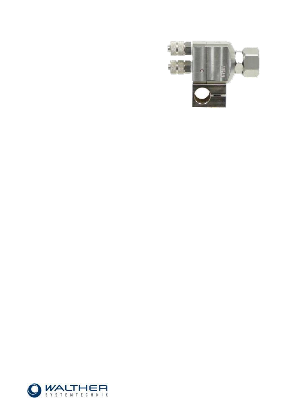
The type label was etched into the casing near the material
connection. The serial number is also hammered into this label.
4.3 Type Label
5 Installation and Start-up
The valve can be installed in any position. A special bracket is also available for a fixed installation (option;
see drawing). The distance to the application area depends upon the desired application width.
During intermittent operations, the device will produce own vibrations. Therefore make sure that the device is
firmly installed. Make sure you avoid extremely high vibrations (can be transferred from device to valve).
5.1 Hose Mounting
Three functional hoses will be mounted as follows:
• Control air (black)
Connection (13): to 3/2-way magnetic valve
• Control air (black)
Connection (13): to 3/2-way magnetic valve
• Sprayed medium (transparent or white)
Connection (14): to pump
Page 8
Rev. 1.1
Assembly Instructions - Spray Valve SMS-13
Page 8 of 26
Walther Systemtechnik GmbH – D 76726 Germersheim
Telefon: +49 (0)7274-7022-0 Telefax: +49 (0)7274-7022-91
http://www.walther-2000.de – info@walther-2000.de
CAUTION
Never point the jet at people. The wearing of eye protection is strongly recommended.
The spraying process can create noise depending on the air and fluid pressures used.
Ear protection should be worn, if required.
WARNING
Danger caused by flammable, harmful fluid. Always follow the safety instructions on the
container or the safety data sheet for the fluid.
IMPORTANT
In case high material pressures are required, make sure that the accident prevention
regulations of the trade associations will be strictly followed!
Important
The maximum material pressure will be 150 bar. It must in no case be exceeded.
Please contact the manufacturer, if you have to work with higher pressures.
6 Operation
6.1 General Information
This device may only be operated if the safety-related equipment is permanently effective and not suspended during operation or altered in its intended effectiveness.
6.2 Operation Instructions / Operating Conditions
As a norm the Airless-Spray Valve SMS-13 operates with a control air pressure of 6 bar.
The application can be controlled as intermitting or continuous. Depending on the individual use, the control
pressure has to be adjusted to the set switching frequency on the one hand and to the higher or lower
material pressures on the other.
For longer standstills, the material can remain in the valve, if it remains under pressure (no contact to outside
air).
Page 9

Rev. 1.1
Assembly Instructions - Spray Valve SMS-13
Page 9 of 26
Walther Systemtechnik GmbH – D 76726 Germersheim
Telefon: +49 (0)7274-7022-0 Telefax: +49 (0)7274-7022-91
http://www.walther-2000.de – info@walther-2000.de
NOTE
Please follow the operating instructions!
NOTE
Please follow the maintenance instructions!
NOTE
Please follow the maintenance instructions!
7 Taking out of Service
7.1 Short Interruption
A short interruption (15 min and more) will always be followed by a clean-spraying.
7.2 Long-term Interruption
The following steps will be observed for a long-term interruption of the device/machine:
Depressurize material supply lines
Remove retainer ring (1) and clean airless-nozzle with a special thinner and a soft cloth. Make sure
that no cloth fibers are left on the nozzle tip.
7.3 Shutdown of Device
The following is important for a shutdown of the machine / device:
Clean airless spray valve with a special thinner.
Page 10

Rev. 1.1
Assembly Instructions - Spray Valve SMS-13
Page 10 of 26
Walther Systemtechnik GmbH – D 76726 Germersheim
Telefon: +49 (0)7274-7022-0 Telefax: +49 (0)7274-7022-91
http://www.walther-2000.de – info@walther-2000.de
CAUTION
Before starting any maintenance or repair work, ensure that all air-operated tools are
depressurized and disconnected from the air supply.
Before opening the spray valve it must be disconnected from the air and fluid supply.
Otherwise, ejected components can cause injuries.
IMPORTANT
Only use soft brushes for outside cleaning of the nozzle tips. Never use metal tools
with sharp edges!
Always maintain utmost cleanliness during repair or replacement work; this applies to
the device as well as to the work area.
We recommend to disassemble the device from the machine or system for all major
repair or maintenance work (make sure that all supply lines are without pressure).
Caution
Depressurize all connections!
8 Maintenance and Repair
8.1 General Information
The airless spray valves of the SMS-13 series are high-quality precision devices which will not fail if treated
correctly and will operate almost maintenance-free. All mobile parts should be regularly oiled and also the
threads should be greased when the nozzles are cleaned or exchanged. Always keep clean and observe
minimum instructions to maintain a long life of the valve. Always use clean and filtered material only. The
control air must also be clean and slightly oiled, if necessary. Maintenance also depends on the individual
operating conditions and the type of media used.
8.2 Cleaning
Wash equipment thoroughly after use to remove residues and dirt, especially if the nozzle needle (7), sealing
or airless nozzles have to be exchanged.
8.3 Installation and Replacement of a Nozzle Needle
Make sure all connections are without pressure. Unscrew the fastening screws (12) of the locking plate (11)
and remove the plate. Remove spring (8) and needle (7). Unscrew retainer ring (1) and pull out airless nozzle (not included in scope of delivery) and the sealing ring (2). Unscrew the nozzle holder (3). Reassemble in
reverse order.
When installing nozzles and nozzle needles which have already been in use, rinse the nozzle with a suitable
thinner to make sure that no residues of material remain. Also the needles shaft will be thoroughly cleaned
from residual particles. Needle shafts with cured material can cause damages at the sealing element (4 + 7).
8.4 Installation and Replacement of an Airless-Nozzle
Make sure all connections are without pressure. Unscrew retainer nut (1). Place airless nozzle on nozzle
holder (3). Make sure that the sealing (2) has been inserted before. Screw fast retainer nut (1).
Page 11

Rev. 1.1
Assembly Instructions - Spray Valve SMS-13
Page 11 of 26
Walther Systemtechnik GmbH – D 76726 Germersheim
Telefon: +49 (0)7274-7022-0 Telefax: +49 (0)7274-7022-91
http://www.walther-2000.de – info@walther-2000.de
IMPORTANT
Sealing and gaskets can be easily damaged. Therefore do not use any sharp-edged or
metal tools for removing and inserting the gaskets!
IMPORTANT
Only use original spare parts from the manufacturer!
Wrong or defective spare parts from other manufacturers can damage the device. If
other than original spare parts of the manufacturer will be used, all obligations from the
manufacturer or his sales partners, such as guarantees, service contracts etc will be
forfeited without further notice.
Walther Systemtechnik GmbH
Hockenheimer Straße 3
D-76726 Germersheim
Germany
Phone ++49(0)7274-7022-0
Telefax ++49(0)7274-7022-91
Email info@walther-2000.de
Internet www.walther-2000.de
IMPORTANT
First check all supply lines for connection and serviceability.
Failure
Possible cause
Action
Nozzle needle does
not open
Not enough control pressure available
Check is sufficient control air pressure is
available (6 bar).
Leakages
Check if O-Ring (7.1) is defective.
Nozzle needle is clogged within needle
sealing (4/6).
Disassemble and clean.
8.5 Inserting new Sealing Elements
From the back of the valve to the bottom of the valve body, the needle sealing (6) will be inserted after the
needle (7) has been pulled out. The O-ring (7.1) can be easily replaced on the disassembled piston. The
sealing (4) will be inserted in the main body; make sure the larger opening shows towards the nozzle. Screw
fast the nozzle holder in order to fix the sealing (4) in its position.
8.6 Spare Parts
8.7 Customer Service / Support
9 Troubleshooting
9.1 General Information
In case of serious problems that cannot be resolved, please contact the Walther Systemtechnik GmbH
customer service.
9.2 Malfunctions:
Page 12

Rev. 1.1
Assembly Instructions - Spray Valve SMS-13
Page 12 of 26
Walther Systemtechnik GmbH – D 76726 Germersheim
Telefon: +49 (0)7274-7022-0 Telefax: +49 (0)7274-7022-91
http://www.walther-2000.de – info@walther-2000.de
10 Appendix
10.1 Dimensioned Drawing for SMS-13
Page 13

Rev. 1.1
Assembly Instructions - Spray Valve SMS-13
Page 13 of 26
Walther Systemtechnik GmbH – D 76726 Germersheim
Telefon: +49 (0)7274-7022-0 Telefax: +49 (0)7274-7022-91
http://www.walther-2000.de – info@walther-2000.de
10.1.1 Spare Part Drawing for SMS-13
Page 14

Rev. 1.1
Assembly Instructions - Spray Valve SMS-13
Page 14 of 26
Walther Systemtechnik GmbH – D 76726 Germersheim
Telefon: +49 (0)7274-7022-0 Telefax: +49 (0)7274-7022-91
http://www.walther-2000.de – info@walther-2000.de
10.1.2 Spare Part List for SMS-13
Draw-No.
Article No.
Qty
Description
1
97410130
1
Retainer nut
2
97640097
1
Sealing ring PA
3
97220583
1
Airless nozzle holder Ø 0.5
alternatives:
3.1
97220633
1
Airless nozzle holder Ø 1.5
3.2
97220693
1
Airless nozzle holder Ø 1.8
4
97640155
1
Variseal 5 97511213
1
Main body SMS-13
6
97640000
1
O-Ring / Viton®
7
97111455
1
Nozzle needle, complete
7.1
97640366
1
O-Ring / Viton®
8
97820088
1
Pressure spring
9
97640052
1
O-Ring / Viton®
10
97640000
3
O-Ring / Viton®
11
97511214
1
Locking plate
12
97610008
3
Cylinder screw DIN 6912
13
97220089
2
Screw joint complete
14
97640162
1
Copper sealing ring
15
97220584
1
High pressure connection
97910015
1
Clamp mounting, complete (OPTIONAL)
IMPORTANT
Always indicate the inscribed serial numbers when ordering spare parts!
Wear parts kit complete for SMS-13 (Standard)
Consisting of:
# Pos. 6 or Pos. 10 (O-ring), 4 each
# Pos. 9 (O-ring), 1 each
# Pos. 7.1 (O-ring), 1 each
# Pos. 4 (Variseal), 1 each
Article-No.
Description
97640542
Wear part kit for SMS-13, VITON
10.2 Wear Parts Kits
Page 15

Rev. 1.1
Assembly Instructions - Spray Valve SMS-13
Page 15 of 26
Walther Systemtechnik GmbH – D 76726 Germersheim
Telefon: +49 (0)7274-7022-0 Telefax: +49 (0)7274-7022-91
http://www.walther-2000.de – info@walther-2000.de
10.3 Airless-Nozzles
Spraying angle
Outlet opening
Spray width in mm
Standard nozzle
Degree
mm
inch
mm
Article No.
5
0,13
0,005
25
bis
50
9705 - 013
10
0,13
0,005
50
bis
75
9710 - 013
15
0,13
0,005
75
bis
100
9715 - 013
20
0,13
0,005
100
bis
125
9720 - 013
25
0,13
0,005
125
bis
150
9725 - 013
5
0,18
0,007
25
bis
50
9705 - 018
10
0,18
0,007
50
bis
75
9710 - 018
15
0,18
0,007
75
bis
100
9715 - 018
20
0,18
0,007
100
bis
125
9720 - 018
25
0,18
0,007
125
bis
150
9725 - 018
30
0,18
0,007
150
bis
175
9730 - 018
33
0,18
0,007
175
bis
200
9733 - 018
40
0,18
0,007
200
bis
225
9740 - 018
50
0,18
0,007
225
bis
250
9750 - 018
65
0,18
0,007
250
bis
275
9765 - 018
5
0,23
0,009
25
bis
50
9705 - 023
10
0,23
0,009
50
bis
75
9710 - 023
15
0,23
0,009
75
bis
100
9715 - 023
20
0,23
0,009
100
bis
125
9720 - 023
25
0,23
0,009
125
bis
150
9725 - 023
30
0,23
0,009
150
bis
175
9730 - 023
33
0,23
0,009
175
bis
200
9733 - 023
40
0,23
0,009
200
bis
225
9740 - 023
50
0,23
0,009
225
bis
250
9750 - 023
65
0,23
0,009
250
bis
275
9765 - 023
5
0,28
0,011
25
bis
50
9705 - 028
10
0,28
0,011
50
bis
100
9710 - 028
20
0,28
0,011
100
bis
150
9720 - 028
33
0,28
0,011
150
bis
200
9733 - 028
40
0,28
0,011
200
bis
250
9740 - 028
50
0,28
0,011
250
bis
300
9750 - 028
65
0,28
0,011
300
bis
350
9765 - 028
73
0,28
0,011
350
bis
400
9773 - 028
5
0,33
0,013
25
bis
50
9705 - 033
10
0,33
0,013
50
bis
100
9710 - 033
20
0,33
0,013
100
bis
150
9720 - 033
33
0,33
0,013
150
bis
200
9733 - 033
40
0,33
0,013
200
bis
250
9740 - 033
50
0,33
0,013
250
bis
300
9750 - 033
Page 16

Rev. 1.1
Assembly Instructions - Spray Valve SMS-13
Page 16 of 26
Walther Systemtechnik GmbH – D 76726 Germersheim
Telefon: +49 (0)7274-7022-0 Telefax: +49 (0)7274-7022-91
http://www.walther-2000.de – info@walther-2000.de
65
0,33
0,013
300
bis
350
9765 - 033
73
0,33
0,013
350
bis
400
9773 - 033
80
0,33
0,013
400
bis
450
9780 - 033
90
0,33
0,013
450
bis
500
9790 - 033
10
0,38
0,015
50
bis
100
9710 - 038
20
0,38
0,015
100
bis
150
9720 - 038
33
0,38
0,015
150
bis
200
9733 - 038
40
0,38
0,015
200
bis
250
9740 - 038
50
0,38
0,015
250
bis
300
9750 - 038
65
0,38
0,015
300
bis
350
9765 - 038
73
0,38
0,015
350
bis
400
9773 - 038
80
0,38
0,015
400
bis
450
9780 - 038
90
0,38
0,015
450
bis
500
9790 - 038
100
0,38
0,015
500
bis
550
97100 - 038
10
0,43
0,017
50
bis
100
9710 - 043
20
0,43
0,017
100
bis
150
9720 - 043
33
0,43
0,017
150
bis
200
9733 - 043
40
0,43
0,017
200
bis
250
9740 - 043
50
0,43
0,017
250
bis
300
9750 - 043
65
0,43
0,017
300
bis
350
9765 - 043
73
0,43
0,017
350
bis
400
9773 - 043
80
0,43
0,017
400
bis
450
9780 - 043
90
0,43
0,017
450
bis
500
9790 - 043
100
0,43
0,017
500
bis
550
97100 - 043
110
0,43
0,017
550
bis
600
97110 - 043
120
0,43
0,017
600
bis
650
97120 - 043
10
0,45
0,018
50
bis
100
9710 - 045
20
0,45
0,018
100
bis
150
9720 - 045
33
0,45
0,018
150
bis
200
9733 - 045
40
0,45
0,018
200
bis
250
9740 - 045
50
0,45
0,018
250
bis
300
9750 - 045
65
0,45
0,018
300
bis
350
9765 - 045
73
0,45
0,018
350
bis
400
9773 - 045
80
0,45
0,018
400
bis
450
9780 - 045
90
0,45
0,018
450
bis
500
9790 - 045
100
0,45
0,018
500
bis
550
97100 - 045
110
0,45
0,018
550
bis
600
97110 - 045
120
0,45
0,018
600
bis
650
97120 - 045
10
0,48
0,019
50
bis
100
9710 - 048
20
0,48
0,019
100
bis
150
9720 - 048
33
0,48
0,019
150
bis
200
9733 - 048
40
0,48
0,019
200
bis
250
9740 - 048
50
0,48
0,019
250
bis
300
9750 - 048
65
0,48
0,019
300
bis
350
9765 - 048
Page 17

Rev. 1.1
Assembly Instructions - Spray Valve SMS-13
Page 17 of 26
Walther Systemtechnik GmbH – D 76726 Germersheim
Telefon: +49 (0)7274-7022-0 Telefax: +49 (0)7274-7022-91
http://www.walther-2000.de – info@walther-2000.de
73
0,48
0,019
350
bis
400
9773 - 048
80
0,48
0,019
400
bis
450
9780 - 048
90
0,48
0,019
450
bis
500
9790 - 048
100
0,48
0,019
500
bis
550
97100 - 048
110
0,48
0,019
550
bis
600
97110 - 048
120
0,48
0,019
600
bis
650
97120 - 048
10
0,53
0,021
50
bis
100
9710 - 053
20
0,53
0,021
100
bis
150
9720 - 053
33
0,53
0,021
150
bis
200
9733 - 053
40
0,53
0,021
200
bis
250
9740 - 053
50
0,53
0,021
250
bis
300
9750 - 053
65
0,53
0,021
300
bis
350
9765 - 053
73
0,53
0,021
350
bis
400
9773 - 053
80
0,53
0,021
400
bis
450
9780 - 053
90
0,53
0,021
450
bis
500
9790 - 053
100
0,53
0,021
500
bis
550
97100 - 053
110
0,53
0,021
550
bis
600
97110 - 053
120
0,53
0,021
600
bis
650
97120 - 053
10
0,58
0,023
50
bis
100
9710 - 058
20
0,58
0,023
100
bis
150
9720 - 058
33
0,58
0,023
150
bis
200
9733 - 058
40
0,58
0,023
200
bis
250
9740 - 058
50
0,58
0,023
250
bis
300
9750 - 058
65
0,58
0,023
300
bis
350
9765 - 058
73
0,58
0,023
350
bis
400
9773 - 058
80
0,58
0,023
400
bis
450
9780 - 058
90
0,58
0,023
450
bis
500
9790 - 058
100
0,58
0,023
500
bis
550
97100 - 058
110
0,58
0,023
550
bis
600
97110 - 058
120
0,58
0,023
600
bis
650
97120 - 058
10
0,63
0,025
50
bis
100
9710 - 063
20
0,63
0,025
100
bis
150
9720 - 063
33
0,63
0,025
150
bis
200
9733 - 063
40
0,63
0,025
200
bis
250
9740 - 063
50
0,63
0,025
250
bis
300
9750 - 063
65
0,63
0,025
300
bis
350
9765 - 063
73
0,63
0,025
350
bis
400
9773 - 063
80
0,63
0,025
400
bis
450
9780 - 063
90
0,63
0,025
450
bis
500
9790 - 063
100
0,63
0,025
500
bis
550
97100 - 063
110
0,63
0,025
550
bis
600
97110 - 063
120
0,63
0,025
600
bis
650
97120 - 063
10
0,66
0,026
50
bis
100
9710 - 066
20
0,66
0,026
100
bis
150
9720 - 066
Page 18

Rev. 1.1
Assembly Instructions - Spray Valve SMS-13
Page 18 of 26
Walther Systemtechnik GmbH – D 76726 Germersheim
Telefon: +49 (0)7274-7022-0 Telefax: +49 (0)7274-7022-91
http://www.walther-2000.de – info@walther-2000.de
33
0,66
0,026
150
bis
200
9733 - 066
40
0,66
0,026
200
bis
250
9740 - 066
50
0,66
0,026
250
bis
300
9750 - 066
65
0,66
0,026
300
bis
350
9765 - 066
73
0,66
0,026
350
bis
400
9773 - 066
80
0,66
0,026
400
bis
450
9780 - 066
90
0,66
0,026
450
bis
500
9790 - 066
100
0,66
0,026
500
bis
550
97100 - 066
110
0,66
0,026
550
bis
600
97110 - 066
120
0,66
0,026
600
bis
650
97120 - 066
10
0,68
0,027
50
bis
100
9710 - 068
20
0,68
0,027
100
bis
150
9720 - 068
33
0,68
0,027
150
bis
200
9733 - 068
40
0,68
0,027
200
bis
250
9740 - 068
50
0,68
0,027
250
bis
300
9750 - 068
65
0,68
0,027
300
bis
350
9765 - 068
73
0,68
0,027
350
bis
400
9773 - 068
80
0,68
0,027
400
bis
450
9780 - 068
90
0,68
0,027
450
bis
500
9790 - 068
100
0,68
0,027
500
bis
550
97100 - 068
110
0,68
0,027
550
bis
600
97110 - 068
120
0,68
0,027
600
bis
650
97120 - 068
10
0,73
0,029
50
bis
100
9710 - 073
20
0,73
0,029
100
bis
150
9720 - 073
33
0,73
0,029
150
bis
200
9733 - 073
40
0,73
0,029
200
bis
250
9740 - 073
50
0,73
0,029
250
bis
300
9750 - 073
65
0,73
0,029
300
bis
350
9765 - 073
73
0,73
0,029
350
bis
400
9773 - 073
80
0,73
0,029
400
bis
450
9780 - 073
90
0,73
0,029
450
bis
500
9790 - 073
100
0,73
0,029
500
bis
550
97100 - 073
110
0,73
0,029
600
bis
650
97110 - 073
120
0,73
0,029
700
bis
750
97120 - 073
10
0,78
0,031
50
bis
100
9710 - 078
20
0,78
0,031
100
bis
150
9720 - 078
33
0,78
0,031
150
bis
200
9733 - 078
40
0,78
0,031
200
bis
250
9740 - 078
50
0,78
0,031
250
bis
300
9750 - 078
65
0,78
0,031
300
bis
350
9765 - 078
73
0,78
0,031
350
bis
400
9773 - 078
80
0,78
0,031
400
bis
450
9780 - 078
90
0,78
0,031
450
bis
500
9790 - 078
100
0,78
0,031
500
bis
550
97100 - 078
110
0,78
0,031
600
bis
650
97110 - 078
Page 19

Rev. 1.1
Assembly Instructions - Spray Valve SMS-13
Page 19 of 26
Walther Systemtechnik GmbH – D 76726 Germersheim
Telefon: +49 (0)7274-7022-0 Telefax: +49 (0)7274-7022-91
http://www.walther-2000.de – info@walther-2000.de
120
0,78
0,031
700
bis
750
97120 - 078
10
0,84
0,033
50
bis
100
9710 - 084
20
0,84
0,033
100
bis
150
9720 - 084
33
0,84
0,033
150
bis
200
9733 - 084
40
0,84
0,033
200
bis
250
9740 - 084
50
0,84
0,033
250
bis
300
9750 - 084
65
0,84
0,033
300
bis
350
9765 - 084
73
0,84
0,033
350
bis
400
9773 - 084
80
0,84
0,033
400
bis
450
9780 - 084
90
0,84
0,033
450
bis
500
9790 - 084
100
0,84
0,033
500
bis
550
97100 - 084
110
0,84
0,033
600
bis
650
97110 - 084
120
0,84
0,033
700
bis
750
97120 - 084
10
0,89
0,035
50
bis
100
9710 - 089
20
0,89
0,035
100
bis
150
9720 - 089
33
0,89
0,035
150
bis
200
9733 - 089
40
0,89
0,035
200
bis
250
9740 - 089
50
0,89
0,035
250
bis
300
9750 - 089
65
0,89
0,035
300
bis
350
9765 - 089
73
0,89
0,035
350
bis
400
9773 - 089
80
0,89
0,035
400
bis
450
9780 - 089
90
0,89
0,035
450
bis
500
9790 - 089
100
0,89
0,035
500
bis
550
97100 - 089
110
0,89
0,035
600
bis
650
97110 - 089
120
0,89
0,035
700
bis
750
97120 - 089
10
0,94
0,037
50
bis
100
9710 - 094
20
0,94
0,037
100
bis
150
9720 - 094
33
0,94
0,037
150
bis
200
9733 - 094
40
0,94
0,037
200
bis
250
9740 - 094
50
0,94
0,037
250
bis
300
9750 - 094
65
0,94
0,037
300
bis
350
9765 - 094
73
0,94
0,037
350
bis
400
9773 - 094
80
0,94
0,037
400
bis
450
9780 - 094
90
0,94
0,037
450
bis
500
9790 - 094
100
0,94
0,037
500
bis
550
97100 - 094
110
0,94
0,037
600
bis
650
97110 - 094
120
0,94
0,037
700
bis
750
97120 - 094
10
0,99
0,039
50
bis
100
9710 - 099
20
0,99
0,039
100
bis
150
9720 - 099
33
0,99
0,039
150
bis
200
9733 - 099
40
0,99
0,039
200
bis
250
9740 - 099
50
0,99
0,039
250
bis
300
9750 - 099
65
0,99
0,039
300
bis
350
9765 - 099
73
0,99
0,039
350
bis
400
9773 - 099
Page 20

Rev. 1.1
Assembly Instructions - Spray Valve SMS-13
Page 20 of 26
Walther Systemtechnik GmbH – D 76726 Germersheim
Telefon: +49 (0)7274-7022-0 Telefax: +49 (0)7274-7022-91
http://www.walther-2000.de – info@walther-2000.de
80
0,99
0,039
400
bis
450
9780 - 099
90
0,99
0,039
450
bis
500
9790 - 099
100
0,99
0,039
500
bis
550
97100 - 099
110
0,99
0,039
600
bis
650
97110 - 099
120
0,99
0,039
700
bis
750
97120 - 099
20
1,04
0,041
100
bis
150
9720 - 104
33
1,04
0,041
150
bis
200
9733 - 104
40
1,04
0,041
200
bis
250
9740 - 104
50
1,04
0,041
250
bis
300
9750 - 104
65
1,04
0,041
300
bis
350
9765 - 104
73
1,04
0,041
350
bis
400
9773 - 104
80
1,04
0,041
400
bis
450
9780 - 104
90
1,04
0,041
450
bis
500
9790 - 104
100
1,04
0,041
500
bis
550
97100 - 104
110
1,04
0,041
600
bis
650
97110 - 104
120
1,04
0,041
700
bis
750
97120 - 104
20
1,09
0,043
100
bis
150
9720 - 109
33
1,09
0,043
150
bis
200
9733 - 109
40
1,09
0,043
200
bis
250
9740 - 109
50
1,09
0,043
250
bis
300
9750 - 109
65
1,09
0,043
300
bis
350
9765 - 109
73
1,09
0,043
350
bis
400
9773 - 109
80
1,09
0,043
400
bis
450
9780 - 109
90
1,09
0,043
450
bis
500
9790 - 109
100
1,09
0,043
500
bis
550
97100 - 109
110
1,09
0,043
600
bis
650
97110 - 109
120
1,09
0,043
700
bis
750
97120 - 109
20
1,14
0,045
100
bis
150
9720 - 114
33
1,14
0,045
150
bis
200
9733 - 114
40
1,14
0,045
200
bis
250
9740 - 114
50
1,14
0,045
250
bis
300
9750 - 114
65
1,14
0,045
300
bis
350
9765 - 114
73
1,14
0,045
350
bis
400
9773 - 114
80
1,14
0,045
400
bis
450
9780 - 114
90
1,14
0,045
450
bis
500
9790 - 114
100
1,14
0,045
500
bis
550
97100 - 114
110
1,14
0,045
600
bis
650
97110 - 114
120
1,14
0,045
700
bis
750
97120 - 114
20
1,19
0,047
100
bis
150
9720 - 119
33
1,19
0,047
150
bis
200
9733 - 119
40
1,19
0,047
200
bis
250
9740 - 119
50
1,19
0,047
250
bis
300
9750 - 119
65
1,19
0,047
300
bis
350
9765 - 119
73
1,19
0,047
350
bis
400
9773 - 119
Page 21

Rev. 1.1
Assembly Instructions - Spray Valve SMS-13
Page 21 of 26
Walther Systemtechnik GmbH – D 76726 Germersheim
Telefon: +49 (0)7274-7022-0 Telefax: +49 (0)7274-7022-91
http://www.walther-2000.de – info@walther-2000.de
80
1,19
0,047
400
bis
450
9780 - 119
90
1,19
0,047
450
bis
500
9790 - 119
100
1,19
0,047
500
bis
550
97100 - 119
110
1,19
0,047
600
bis
650
97110-119
120
1,19
0,047
700
bis
750
97120 - 119
20
1,24
0,049
100
bis
150
9720 - 124
33
1,24
0,049
150
bis
200
9733 - 124
40
1,24
0,049
200
bis
250
9740 - 124
50
1,24
0,049
250
bis
300
9750 - 124
65
1,24
0,049
300
bis
350
9765 - 124
73
1,24
0,049
350
bis
400
9773 - 124
80
1,24
0,049
400
bis
450
9780 - 124
90
1,24
0,049
450
bis
500
9790 - 124
100
1,24
0,049
500
bis
550
97100 - 124
110
1,24
0,049
600
bis
650
97110 - 124
120
1,24
0,049
700
bis
750
97120 - 124
20
1,29
0,051
100
bis
150
9720 - 129
33
1,29
0,051
150
bis
200
9733 - 129
40
1,29
0,051
200
bis
250
9740 - 129
50
1,29
0,051
250
bis
300
9750 - 129
65
1,29
0,051
300
bis
350
9765 - 129
73
1,29
0,051
350
bis
400
9773 - 129
80
1,29
0,051
400
bis
450
9780 - 129
90
1,29
0,051
450
bis
500
9790 - 129
100
1,29
0,051
500
bis
550
97100 - 129
110
1,29
0,051
600
bis
650
97110 - 129
120
1,29
0,051
700
bis
750
97120 - 129
20
1,32
0,053
100
bis
150
9720 - 132
33
1,32
0,053
150
bis
200
9733 - 132
40
1,32
0,053
200
bis
250
9740 - 132
50
1,32
0,053
250
bis
300
9750 - 132
65
1,32
0,053
300
bis
350
9765 - 132
73
1,32
0,053
350
bis
400
9773 - 132
80
1,32
0,053
400
bis
450
9780 - 132
90
1,32
0,053
450
bis
500
9790 - 132
100
1,32
0,053
500
bis
550
97100 - 132
110
1,32
0,053
600
bis
650
97110 - 132
120
1,32
0,053
700
bis
750
97120 - 132
20
1,35
0,053
100
bis
150
9720 - 135
33
1,35
0,053
150
bis
200
9733 - 135
40
1,35
0,053
200
bis
250
9740 - 135
50
1,35
0,053
250
bis
300
9750 - 135
65
1,35
0,053
300
bis
350
9765 - 135
73
1,35
0,053
350
bis
400
9773 - 135
Page 22

Rev. 1.1
Assembly Instructions - Spray Valve SMS-13
Page 22 of 26
Walther Systemtechnik GmbH – D 76726 Germersheim
Telefon: +49 (0)7274-7022-0 Telefax: +49 (0)7274-7022-91
http://www.walther-2000.de – info@walther-2000.de
80
1,35
0,053
400
bis
450
9780 - 135
90
1,35
0,053
450
bis
500
9790 - 135
100
1,35
0,053
500
bis
550
97100 - 135
110
1,35
0,053
600
bis
650
97110 - 135
120
1,35
0,053
700
bis
750
97120 - 135
20
1,40
0,055
100
bis
150
9720 - 140
33
1,40
0,055
150
bis
200
9733 - 140
40
1,40
0,055
200
bis
250
9740 - 140
50
1,40
0,055
250
bis
300
9750 - 140
65
1,40
0,055
300
bis
350
9765 - 140
73
1,40
0,055
350
bis
400
9773 - 140
80
1,40
0,055
400
bis
450
9780 - 140
90
1,40
0,055
450
bis
500
9790 - 140
100
1,40
0,055
500
bis
550
97100 - 140
110
1,40
0,055
600
bis
650
97110 - 140
120
1,40
0,055
700
bis
750
97120 - 140
20
1,45
0,057
100
bis
150
9720 - 145
33
1,45
0,057
150
bis
200
9733 - 145
40
1,45
0,057
200
bis
250
9740 - 145
50
1,45
0,057
250
bis
300
9750 - 145
65
1,45
0,057
300
bis
350
9765 - 145
73
1,45
0,057
350
bis
400
9773 - 145
80
1,45
0,057
400
bis
450
9780 - 145
90
1,45
0,057
450
bis
500
9790 - 145
100
1,45
0,057
500
bis
550
97100 - 145
110
1,45
0,057
600
bis
650
97110 - 145
120
1,45
0,057
700
bis
750
97120 - 145
20
1,50
0,059
100
bis
150
9720 - 150
33
1,50
0,059
150
bis
200
9733 - 150
40
1,50
0,059
200
bis
250
9740 - 150
50
1,50
0,059
250
bis
300
9750 - 150
65
1,50
0,059
300
bis
350
9765 - 150
73
1,50
0,059
350
bis
400
9773 - 150
80
1,50
0,059
400
bis
450
9780 - 150
90
1,50
0,059
450
bis
500
9790 - 150
100
1,50
0,059
500
bis
550
97100 - 150
110
1,50
0,059
600
bis
650
97110 - 150
120
1,50
0,059
700
bis
750
97120 - 150
20
1,55
0,061
100
bis
150
9720 - 155
33
1,55
0,061
150
bis
200
9733 - 155
40
1,55
0,061
200
bis
250
9740 - 155
50
1,55
0,061
250
bis
300
9750 - 155
65
1,55
0,061
300
bis
350
9765 - 155
73
1,55
0,061
350
bis
400
9773 - 155
Page 23

Rev. 1.1
Assembly Instructions - Spray Valve SMS-13
Page 23 of 26
Walther Systemtechnik GmbH – D 76726 Germersheim
Telefon: +49 (0)7274-7022-0 Telefax: +49 (0)7274-7022-91
http://www.walther-2000.de – info@walther-2000.de
80
1,55
0,061
400
bis
450
9780 - 155
90
1,55
0,061
450
bis
500
9790 - 155
100
1,55
0,061
500
bis
550
97100 - 155
110
1,55
0,061
600
bis
650
97110 - 155
120
1,55
0,061
700
bis
750
97120 - 155
20
1,57
0,062
100
bis
150
9720 - 157
33
1,57
0,062
150
bis
200
9733 - 157
40
1,57
0,062
200
bis
250
9740 - 157
50
1,57
0,062
250
bis
300
9750 - 157
65
1,57
0,062
300
bis
350
9765 - 157
73
1,57
0,062
350
bis
400
9773 - 157
80
1,57
0,062
400
bis
450
9780 - 157
90
1,57
0,062
450
bis
500
9790 - 157
100
1,57
0,062
500
bis
550
97100 - 157
110
1,57
0,062
600
bis
650
97110 - 157
120
1,57
0,062
700
bis
750
97120 - 157
20
1,60
0,063
100
bis
150
9720 - 160
33
1,60
0,063
150
bis
200
9733 - 160
40
1,60
0,063
200
bis
250
9740 - 160
50
1,60
0,063
250
bis
300
9750 - 160
65
1,60
0,063
300
bis
350
9765 - 160
73
1,60
0,063
350
bis
400
9773 - 160
80
1,60
0,063
400
bis
450
9780 - 160
90
1,60
0,063
450
bis
500
9790 - 160
100
1,60
0,063
500
bis
550
97100 - 160
110
1,60
0,063
600
bis
650
97110 - 160
120
1,60
0,063
700
bis
750
97120 - 160
20
1,65
0,065
100
bis
150
9720 - 165
33
1,65
0,065
150
bis
200
9733 - 165
40
1,65
0,065
200
bis
250
9740 - 165
50
1,65
0,065
250
bis
300
9750 - 165
65
1,65
0,065
300
bis
350
9765 - 165
73
1,65
0,065
350
bis
400
9773 - 165
80
1,65
0,065
400
bis
450
9780 - 165
90
1,65
0,065
450
bis
500
9790 - 165
100
1,65
0,065
500
bis
550
97100 - 165
110
1,65
0,065
600
bis
650
97110 - 165
120
1,65
0,065
700
bis
750
97120 - 165
20
1,70
0,067
100
bis
150
9720 - 170
33
1,70
0,067
150
bis
200
9733 - 170
40
1,70
0,067
200
bis
250
9740 - 170
50
1,70
0,067
250
bis
300
9750 - 170
65
1,70
0,067
300
bis
350
9765 - 170
73
1,70
0,067
350
bis
400
9773 - 170
Page 24

Rev. 1.1
Assembly Instructions - Spray Valve SMS-13
Page 24 of 26
Walther Systemtechnik GmbH – D 76726 Germersheim
Telefon: +49 (0)7274-7022-0 Telefax: +49 (0)7274-7022-91
http://www.walther-2000.de – info@walther-2000.de
80
1,70
0,067
400
bis
450
9780 - 170
90
1,70
0,067
450
bis
500
9790 - 170
100
1,70
0,067
500
bis
550
97100 - 170
110
1,70
0,067
600
bis
650
97110 - 170
120
1,70
0,067
700
bis
750
97120 - 170
20
1,75
0,069
100
bis
150
9720 - 175
33
1,75
0,069
150
bis
200
9733 - 175
40
1,75
0,069
200
bis
250
9740 - 175
50
1,75
0,069
250
bis
300
9750 - 175
65
1,75
0,069
300
bis
350
9765 - 175
73
1,75
0,069
350
bis
400
9773 - 175
80
1,75
0,069
400
bis
450
9780 - 175
90
1,75
0,069
450
bis
500
9790 - 175
100
1,75
0,069
500
bis
550
97100 - 175
110
1,75
0,069
600
bis
650
97110 - 175
120
1,75
0,069
700
bis
750
97120 - 175
20
1,80
0,071
100
bis
150
9720 - 180
33
1,80
0,071
150
bis
200
9733 - 180
40
1,80
0,071
200
bis
250
9740 - 180
50
1,80
0,071
250
bis
300
9750 - 180
65
1,80
0,071
300
bis
350
9765 - 180
73
1,80
0,071
350
bis
400
9773 - 180
80
1,80
0,071
400
bis
450
9780 - 180
90
1,80
0,071
450
bis
500
9790 - 180
100
1,80
0,071
500
bis
550
97100 - 180
110
1,80
0,071
600
bis
650
97110 - 180
120
1,80
0,071
700
bis
750
97120 - 180
20
1,83
0,072
100
bis
150
9720 - 183
33
1,83
0,072
150
bis
200
9733 - 183
40
1,83
0,072
200
bis
250
9740 - 183
50
1,83
0,072
250
bis
300
9750 - 183
65
1,83
0,072
300
bis
350
9765 - 183
73
1,83
0,072
350
bis
400
9773 - 183
80
1,83
0,072
400
bis
450
9780 - 183
90
1,83
0,072
450
bis
500
9790 - 183
100
1,83
0,072
500
bis
550
97100 - 183
110
1,83
0,072
600
bis
650
97110 - 183
120
1,83
0,072
700
bis
750
97120 - 183
20
1,85
0,073
100
bis
150
9720 - 185
33
1,85
0,073
150
bis
200
9733 - 185
40
1,85
0,073
200
bis
250
9740 - 185
50
1,85
0,073
250
bis
300
9750 - 185
65
1,85
0,073
300
bis
350
9765 - 185
73
1,85
0,073
350
bis
400
9773 - 185
Page 25

Rev. 1.1
Assembly Instructions - Spray Valve SMS-13
Page 25 of 26
Walther Systemtechnik GmbH – D 76726 Germersheim
Telefon: +49 (0)7274-7022-0 Telefax: +49 (0)7274-7022-91
http://www.walther-2000.de – info@walther-2000.de
80
1,85
0,073
400
bis
450
9780 - 185
90
1,85
0,073
450
bis
500
9790 - 185
100
1,85
0,073
500
bis
550
97100 - 185
110
1,85
0,073
600
bis
650
97110 - 185
120
1,85
0,073
700
bis
750
97120 - 185
20
1,91
0,075
100
bis
150
9720 - 191
33
1,91
0,075
150
bis
200
9733 - 191
40
1,91
0,075
200
bis
250
9740 - 191
50
1,91
0,075
250
bis
300
9750 - 191
65
1,91
0,075
300
bis
350
9765 - 191
73
1,91
0,075
350
bis
400
9773 - 191
80
1,91
0,075
400
bis
450
9780 - 191
90
1,91
0,075
450
bis
500
9790 - 191
100
1,91
0,075
500
bis
550
97100 - 191
110
1,91
0,075
600
bis
650
97110 - 191
120
1,91
0,075
700
bis
750
97120 - 191
Page 26

Rev. 1.1
Assembly Instructions - Spray Valve SMS-13
Page 26 of 26
Walther Systemtechnik GmbH – D 76726 Germersheim
Telefon: +49 (0)7274-7022-0 Telefax: +49 (0)7274-7022-91
http://www.walther-2000.de – info@walther-2000.de
10.4 Accessories
Figure
Article Number
Description
979444
Cleaning set
(see also Product catalog ACCESSORIES)
 Loading...