

Page 1
Rev. 1.3
Assembly Instructions – Spray Valve SMS-05
Page 1 of 31
Walther Systemtechnik GmbH – D 76726 Germersheim
Telefon: +49 (0)7274-7022-0 Telefax: +49 (0)7274-7022-91
http://www.walther-2000.de – info@walther-2000.de
Assembly Instructions
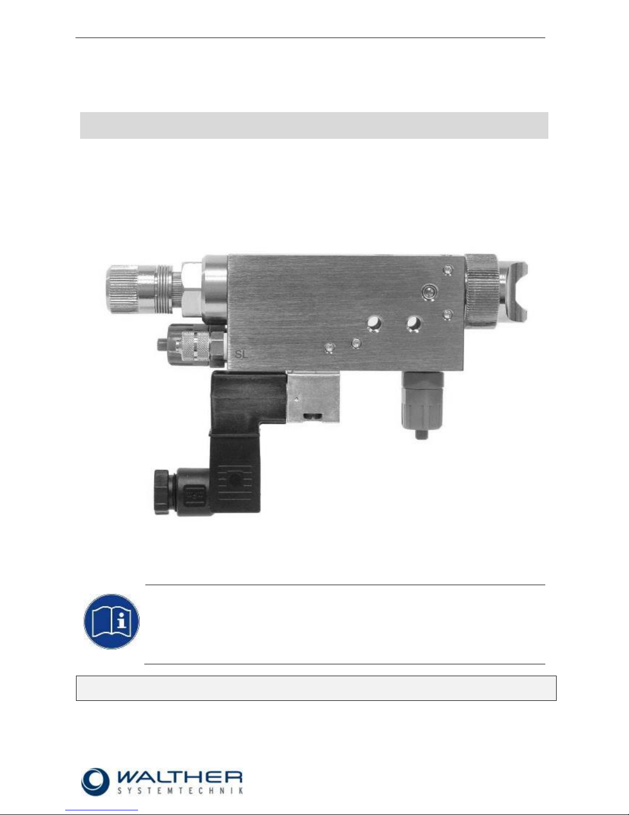
Spray Valve SMS-05
Article Number: S05-….
Figure: Spray Valve SMS-05 with flat-jet air cap and raster needle lock
NOTE
Please read the Assembly Instructions carefully before first using the incomplete device and
strictly adhere to the instructions!
The incomplete device may only be worked with and worked on by persons who are familiar
with the assembly instructions and the current regulations for industrial safety and accident
prevention.
Always keep this translated version of the “Original Assembly Instructions“ at the incomplete
device! The instructions have to be available anytime!
Page 2

Rev. 1.3
Assembly Instructions – Spray Valve SMS-05
Page 2 of 31
Walther Systemtechnik GmbH – D 76726 Germersheim
Telefon: +49 (0)7274-7022-0 Telefax: +49 (0)7274-7022-91
http://www.walther-2000.de – info@walther-2000.de
Table of Contents
Page
EC DECLARATION OF INCORPORATION ....................................................................................................................... 4
1 INTRODUCTION ................................................................................................................................................. 5
1.1 TARGET GROUP OF THE ASSEMBLY INSTRUCTIONS ............................................................................................................ 5
1.2 LIST OF SIGNS AND SYMBOLS ....................................................................................................................................... 5
2 SAFETY............................................................................................................................................................... 5
2.1 GENERAL INFORMATION ............................................................................................................................................. 5
2.2 DANGERS FROM RESIDUAL ENERGY ............................................................................................................................... 5
2.3 WARRANTY AND LIABILITY ........................................................................................................................................... 5
2.4 CORRECT USE ........................................................................................................................................................... 6
2.5 INCORRECT USE ........................................................................................................................................................ 6
2.6 QUALIFICATION OF PERSONNEL .................................................................................................................................... 6
3 TRANSPORT ....................................................................................................................................................... 7
3.1 PACKAGING .............................................................................................................................................................. 7
3.2 TASKS BEFORE TRANSPORT .......................................................................................................................................... 7
4 DESCRIPTION OF FUNCTION .............................................................................................................................. 7
4.1 DESIGNATED PURPOSE ................................................................................................................................................ 7
4.2 TECHNICAL DATA ....................................................................................................................................................... 8
4.3 TYPE LABEL .............................................................................................................................................................. 8
5 MOUNTING AND FIRST START-UP ...................................................................................................................... 8
5.1 HOSE MOUNTING...................................................................................................................................................... 8
5.2 TOTAL VIEW / DESCRIPTION ......................................................................................................................................... 9
5.3 ADJUSTING THE DEVICE .............................................................................................................................................. 9
5.4 SMS-05 WITH RASTER NEEDLE SENSOR ...................................................................................................................... 10
5.4.1 Terminal Assignment for Needle Detection ............................................................................................... 10
5.4.2 Terminal Assignment for Solenoid Valve ................................................................................................... 10
5.5 INSTALLATION DIAGRAM FOR COLOR MARKING SYSTEMS ................................................................................................ 11
6 OPERATION ..................................................................................................................................................... 11
6.1 GENERAL INFORMATION ........................................................................................................................................... 11
6.2 OPERATION INSTRUCTIONS / OPERATING CONDITIONS .................................................................................................... 11
6.3 OPERATING ELEMENTS ............................................................................................................................................. 12
7 MAINTENANCE AND REPAIR ............................................................................................................................ 13
7.1 GENERAL INFORMATION ........................................................................................................................................... 13
7.2 CLEANING .............................................................................................................................................................. 13
7.3 REPLACING THE SEALING SCREW ................................................................................................................................ 13
7.4 REPLACING NOZZLE AND NEEDLE ................................................................................................................................ 14
7.5 REPLACING SEALING ELEMENTS (RASTER NEEDLE SENSOR) .............................................................................................. 14
7.6 MAINTENANCE FOR USE IN COLOR MARKING SYSTEMS (NORMAL OPERATION) ................................................................... 15
7.7 SPARE PARTS .......................................................................................................................................................... 16
7.8 CUSTOMER SERVICE / SUPPORT .................................................................................................................................. 16
8 TROUBLESHOOTING ........................................................................................................................................ 16
8.1 GENERAL INFORMATION ........................................................................................................................................... 16
8.2 MALFUNCTIONS: ..................................................................................................................................................... 16
8.3 SPRAY IMAGE / TYPE OF DEFECT ................................................................................................................................. 17
9 TAKING OUT OF SERVICE ................................................................................................................................. 18
9.1 SHORT INTERRUPTION .............................................................................................................................................. 18
9.2 LONG-TERM INTERRUPTION ....................................................................................................................................... 18
9.3 SHUTDOWN OF DEVICE ............................................................................................................................................. 18
Page 3

Rev. 1.3
Assembly Instructions – Spray Valve SMS-05
Page 3 of 31
Walther Systemtechnik GmbH – D 76726 Germersheim
Telefon: +49 (0)7274-7022-0 Telefax: +49 (0)7274-7022-91
http://www.walther-2000.de – info@walther-2000.de
10 APPENDIX ........................................................................................................................................................ 19
10.1 DIMENSIONED DRAWING SMS-05 ........................................................................................................................ 19
10.1.1 Spare Part Drawing SMS-05 ................................................................................................................. 20
10.1.2 Spare Part Liste SMS-05 ........................................................................................................................ 21
10.2 ARTICLE NUMBERS FOR AIR CAPS .......................................................................................................................... 22
10.3 ARTICLE NUMBERS FOR NOZZLES ........................................................................................................................... 23
10.4 ARTICLE NUMBERS FOR NOZZLE NEEDLES ................................................................................................................ 24
10.5 ARTICLE NUMBERS FOR VALVES ............................................................................................................................. 25
10.6 ARTICLE NUMBERS THREADED JOINTS..................................................................................................................... 25
10.7 WEAR-AND-TEAR PARTS ...................................................................................................................................... 26
10.8 ACCESSORIES ..................................................................................................................................................... 27
10.8.1 Center hole for Centering sleeve 97320602 .......................................................................................... 28
10.8.2 Add-on Elements .................................................................................................................................. 29
10.8.3 Description of Pneumatic Needle-Stroke Adjustment 978000037 ........................................................ 30
Page 4

Rev. 1.3
Assembly Instructions – Spray Valve SMS-05
Page 4 of 31
Walther Systemtechnik GmbH – D 76726 Germersheim
Telefon: +49 (0)7274-7022-0 Telefax: +49 (0)7274-7022-91
http://www.walther-2000.de – info@walther-2000.de
EC Declaration of Incorporation
in accordance with EU Machinery Directive 2006/42/EU, dated 17 May 2006, Appendix II B
We herewith confirm that the below mentioned incomplete device meets the basic requirements for safety
and health as stated in EU Machinery Directive 2006/42/EU for its design and construction as well as for the
configuration released by us on the market. This machine component will not be operated before it has been
determined that the incomplete system where the machine component will be installed also meets the
requirements of the Directive (2006/42/EG).
Manufacturer
Walther Systemtechnik GmbH
Hockenheimer Straße 3
D- 76726 Germersheim
Description
Spray valve SMS-05, Article No. S05-…
We also declare the conformity with other, product-relevant directives/guidelines:
Mach. Direct. 2006/42/EU App. I, Clause: 1.1.2, 1.1.3, 1.1.5, 1.1.6, 1.3.2, 1.3.3,
1.3.4, 1.5.1, 1.5.8, 1.5.9
EMC- Directive 2014/30/EU, dated 26. February 2014
Applied harmonized standards, in particular:
DIN EN ISO 12100 Safety of Machinery – General Design Principles –
Risk Assessment and Risk Reduction (ISO
12100:2010)
In addition, we also confirm that the special documentation according to Appendix VII Part B has
been prepared.
The manufacturer, respectively his authorized representative obligates himself to submit this documentation
to the market surveillance authorities, if requested.
This EC Declaration of Incorporation becomes invalid if the incomplete device will be altered or changed
without consent of Walther Systemtechnik GmbH.
Authorized representative for Technical Documentation:
Stefan Hirl, Hockenheimer Straße 3, D- 76726 Germersheim
Germersheim, 19 April 2018
(Place, Date) (Stefan Hirl, Management)
Page 5
Rev. 1.3
Assembly Instructions – Spray Valve SMS-05
Page 5 of 31
Walther Systemtechnik GmbH – D 76726 Germersheim
Telefon: +49 (0)7274-7022-0 Telefax: +49 (0)7274-7022-91
http://www.walther-2000.de – info@walther-2000.de
1 Introduction
1.1 Target Group of the Assembly Instructions
Operating Personnel
Maintenance Personnel
1.2 List of Signs and Symbols
The assembly instructions warn users of operations which may put their health at risk.
The warnings are indicated by combinations of text and symbols as follows:
DANGER
Describes a potentially dangerous situation.
Death, grievous bodily harm or severe material damage WILL occur if the respective
measures of precaution have not been taken
WARNING
Describes a potentially dangerous situation.
Death, grievous bodily harm or severe material damage MAY occur if the respective
measures of precaution have not been taken.
CAUTION
Describes a potentially dangerous situation.
Slight injuries CAN occur if the respective measures of precaution have not been taken. This
signal word is also used to describe possible property damages.
IMPORTANT
Indicates tips for usage and other particularly useful information.
No dangerous situation.
2 Safety
2.1 General Information
The construction of this device is according to the latest technology and is absolutely reliable. The individual
components as well as the complete device are continuously checked by our quality management.
2.2 Dangers from Residual Energy
Please instruct the operating personnel on the respective measures to be taken against the occurrence of
mechanical, hydraulic, pneumatic and electric / electronic residual energies.
2.3 Warranty and Liability
According to the conditions laid down by the German Engineering Association (VDMA), Walther Systemtechnik GmbH has a guarantee of 12 months under normal European operating conditions on its own
parts (spare parts are excluded); or according to the conditions of the manufacturer.
This guarantee can only be granted by Walther Systemtechnik GmbH, if:
the user has thorough knowledge of the content of the assembly instructions;
the user follows the instructions and notes contained in the assembly instructions;
the user does not rebuild or make changes on parts of the device without prior consent of WST Sys-
temtechnik GmbH.
Page 6
Rev. 1.3
Assembly Instructions – Spray Valve SMS-05
Page 6 of 31
Walther Systemtechnik GmbH – D 76726 Germersheim
Telefon: +49 (0)7274-7022-0 Telefax: +49 (0)7274-7022-91
http://www.walther-2000.de – info@walther-2000.de
2.4 Correct Use
This device is a needle valve and will be used for processing materials which can be sprayed in continuous
or intermitting operation. Under no circumstances shall aggressive media such as acids, alkaline solutions,
detergents, chemicals or others be sprayed. If you are not sure, please contact the manufacturer if a certain
spray medium is suitable for this device.
2.5 Incorrect Use
Operating the incomplete device with insufficient knowledge about the operation, maintenance and care
of the device.
Making changes, extensions or alterations on the incomplete device that may hamper its safety without
the prior consent of Walther Systemtechnik GmbH.
Operating the incomplete device with defective safety installations or not properly attached or malfunc-
tioning safety devices.
Using unsuitable materials.
Handling the incomplete device while energized
2.6 Qualification of Personnel
Only trained and instructed personnel may conduct work on the equipment.
The responsibilities of the personnel for assembly work, operation, repair work or maintenance work must be
clearly assigned to individuals!
Persons in training may work with the equipment only under supervision of an experienced person.
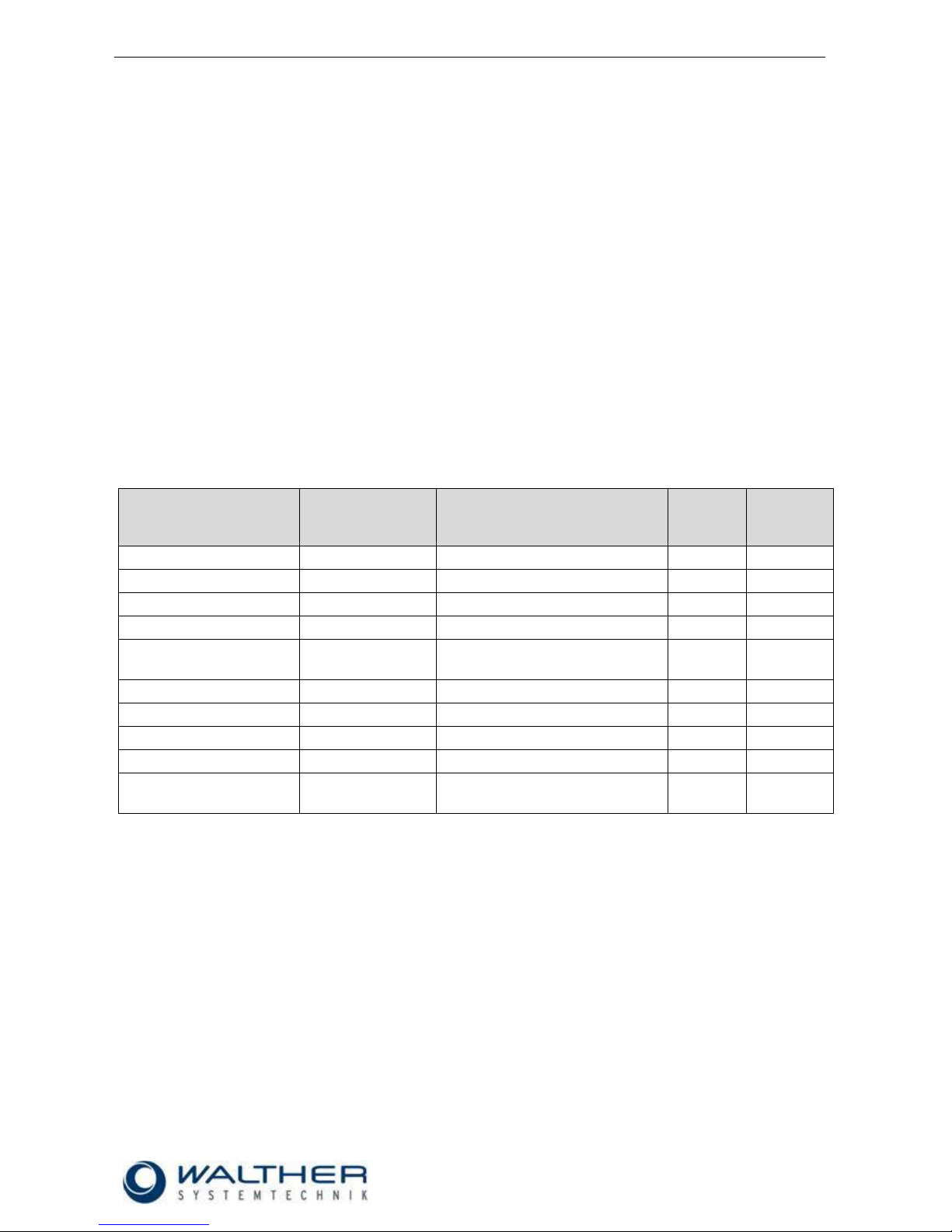
Personnel
Task
Instructed
Personnel
Personnel with Technical
Qualification
Specialist
Supervisor
Packaging, Transport
X
-
-
-
Commissioning
X
X
-
Operation
X
-
Troubleshooting, general
X
X
-
Troubleshooting
mechanical
-
X
-
-
Troubleshooting electrical
-
-
X
-
Setting up
-
X
-
-
Maintenance
-
X
-
-
Repair
-
X
X
-
Taking out of service,
Storage
-
X
X
-
Page 7

Rev. 1.3
Assembly Instructions – Spray Valve SMS-05
Page 7 of 31
Walther Systemtechnik GmbH – D 76726 Germersheim
Telefon: +49 (0)7274-7022-0 Telefax: +49 (0)7274-7022-91
http://www.walther-2000.de – info@walther-2000.de
3 Transport
3.1 Packaging
The type of packaging depends on the individual mode of shipping. If not separately contracted, the
packaging is in accordance with the rules and regulations of Walther Systemtechnik GmbH. This rule is in
accordance with the Federal Association for Packaging HPE.
3.2 Tasks before Transport
The following has to be done before transport:
Disconnect all power lines.
The actual transport of the incomplete device and its individual parts requires special care in order to prevent
damages from external forceful impact or careless on- and off-loading. Depending on the mode of
transportation, suitable transport and load securing has to be selected. The incomplete device will be aligned
and leveled by appropriate fastening elements.
4 Description of Function
4.1 Designated Purpose
The spray valves of SMS-05 series are suitable for the application of liquid up to viscous media, such as
grease, oil, separating agents, colors or glues. One of the major characteristics of the SMS-05 series is the
stepless adjusting of the spraying width as well as the integrated control valve for pre air and purging air.
Depending on the viscosity of the medium to be applied, the application pattern can be individually adjusted
via the nozzle size, the atomizing air pressure and material pressure. The supply line of the atomizing air,
control air and the medium takes place via three hoses. Connections No. 7.0 and No. 8.0 are additional optional material connections for the material circulation (i.e. circulation via nozzle head).
CAUTION
The use of other media can cause functional failures, material damages or even the
complete destruction of the device.
The SMS-05 Spraying Valve is an electro-pneumatically controlled application device. Extremely short
control air paths, facilitated by the directly attached 3/2-way solenoid valve (pos.18.0), bring about a fast and
very exact opening and closing of the needle (pos.13.0). The air valve (pos.12.0) connected with the needle
(pos.13.0) receives air pressure on the surface via the 3/2-way solenoid valve. This opens the air valve
(pos.12.0) such that the atomizing air (“pre air”) is released. Not until the spring (pos.12.4) is completely
compressed, the air valve (pos. 12.0) moves the needle (pos.13.0), and the medium comes out of the
nozzle. If the control air is switched off or fails, this spring (pos. 14.0) will cause the needle to close, whereby
the needle first closes the nozzle and thereafter the air valve (“purging air”) will close. The pre air and the
purging air help to keep the nozzle (pos. 3.0) clean.
The material pressure (1/8"-connection - pos. 5.0) must be adjusted to the desired spray pattern and, thus, to
the atomizing air pressure (1/8"-connection - pos. 17.0).
It can be used for continuous as well as intermittent spraying. The control air impulses (M5-connection - pos.
16.0) are transmitted to the working piston via the 3/2-way solenoid valve (pos. 18.0).
Depending on the particular application case it must be ensured that the control air is adjusted to the number
of operating cycles.
Page 8
Rev. 1.3
Assembly Instructions – Spray Valve SMS-05
Page 8 of 31
Walther Systemtechnik GmbH – D 76726 Germersheim
Telefon: +49 (0)7274-7022-0 Telefax: +49 (0)7274-7022-91
http://www.walther-2000.de – info@walther-2000.de
4.2 Technical Data
General Data
Dimensions [mm]
ca.126 x 22 x 82.5 with air cap – round jet
ca.129 x 22 x 82.5 with air cap – flat je
Weight [g]
ca. 500
Energy Supply
Control air pressure [bar]
4.5 – 6
Atomizer air pressure [bar]
0.5 – 5 (minimum 0.5 bar lower than control pressure)
Material pressure [bar]
max. 15 bar
4.3 Type Label
The type designation is etched in the casing. The serial number is
also inscribed in this area.
5 Mounting and First Start-up
The valves can be installed in any position. The spraying width for middle air (ML) and cone air (HL) can be
individually regulated. The possibility for using either round or flat spray air caps is given.
Vibrations of the valve caused by fast intermitting cycles require solid and tight installation. Excessive
machine vibrations to the valves should be avoided.
5.1 Hose Mounting
The three functional hoses will be connected as follows:
Atomizing air (blue)
Connection ZL (17.0): M5
Control air (black)
Connection SL (16.0): 1/8"
Material (transparent)
Connection M (5.0): 1/8"-to
pressure tank or pump
Material circulation (Optional)
Connection M (5.0): M5 – to
pressure tank or pump
Material circulation (Optional)
Connection M (5.0): M5- to
pressure tank or pump
Page 9
Rev. 1.3
Assembly Instructions – Spray Valve SMS-05
Page 9 of 31
Walther Systemtechnik GmbH – D 76726 Germersheim
Telefon: +49 (0)7274-7022-0 Telefax: +49 (0)7274-7022-91
http://www.walther-2000.de – info@walther-2000.de
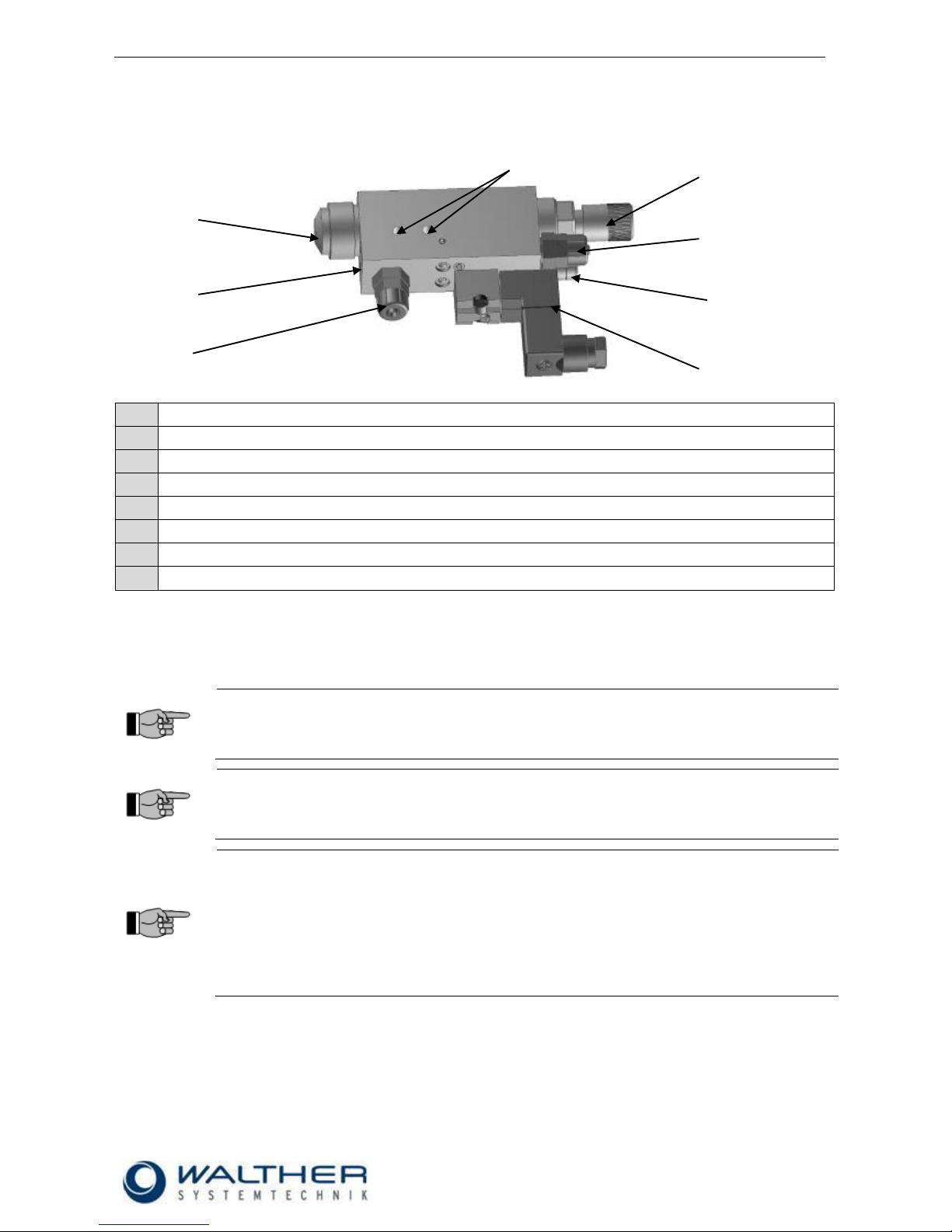
5.2 Total View / Description
1
Basic casing
2
Nozzle with air cap and retainer ring
3
Raster needle lock
4
3/2-way solenoid valve
5
Material connection
6
Atomizer air connection
7
Control air connection
8
2x fastening thread M5
5.3 Adjusting the Device
The amount of material can be regulated via the stroke adjustment of the needle. A left turn of the regulating
knob increases the material amount. A fine precision thread affects a needle rise that results in an adjustment of 0.5 mm with each turn of the adjusting knob.
IMPORTANT
Do not turn the regulating knob further to the left if no more stops are noticeable while turning
it! The maximum fluid outlet has been reached!
A further turning will damage the raster needle screw!
IMPORTANT
Nozzle and needle can be damaged by wrong handling. Only decrease the material flow (by a
right turn of the regulating knob) if material spills out. Do not turn the regulating knob further to
the right after the nozzle is closed!
NOTE
The duration of the post-spray air will be individually adjusted from outside at the spray valve.
Turn the regulating screw (10.4.0) which is inserted in the side (view in spray direction: right)
with a screwdriver in order to control the duration of the post-spray air as follows:
right turn = longer duration of post-spray air
left turn = shorter duration of post-spray air
Basic setting = screw is flush with basic body; then make one full turn to the
right
3 8 6 7 4 2 5
1
Page 10
Rev. 1.3
Assembly Instructions – Spray Valve SMS-05
Page 10 of 31
Walther Systemtechnik GmbH – D 76726 Germersheim
Telefon: +49 (0)7274-7022-0 Telefax: +49 (0)7274-7022-91
http://www.walther-2000.de – info@walther-2000.de
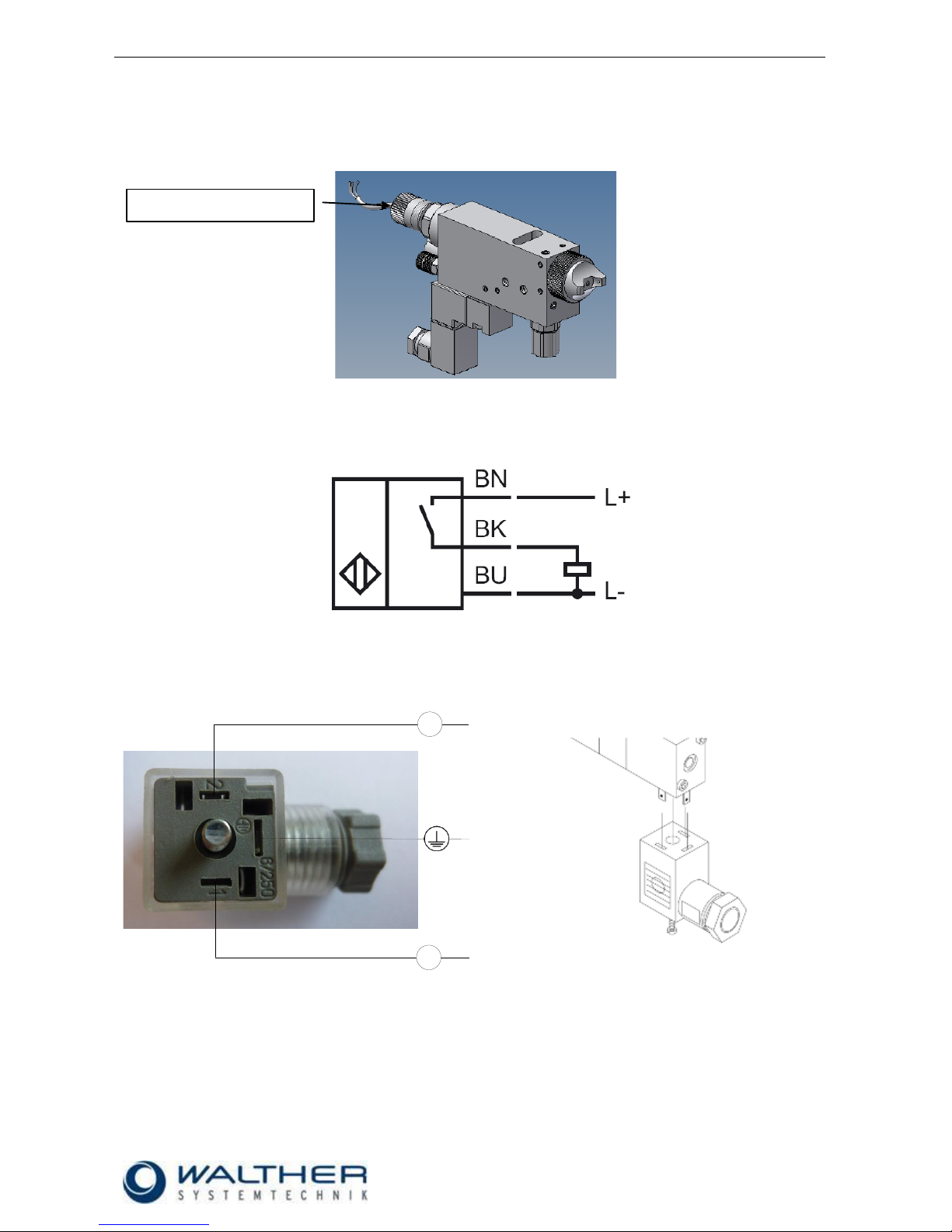
5.4 SMS-05 with Raster Needle Sensor
Optionally, you can use a raster-needle lock with a pre-installed, inductive proximity switch. It will release a
signal when the needle piston with the needle is open. This will help you in digitally monitoring the status
„nozzle open“.
5.4.1 Terminal Assignment for Needle Detection
5.4.2 Terminal Assignment for Solenoid Valve
+
-
Standard plug 24V Valve (left [+] and right [-])
Raster needle sensor
Page 11

Rev. 1.3
Assembly Instructions – Spray Valve SMS-05
Page 11 of 31
Walther Systemtechnik GmbH – D 76726 Germersheim
Telefon: +49 (0)7274-7022-0 Telefax: +49 (0)7274-7022-91
http://www.walther-2000.de – info@walther-2000.de
5.5 Installation Diagram for Color Marking Systems
6 Operation
6.1 General Information
This device may only be operated if the safety-related equipment is permanently effective and not suspended during operation or altered in its intended effectiveness.
6.2 Operation Instructions / Operating Conditions
CAUTION
Never point the jet at people. The wearing of eye protection is strongly recommended. The
spraying process can create noise depending on the air and fluid pressures used. Ear protection should be worn, if required.
WARNING
Danger caused by flammable, harmful fluid. Always follow the safety instructions on the container or the safety data sheet for the fluid.
The SMS-05 Spraying Valve usually works with a control air pressure of 4.5 – 6 bar. The atomizing air
pressure must be less than the material pressure, in order to prevent a backflow of the material. Atomizer air
and material pressure have to be closely correlated.
IMPORTANT
In case high material pressures are necessary, the safety regulations of the trade
association must always be observed. Please strictly follow the following instructions when
planning and constructing application systems!
Each spraying valve must be equipped with its own pressure regulator for atomizing air.
In case several spraying valves are supplied by one and the same material pressure tank, these
valves must not spray simultaneously.
The supply route for the material between material pressure tank and spraying valve must not exceed
2 m.
Connection SL
ca. 5-6 bar
Raster needle lock for
adjusting amount of
sprayed medium
Connection M
max. 15 bar
Pressure reducer
0-4 bar
(for setting the material
pressure)
Connection ZL
max. 3.5-4 bar
(for adjusting spray image)
Page 12
Rev. 1.3
Assembly Instructions – Spray Valve SMS-05
Page 12 of 31
Walther Systemtechnik GmbH – D 76726 Germersheim
Telefon: +49 (0)7274-7022-0 Telefax: +49 (0)7274-7022-91
http://www.walther-2000.de – info@walther-2000.de
If the pause time is a multiple of the spraying time, the valve must be operated several times in order
to optimize the application process. Alternatively a free-spraying can be performed in a separate position.
After standstills of 15 min. and more, the valve must be sprayed free by pressing the switch 3 to 5
times.
The valves can be controlled for intermittent or continuous use. According to the individual application, the
control air must be adjusted to the operating cycles and to the higher or lower material pressures. 50 tacts
per second can be reached under appropriate operating conditions (material pressure, control air pressure,
needle stroke, and short conductions).
IMPORTANT
A plant-specific setting is required for an optimal adjustment of the application pattern. Starting values from laboratory tests can be used as a basis. However, these may need to be
adjusted for the specific plant. A combination of the following parameters is necessary: nozzle size, opening time, opening stroke, material pressure and temperature (if applicable).
It is harmless to leave fluid in the valve during longer standstills if system stays under pressure (no
connection to outside air).
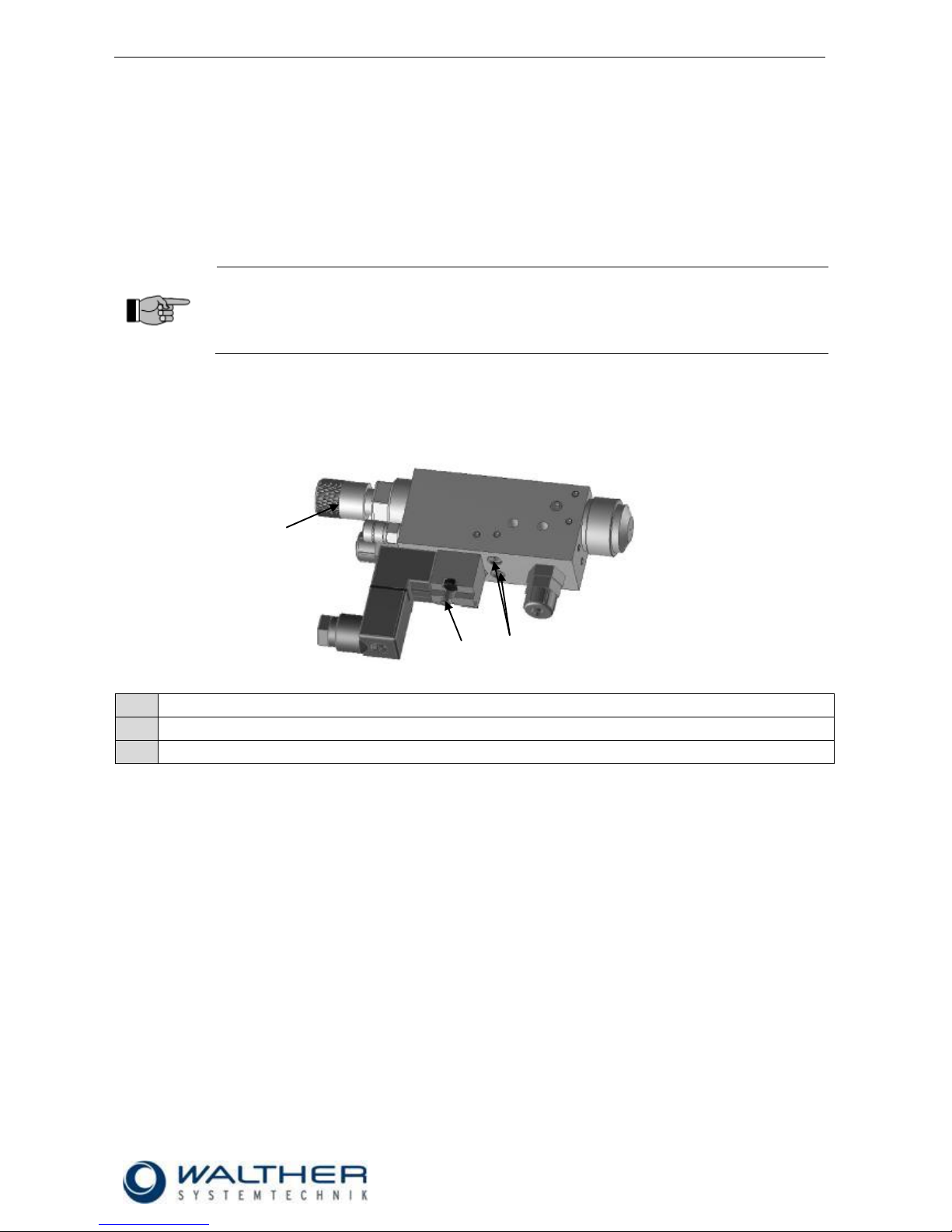
6.3 Operating Elements
1
Hand support release at solenoid valve (green head)
2
Regulating button for raster needle setting
3
Throttle screw for flat-jet adjustment
1 2 3
Page 13

Rev. 1.3
Assembly Instructions – Spray Valve SMS-05
Page 13 of 31
Walther Systemtechnik GmbH – D 76726 Germersheim
Telefon: +49 (0)7274-7022-0 Telefax: +49 (0)7274-7022-91
http://www.walther-2000.de – info@walther-2000.de
7 Maintenance and Repair
7.1 General Information
The spraying valves of the SMS-05 series are high precision tools. Always keep clean and observe minimum
instructions to maintain a long and useful life of valve. We recommend lubricating moveable parts regularly,
and greasing threads, especially the nozzle threads, when replacing or cleaning the nozzle. It is
recommended to use clean and filtered application fluid only. The control air should also be clean.
Maintenance also depends on the individual operating conditions and the type of media used.
CAUTION
Before starting any maintenance or repair work, ensure that all air-operated tools are
depressurized and disconnected from the air supply.
Before opening the spray valve it must be disconnected from the air and fluid supply.
Otherwise, ejected components can cause injuries.
Particularly when using the spray valve as color-marking unit, the spray cap should be removed before
longer standstills. The spray cap will be cleaned with a cloth and special dilution. Please make sure, that no
cloth fibers remain on the nozzle tip. After that the valve will be sprayed free by using the manual release at
the SPS or manual support release at the 3/2-way valve (green head).
7.2 Cleaning
IMPORTANT
Only use soft brushes for outside cleaning of the nozzle tips. Never use metal tools with
sharp edges.
Wash equipment thoroughly after use to remove residues and dirt, especially if needle (Pos.7.0.0) or sealing
bushing (6.1.0) or material nozzle (Pos.2.1.0) has to be exchanged.
7.3 Replacing the Sealing Screw
Loosen lock (6) and unscrew. (Attention: there is spring pressure in the lock)
Pull out nozzle needle (3) together with air valve (4) from the main body (1).
Use a suitable socket wrench for unscrewing the sealing screw (2) from the main body (1).
Screw in the new sealing screw (2); make sure that the sealing screw is slightly greased with technical
petroleum jelly (Vaseline).
Reassemble spray valve in reverse order.
Page 14

Rev. 1.3
Assembly Instructions – Spray Valve SMS-05
Page 14 of 31
Walther Systemtechnik GmbH – D 76726 Germersheim
Telefon: +49 (0)7274-7022-0 Telefax: +49 (0)7274-7022-91
http://www.walther-2000.de – info@walther-2000.de
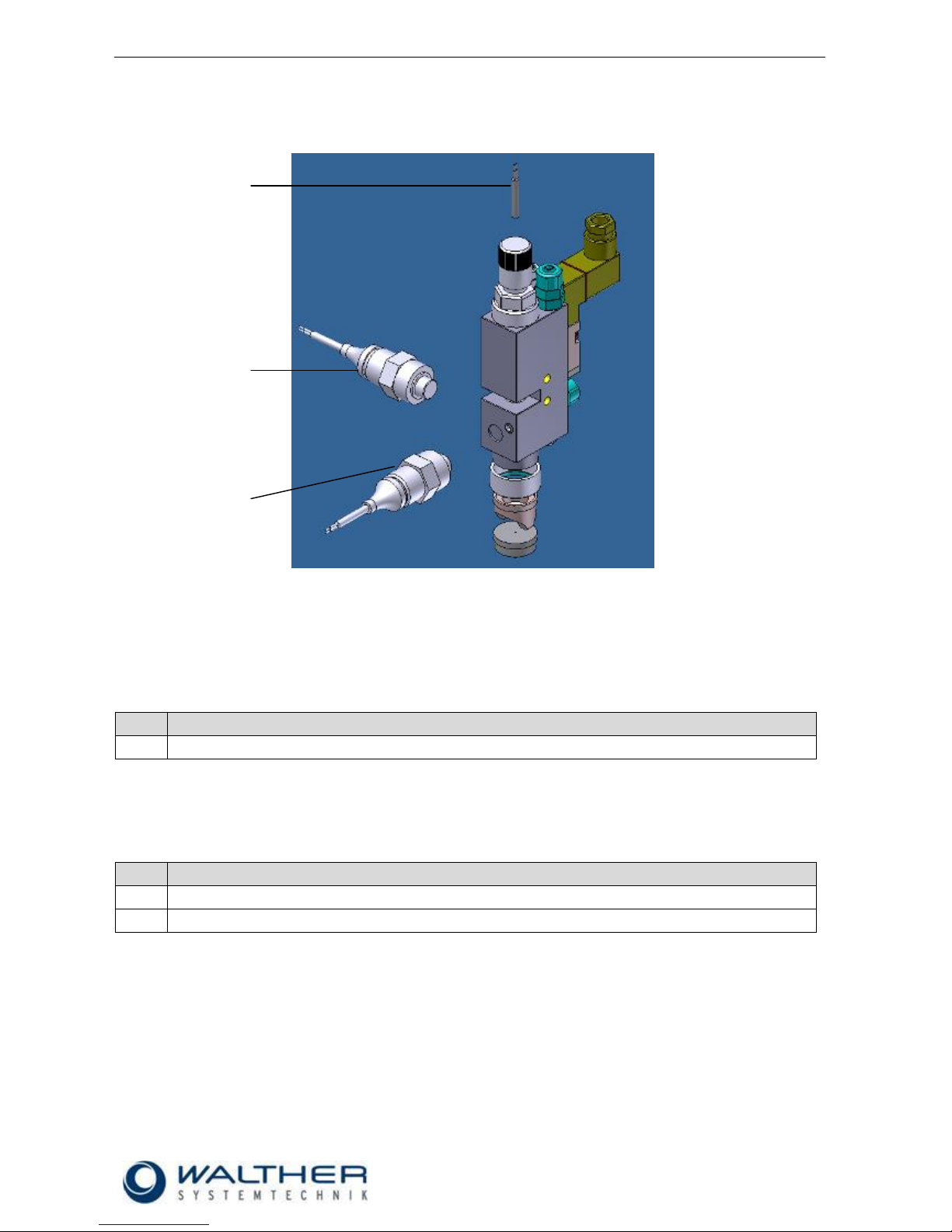
7.4 Replacing Nozzle and Needle
Loosen retainer ring (1) and remove air cap (2).
Unscrew raster lock (8) and remove. (Caution: there is spring pressure in the lock)
Make sure that the pressure spring (7) does not get lost.
Pull out the nozzle needle (6) together with the air valve (5) and unscrew nozzle (3).
Separate the old nozzle needle (6) from the air valve (5). Make sure that the smaller pressure spring
remains in the air valve.
Slightly grease new nozzle needle (6), connect to air valve and slightly grease; connect to air valve (6)
and insert in main body (4). Then clean needle tip from any grease residues.
Screw in new nozzle (3) into main body (4).
After that re-screw lock (8) onto main body (4).
Screw air cap (2) together with retainer ring (1) onto main body (4).
Perform a functional test of device after replacing nozzles and needles!
IMPORTANT
Nozzle set = Nozzle needle, nozzle and air cap (should always be replaced at the same
time)!
We do not recommend reusing old needles. Even slightly dirty needles can cause leakage of
the O-rings.
7.5 Replacing Sealing Elements (Raster Needle Sensor)
Remove the old sealing elements (1, 2, 3, 4, 6) from the sealing screw (5).
Carefully mount the new sealing elements (1, 2, 3, 4, 6) onto the sealing screw (5) – use technical
petroleum jelly (Vaseline).
Make sure that the sealing screw (5) is coated with technical petroleum jelly (Vaseline) so that the
sealing elements will not be damaged when the sealing screw is mounted in the main body.
Page 15

Rev. 1.3
Assembly Instructions – Spray Valve SMS-05
Page 15 of 31
Walther Systemtechnik GmbH – D 76726 Germersheim
Telefon: +49 (0)7274-7022-0 Telefax: +49 (0)7274-7022-91
http://www.walther-2000.de – info@walther-2000.de
The same procedure applies when replacing the sealing elements of the air valve.
IMPORTANT
O-rings and sealings screws are sensitive parts, too, and can be damaged.
Do not use any sharp or pointed metallic implements for inserting the sealings
The sealing screw in particular is a high-precision part with excellent sealing characteristics
which should not be exposed to impulses or pressures.
7.6 Maintenance for Use in Color Marking Systems (Normal Operation)
The spray cap must be cleaned with a cloth and special dilution every other day. Please make sure, that no
cloth fibers remain on the nozzle tip.
Every three months the spraying valve must be cleaned with the special dilution in the material area under
consideration of the steps below:
completely open ratchet needle lock (memorize setting for later use!)
take off air cap and screw out nozzle with an open-end wrench SW 6
IMPORTANT
Hold the spraying valve downwards when doing so, in order that the medium does not flow
into the air ducts. Collect the escaping medium in a container and dispose of it appropriately.
clean with a soft brush and the special dilution
reassemble the nozzle and the air cap after cleaning
readjust the setting of the raster needle
After system standstills (e.g. breaks overnight or on weekends) a cleaning cycle should be provided for,
which will blow the nozzle free. Use the system control to activate the cleaning cycle.
IMPORTANT
In order to avoid soiling, insert a dummy or cloth during the cleaning cycle!
After longer standstills (e.g. 2-3 weeks) the complete system must be cleaned prior to a restart. If
necessary, the material hoses and inlays (if any) of the pressure containers must be exchanged.
Every week the material pressure container must be opened in order to stir the color (if there is no
electric stirrer).
Every 3-4 months the material pressure container must be cleaned and the material hoses and
inlays must be exchanged.
Page 16

Rev. 1.3
Assembly Instructions – Spray Valve SMS-05
Page 16 of 31
Walther Systemtechnik GmbH – D 76726 Germersheim
Telefon: +49 (0)7274-7022-0 Telefax: +49 (0)7274-7022-91
http://www.walther-2000.de – info@walther-2000.de
7.7 Spare Parts
IMPORTANT
Only use original spare parts from the manufacturer!
Wrong or defective spare parts from other manufacturers can damage the device. If other
than original spare parts of the manufacturer will be used, all obligations from the manufacturer or his sales partners, such as guarantees, service contracts etc will be forfeited without
further notice.
7.8 Customer Service / Support
Walther Systemtechnik GmbH
Hockenheimer Straße 3
D-76726 Germersheim
Germany
fon ++49(0)7274-7022-0
fax ++49(0)7274-7022-91
Email info@walther-2000.de
Internet www.walther-2000.de
8 Troubleshooting
8.1 General Information
IMPORTANT
First check all supply lines for proper connection and serviceability.
In case of serious problems that cannot be resolved, please contact the Walther Systemtechnik GmbH
customer service.
8.2 Malfunctions:
Fault
Possible Cause
Action
Nozzle needle does
not open
No current supplied (slight click-sound on
solenoid valve)
Check voltage supply
Not enough control pressure available
Check if sufficient control air pressure is
available (5 - 6 bar).
Leakages
Check if O-ring (6.4) is defective
Nozzle needle sticky within sealing screw
(7.0 / 5.0)
Disassemble and clean
Needle stroke set too low
Check if needle stroke is correctly set
No atomizer air
Atomizer air pressure too low
Check is sufficient atomizer air pressure
is available at the spray valve
No material
discharged
Nozzle is clogged by material
Clean nozzle and needle
Material pressure too low
Check is sufficient material pressure is
applied to the spray valve
No sensor signal
with open needle
(needle detection)
Sensor defective; connection interrupted
Check cables / connections; if required,
replace sensor
Page 17

Rev. 1.3
Assembly Instructions – Spray Valve SMS-05
Page 17 of 31
Walther Systemtechnik GmbH – D 76726 Germersheim
Telefon: +49 (0)7274-7022-0 Telefax: +49 (0)7274-7022-91
http://www.walther-2000.de – info@walther-2000.de
8.3 Spray Image / Type of Defect
SPRAY IMAGE
PROBLEM
CAUSE
ACTION
Normal Spray Image (Flat jet)
Normal Spray Image (Round jet)
Spray image shaped
too much
upwards and
downwards
Spray image shaped
too much
upwards and
downwards
Spray image shaped
too much
upwards and
downwards
Spray image too much
left-sided or right-sided
Spray image too much
left-sided or right-sided
Spray image too much
left-sided or right-sided
Heavy application in the
middle of the spray image
Heavy application in the
middle of the spray
image
Heavy application in the
middle of the spray
image
Split
spray image
Split
spray image
Split
spray image
Page 18

Rev. 1.3
Assembly Instructions – Spray Valve SMS-05
Page 18 of 31
Walther Systemtechnik GmbH – D 76726 Germersheim
Telefon: +49 (0)7274-7022-0 Telefax: +49 (0)7274-7022-91
http://www.walther-2000.de – info@walther-2000.de
9 Taking out of Service
9.1 Short Interruption
A short interruption (15 min or more) has to be followed by a clean spraying.
IMPORTANT
Please follow the operating instructions!
9.2 Long-term Interruption
The following has to be observed for a long-term interruption of the device/machine:
Depressurize material supply lines
Take off air cap (2.0) and clean nozzle (3.0) with a special thinner and a soft cloth. Make sure that no
cloth fibers are left on the nozzle tip.
IMPORTANT
Please follow the maintenance instructions!
9.3 Shutdown of Device
The following is important for a shutdown of the machine / device:
Clean the spray valve with a special thinner.
IMPORTANT
Please follow the maintenance instructions!
Page 19

Rev. 1.3
Assembly Instructions – Spray Valve SMS-05
Page 19 of 31
Walther Systemtechnik GmbH – D 76726 Germersheim
Telefon: +49 (0)7274-7022-0 Telefax: +49 (0)7274-7022-91
http://www.walther-2000.de – info@walther-2000.de
10 Appendix
10.1 Dimensioned Drawing SMS-05
Page 20

Rev. 1.3
Assembly Instructions – Spray Valve SMS-05
Page 20 of 31
Walther Systemtechnik GmbH – D 76726 Germersheim
Telefon: +49 (0)7274-7022-0 Telefax: +49 (0)7274-7022-91
http://www.walther-2000.de – info@walther-2000.de
10.1.1 Spare Part Drawing SMS-05
IMPORTANT
If the spraying valve is equipped with a nozzle prolongation, the nozzle (3) and the nozzle
needle (7) are special versions.
Therefore, when ordering spare parts the article numbers for the nozzle and the nozzle needle must be inquired separately. Please do not use the article numbers of the standard version!
Nozzle set = Nozzle needle, nozzle and air cap (should always be exchanged at the same
time)
Page 21

Rev. 1.3
Assembly Instructions – Spray Valve SMS-05
Page 21 of 31
Walther Systemtechnik GmbH – D 76726 Germersheim
Telefon: +49 (0)7274-7022-0 Telefax: +49 (0)7274-7022-91
http://www.walther-2000.de – info@walther-2000.de
10.1.2 Spare Part Liste SMS-05
Dwg.-No.
Article No.
Qty
Description
1.0
97410028
1
Retainer ring
2.0 * 1
Air cap flat-jet/round jet Ø20 x 14.5mm
3.0 * 1
Nozzle, stainless steel, Ø 12 x 18mm, SW7
4.0
97510713
1
Main body, SMS-05, complete
5.0
5.1
5.2
5.3
5.4
5.5
97810103
97810102
97640026
97640019
97640052
97640415
1
1
2
1
1
1
Sealing screw SW11, complete
Sealing screw SW11
O-Ring Viton®
O-Ring Viton®
O-Ring Viton®
O-Ring Viton®
6.0
6.1
6.2
6.3
6.4
6.5
6.6
97380052
97380051
97640194
97640027
97640007
97640022
97820107
1
1
1
1
1
1
1
Air valve, ø 18 x 16mm complete
Air valve, ø 18 x 16mm
O-Ring Viton®
O-Ring Viton®
O-Ring Viton®
O-Ring Viton®
Pressure spring
7.0 * 1
Nozzle needle, complete
8.0
97820097
1
Pressure spring
8.1
97820044
1
Reinforced pressure spring
Standard
9.1
9.1.1
9.1.2
9.1.3
9.1.4
97900018
97220204
97610093
97320098
97620017
1
1
1
1
1
Raster needle lock
Raster locking screw
Needle stroke – raster head
Cable end ferrule
Locking washer
Raster needle detection
9.2
9.2.1
9.2.2
9.2.2.1
9.2.2.2
9.2.2.3
97900054
97220204
97610654
97250016
97320444
97410211
1
1
1
1
1
1
Raster needle lock
Raster lock screw
Needle stroke – raster head
Inductive proximity switch
Cable end ferrule
Counter nut
10.0
10.1
10.2
97380032
97380033
97640364
2
1
1
Throttle screw complete, M6
Throttle screw M6
O-Ring Viton®
11.0
97610249
2
Threaded pin
12.0
12.1
12.2
*
*
*
1
1
1
Solenoid valve 3/2-way, with plug
Solenoid valve 3/2-way
Appliance socket
13.0
*
1
Material connection
14.1
14.2
97610021
*
1
Threaded pin
Material circulation (Option 1)
15.1
15.2
97610021
*
1
Threaded pin
Material circulation (Option 2)
16.0
*
1
Connection for control air
17.0
*
1
Connection for atomizer air
* Article numbers can be found on the following pages.
Page 22

Rev. 1.3
Assembly Instructions – Spray Valve SMS-05
Page 22 of 31
Walther Systemtechnik GmbH – D 76726 Germersheim
Telefon: +49 (0)7274-7022-0 Telefax: +49 (0)7274-7022-91
http://www.walther-2000.de – info@walther-2000.de
10.2 Article Numbers for Air Caps
2.0
Air cap, Flat-jet, Standard, 60° (Ø20x14.5mm)
Artikel-Nr.
Description
97310234
Air cap, Flat-jet, 0.2-1.0mm
97310235
Air cap, Flat-jet, 1.2-1.5mm
97310236
Air cap, Flat-jet, 1.8-2.0mm
97310237
Air cap, Flat-jet, 2.5mm
2.0
Air cap, Flat-jet, Standard, 90° (Ø20x14.5mm)
Artikel-Nr.
Description
97310238
Air cap, Flat-jet, 0.2-1.0mm
97310239
Air cap, Flat-jet, 1.2-1.5mm
97310240
Air cap, Flat-jet, 1.8-2.0mm
97310241
Air cap, Flat-jet, 2.5mm
2.0
Air cap, Round-jet, KLS, 15° (Ø20x11mm)
Artikel-Nr.
Description
97310084
Air cap, Round-jet, KLS 0.2-1.0mm
97310085
Air cap, Round-jet, KLS 1.2-1.5mm
97310086
Air cap, Round-jet, KLS 1.8-2.0mm
97310250
Air cap, Round-jet, KLS 2.5mm
2.0
„B“ = TEFLON coating
97310114
Air cap, Round-jet, KLS/B 0.2-1.0mm
97310115
Air cap, Round-jet, KLS/B 1.2-1.5mm
97310233
Air cap, Round-jet, KLS/B 1.8-2.0mm
2.0
Marking Air cap, Round-jet° (Ø20x18mm)
Artikel-Nr.
Description
97310578
Marking cap 0.2-0.5mm
97310727
Marking cap 0.8-1.0mm
2.0
Special spin air cap, round jet
Artikel-Nr.
Description
97310197
Special spin 0.2-2.0mm
2.0
Air cap, Einhorn, KLS, 45° (Ø20x14.5mm)
Artikel-Nr.
Description
97310087
Air cap, Einhorn, KLS 0.2-1.0mm
97310088
Air cap, Einhorn, KLS 1.2-1.5mm
97310089
Air cap, Einhorn, KLS 1.8-2.0mm
Page 23

Rev. 1.3
Assembly Instructions – Spray Valve SMS-05
Page 23 of 31
Walther Systemtechnik GmbH – D 76726 Germersheim
Telefon: +49 (0)7274-7022-0 Telefax: +49 (0)7274-7022-91
http://www.walther-2000.de – info@walther-2000.de
10.3 Article Numbers for Nozzles
3.0
Nozzle, Standard, stainless steel (Ø12x18mm)
Artikel-Nr.
Description
97210110
Nozzle, Standard, 0.2mm
97210111
Nozzle, Standard, 0.3mm
97210112
Nozzle, Standard, 0.5mm
97210113
Nozzle, Standard, 0.8mm
97210114
Nozzle, Standard, 1.0mm
97210115
Nozzle, Standard, 1.2mm
97210116
Nozzle, Standard, 1.5mm
97210117
Nozzle, Standard, 2.0mm
97210118
Nozzle, Standard, 2.5mm
3.0
Nozzle, KLS, stainless steel (Ø12x17.2mm)
Artikel-Nr.
Description
97210119
Nozzle, KLS, 0.2mm
97210120
Nozzle, KLS, 0.3mm
97210121
Nozzle, KLS, 0.5mm
97210122
Nozzle, KLS, 0.8mm
97210123
Nozzle, KLS, 1.0mm
97210124
Nozzle, KLS, 1.2mm
97210125
Nozzle, KLS, 1.5mm
97210126
Nozzle, KLS, 2.0mm
97210564
Nozzle, KLS, 2.5mm
3.0
„B“ = TEFLON coating
97210558
Nozzle, KLS/B, 0.3mm
97210557
Nozzle, KLS/B, 0.5mm
97210697
Nozzle, KLS/B, 0.8mm
97210560
Nozzle, KLS/B, 1.0mm
97210215
Nozzle, KLS/B, 1.5mm
97210559
Nozzle, KLS/B, 2.0mm
3.0
Nozzle, KLS, spin, stainless steel 30° (Ø12x17.3mm)
Artikel-Nr.
Description
97210805
Nozzle, KLS, 0.3mm
97210806
Nozzle, KLS, 0.5mm
97210807
Nozzle, KLS, 0.8mm
97210808
Nozzle, KLS, 1.0mm
97211391
Nozzle, KLS, 1.2mm
97210809
Nozzle, KLS, 1.5mm
97210810
Nozzle, KLS, 2.0mm
97211467
Nozzle, KLS, 2.5mm
Page 24

Rev. 1.3
Assembly Instructions – Spray Valve SMS-05
Page 24 of 31
Walther Systemtechnik GmbH – D 76726 Germersheim
Telefon: +49 (0)7274-7022-0 Telefax: +49 (0)7274-7022-91
http://www.walther-2000.de – info@walther-2000.de
3.0
Marking nozzle, stainless steel 8°(Ø8x18mm)
Artikel-Nr.
Description
97212055
Marking nozzle 0.2mm
97211875
Marking nozzle 0.3mm
97212025
Marking nozzle 0.4mm
97211461
Marking nozzle 0.5mm
97212146
Marking nozzle 0.8mm
3.0
Nozzle, special spin, stainless steel (Ø12x18mm)
Artikel-Nr.
Description
97210483
Nozzle, special spin, 0.2mm
97210484
Nozzle, special spin, 0.3mm
97210482
Nozzle, special spin, 0.5mm
97210485
Nozzle, special spin, 0.8mm
97211030
Nozzle, special spin, 1.0mm
97212510
Nozzle, special spin, 1.5mm
97212397
Nozzle, special spin, 2.0mm
10.4 Article Numbers for Nozzle Needles
7.0
Nozzle needle complete, Standard, marking, special
spin (Ø3x72.5mm)
Artikel-Nr.
Description
97111210
Nozzle needle, Standard, 0.2/0.3mm
97111211
Nozzle needle, Standard, 0.5mm
97111212
Nozzle needle, Standard, 0.8mm
97111209
Nozzle needle, Standard, 1.0mm
97111240
Nozzle needle, Standard, 1.2mm
97111241
Nozzle needle, Standard, 1.5mm
97111242
Nozzle needle, Standard, 1.8/2.0mm
7.0
Nozzle needle complete, KLS (Ø3x77.5mm)
Artikel-Nr.
Description
97112124
Nozzle needle, KLS, 0.2/0.3mm
97111631
Nozzle needle, KLS, 0.5mm
97111632
Nozzle needle, KLS, 0.8/1.0mm
97111971
Nozzle needle, KLS, 1.5mm
Page 25

Rev. 1.3
Assembly Instructions – Spray Valve SMS-05
Page 25 of 31
Walther Systemtechnik GmbH – D 76726 Germersheim
Telefon: +49 (0)7274-7022-0 Telefax: +49 (0)7274-7022-91
http://www.walther-2000.de – info@walther-2000.de
10.5 Article Numbers for Valves
12.0
3/2-way Solenoid valve (complete with plug and
seal)
Artikel-Nr.
Description
97150104
Magnetic valve 24V / DC/2.5 W (with manual trigger)
97150017
Magnetic valve 110V/50Hz/1.5W
97150016
Magnetic valve 220V/50Hz/1.5W
12.0
Sealing Frame + Gasket
Artikel-Nr.
Description
97640109
Sealing frame for solenoid valves 97150017 and
97150016
97640378
Sealing frame for solenoid valve 97150104
97640108
Gasket for magnetic valves 97150017 and 97150016
97640379
Gasket for magnetic valve 97150104
12.0
3/2-way Solenoid valve
Artikel-Nr.
Description
97150004
Magnetic valve 110V/50Hz/1.5W
97150003
Magnetic valve 220V/50Hz/1.5W
97150103
Magnetic valve 24 V/DC/ 2W (with manual trigger)
12.0
Screws
Artikel-Nr.
Description
97610343
Cylinder bolt M3 x 16, black for 97150017 and
97150016
97610342
Cylinder bolt M3 x 18, black for 97150104
10.6 Article Numbers Threaded Joints
13.0
Screwed joint for connection „Material M“
Artikel-Nr.
Description
97220022
Straight screwed joint 1/8" - 6/40.2mm
97220243
Straight screwed joint 1/8" - 6/40.2mm
97220548
Straight screwed joint 1/8" - 6/40.2mm
97220552
Straight screwed joint 1/8" - 6/40.2mm
14.2
Screwed joint for connection „Material circulation
(Option 1)“
Artikel-Nr.
Description
97220089
L-plug-in Screwed joint QSL M5 - 6/4
97220573
L-plug-in Screwed joint QSL M5 - 6/4
97220551
L-plug-in Screwed joint QSL M5 - 6/4
97220454
L-plug-in Screwed joint QSL M5 - 6/4
Page 26

Rev. 1.3
Assembly Instructions – Spray Valve SMS-05
Page 26 of 31
Walther Systemtechnik GmbH – D 76726 Germersheim
Telefon: +49 (0)7274-7022-0 Telefax: +49 (0)7274-7022-91
http://www.walther-2000.de – info@walther-2000.de
15.2
Screwed joint for connection „Material circulation
(Option 2)“
Artikel-Nr.
Description
97220089
L-plug-in Screwed joint QSL M5 - 6/4
97220573
L-plug-in Screwed joint QSL M5 - 6/4
97220551
L-plug-in Screwed joint QSL M5 - 6/4
97220454
L-plug-in Screwed joint QSL M5 - 6/4
16.0
Screwed joint for connection „Control air SL“
Artikel-Nr.
Description
97220089
Screwed joint M5 - 6/4, complete, SW 8 x 19mm
97220573
Plug-in Screwed joint QS M5, 6/4
97220551
Plug-in Screwed joint M5, 4/3
97220089
Threaded joint complete (SW 8x19mm)
17.0
Screwed joint for connection „Atomizing air ZL“
Artikel-Nr.
Description
97220022
Straight Screwed joint 1/8" - 6/4
97220243
Straight Screwed joint 1/8" - 8/6
97220548
Plug-in Screwed joint QS 1/8" - 6/4
97220022
Threaded joint (SW 13x28mm)
10.7 Wear-and-Tear Parts
Sealing set complete for SMS-05
Consisting of:
# Pos.10.2 , 1 each
# Pos.5.2 , 1 each
# Pos.5.3 , 1 each
# Pos.5.4 , 1 each
# Pos.5.5 , 1 each
# Pos.6.2 , 1 each
# Pos.6.3 , 1 each
# Pos.6.4 , 1 each
# Pos.6.5 , 1 each
Artikel-Nr.
Description
97640475
Sealing set for SMS-05, VITON
97640899
Sealing set for SMS-05, EPDM
Page 27

Rev. 1.3
Assembly Instructions – Spray Valve SMS-05
Page 27 of 31
Walther Systemtechnik GmbH – D 76726 Germersheim
Telefon: +49 (0)7274-7022-0 Telefax: +49 (0)7274-7022-91
http://www.walther-2000.de – info@walther-2000.de
10.8 Accessories
Figure
Article Number
Description
97xxxxxx
Nozzle extension
(see product catalog ACCESSORIES)
97410042
Retainer ring hexagonal
97410059
Retainer ring stainless steel
979565.002
Heating plate
(see product catalog ACCESSORIES)
97PA21G-XX
Pressure sensor
(see product catalog „Checking“)
97947xxx
Counter
97800037
Pneumatic Needle-Stroke Adjustment
979444
Cleaning set
(see also Product catalog ACCESSORIES)
Page 28

Rev. 1.3
Assembly Instructions – Spray Valve SMS-05
Page 28 of 31
Walther Systemtechnik GmbH – D 76726 Germersheim
Telefon: +49 (0)7274-7022-0 Telefax: +49 (0)7274-7022-91
http://www.walther-2000.de – info@walther-2000.de
Figure
Article Number
Description
97320602
Centering sleeve for an exact positioning of the valve
10.8.1 Center hole for Centering sleeve 97320602
WICHTIG
If a Centering sleeve is retrofitted to an existing valve, the valve must be returned to us for
retrofitting of Center hole.
Page 29
Rev. 1.3
Assembly Instructions – Spray Valve SMS-05
Page 29 of 31
Walther Systemtechnik GmbH – D 76726 Germersheim
Telefon: +49 (0)7274-7022-0 Telefax: +49 (0)7274-7022-91
http://www.walther-2000.de – info@walther-2000.de
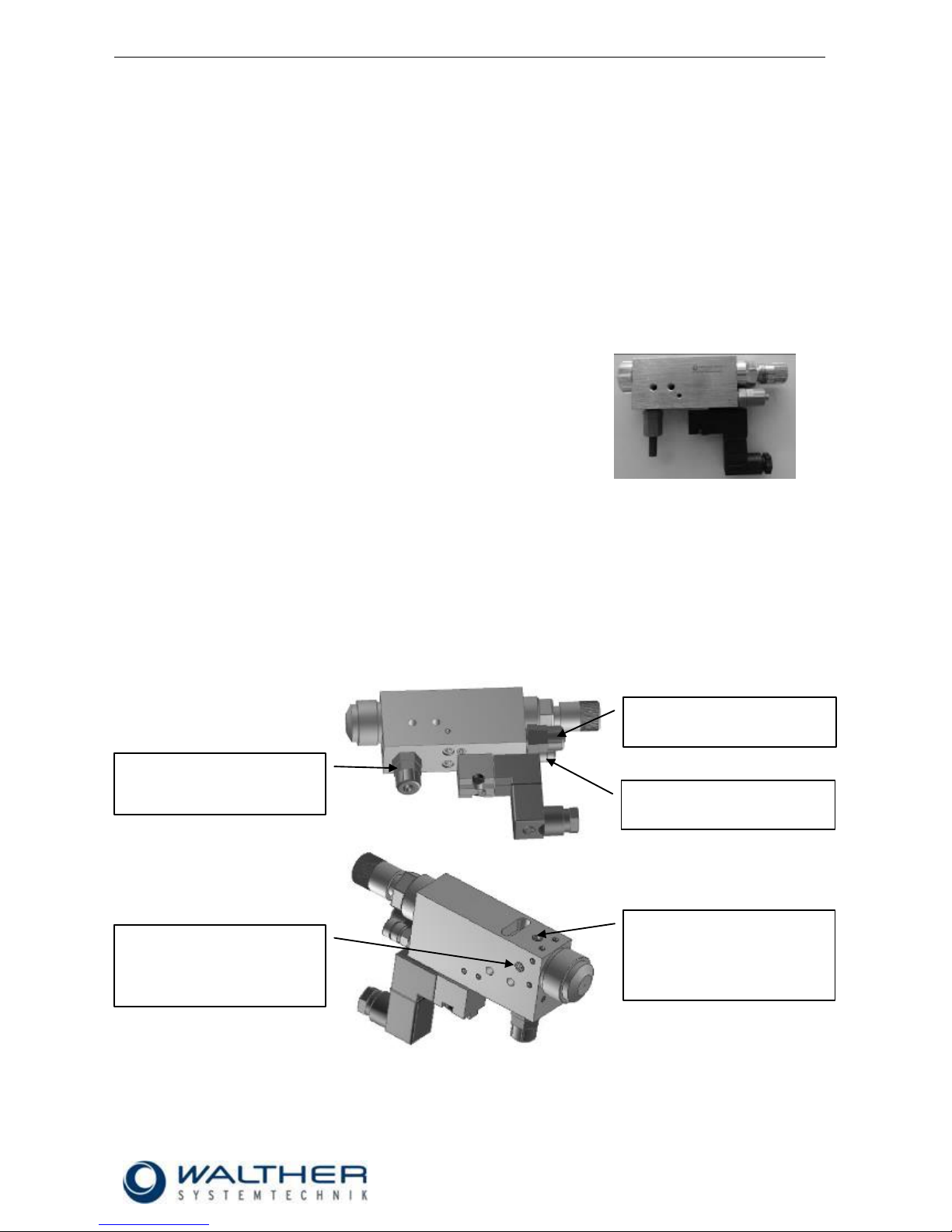
10.8.2 Add-on Elements
Needle Sensor
The mounting of the needle sensor will be made factory-side. It will be integrated in the raster needle lock
(Pos. 15.4 Spare Part List). If ordered as spare part, please note that a complete raster needle lock will be
delivered as the initiator has to be set at the factory and also glued in.
Pos.
Description
1
Raster needle sensor
Pressure Sensor
The installation of the pressure sensor will be made factory-side. Its actual position can be either at the side
(left or right) or on top. Please refer to the assembly instructions „Pressure Sensors 97PA-21x-xxx“ for additional information.
Pos.
Description
2
Pressure sensor mounted on top of the spray valve
3
Pressure sensor mounted at the right side of the spray valve
Hotplate
The heating plate will be mounted factory-side. Its actual position will be at the side (left / right). Please see
the description „Heating and Accessories“ for additional information.
3 2 1
Page 30
Rev. 1.3
Assembly Instructions – Spray Valve SMS-05
Page 30 of 31
Walther Systemtechnik GmbH – D 76726 Germersheim
Telefon: +49 (0)7274-7022-0 Telefax: +49 (0)7274-7022-91
http://www.walther-2000.de – info@walther-2000.de
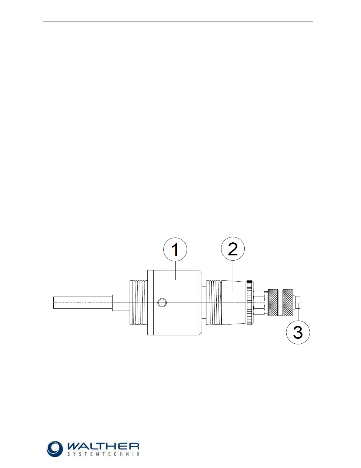
10.8.3 Description of Pneumatic Needle-Stroke Adjustment 97800037
Description of Function
The pneumatic Needle Stroke Adjustment (PNA) is used for a remote-controlled change between two needle-stroke settings.
The front regulating screw (1; see pic.) determines the minimum needle stroke of the spraying device for a
PNA with applied pressure. The back regulating screw (2; see pic.) determines the additional (maximum)
needle stroke for a PNA without applied pressure.
Setting
For a pre-setting, the front regulating screw (1; see pic.) will be turned back (left turn) until no more raster
steps are possible. After that the back regulating screw (2; see pic.) will be turned to the front until stop (right
turn). Strictly follow this procedure to ensure a correct setting of both needle positions.
The spray application has to be activated/released in order to adjust both needle positions. The discharged
medium will be set to the desired minimum quantity (low needle stroke) through the front regulating screw (1;
see pic.). Then the desired maximum quantity (large stroke) will be set by turning back (left turn) of the back
regulating screw.
Important!
The PNA has to permit an opening of the needle in both positions (large and small stroke). In no case will it
be used to close the needle.
This is exclusively performed by the controls of the spray valve!
When a pressure of 6 bar will be applied to the PNA at the hose nipple (3; see pic.), the small needle stroke
has been set; the large stroke is set without pressure.
Operation
You can switch between the stroke settings during operation via the hose nipple (3):
- Air pressure = 6 bar
- With applied air = low stroke
- With air turned off = large stroke
Page 31

Rev. 1.3
Assembly Instructions – Spray Valve SMS-05
Page 31 of 31
Walther Systemtechnik GmbH – D 76726 Germersheim
Telefon: +49 (0)7274-7022-0 Telefax: +49 (0)7274-7022-91
http://www.walther-2000.de – info@walther-2000.de
Pos.
Article No.
Qty
Description
1.0
97610172
1
Raster head
1.1
97610170
1
Regulating hollow spindle
1.2
97820000
1
Pressure spring
1.3
97320022
1
Cylinder pin DIN 6325
1.4
97320196
1
Regulating button
3.0
97710021
1
Piston complete
3.1
97320145
1
Piston rod
3.2
97710020
1
Piston
3.3
97640007
1
O-Ring Viton®
4.0
97320198
1
Air cylinder, complete
4.1
97610031
3
Threaded pin DIN 914
4.2
97320193
1
Air cylinder with knurl
4.3
97320144
1
Raster hollow screw
4.4
97640027
1
O-Ring Viton®
5.0
97610173
1
Raster head
5.1
97610171
1
Regulating hollow spindle
5.2
97820000
1
Pressure spring
5.3
97320022
1
Cylinder pin DIN 6325
5.4
97320197
1
Regulating button
 Loading...