


Rev. 1.4
Assembly Instructions – Spray Valve SMS-11
Page 1 of 28
Walther Systemtechnik GmbH – D 76726 Germersheim
Telefon: +49 (0)7274-7022-0 Telefax: +49 (0)7274-7022-91
http://www.walther-2000.de – info@walther-2000.de
Assembly Instructions
AUTOMATIC Spray Valve SMS-11
Article Number: S11-….
Figure: Spray Valve SMS-11 Standard with flat-jet air cap and raster-needle lock
NOTE
Please read the Assembly Instructions carefully before first using the incomplete device and
strictly adhere to the instructions!
The incomplete device may only be worked with and worked on by persons who are familiar
with the assembly instructions and the current regulations for industrial safety and accident
prevention.
Always keep a translated version of the “Original Assembly Instructions“ at the incomplete device!
The instructions have to be available anytime!

Rev. 1.4
Assembly Instructions – Spray Valve SMS-11
Page 2 of 28
Walther Systemtechnik GmbH – D 76726 Germersheim
Telefon: +49 (0)7274-7022-0 Telefax: +49 (0)7274-7022-91
http://www.walther-2000.de – info@walther-2000.de
Table of Contents
Page
EC DECLARATION OF INCORPORATION ....................................................................................................................... 4
1 INTRODUCTION ................................................................................................................................................. 5
1.1 TARGET GROUP OF THE ASSEMBLY INSTRUCTIONS ............................................................................................................ 5
1.2 LIST OF SIGNS AND SYMBOLS ....................................................................................................................................... 5
2 SAFETY............................................................................................................................................................... 5
2.1 GENERAL INFORMATION ............................................................................................................................................. 5
2.2 DANGERS FROM RESIDUAL ENERGY ............................................................................................................................... 5
2.3 WARRANTY AND LIABILITY ........................................................................................................................................... 5
2.4 CORRECT USE ........................................................................................................................................................... 6
2.5 INCORRECT USE ........................................................................................................................................................ 6
2.6 REQUIRED QUALIFICATION OF PERSONNEL ...................................................................................................................... 6
3 TRANSPORT ....................................................................................................................................................... 6
3.1 PACKAGING .............................................................................................................................................................. 6
3.2 TASKS BEFORE TRANSPORT .......................................................................................................................................... 6
4 DESCRIPTION OF FUNCTION .............................................................................................................................. 7
4.1 DESIGNATED PURPOSE OF THE DEVICE ........................................................................................................................... 7
4.2 TECHNICAL DATA ....................................................................................................................................................... 7
4.3 TYPE LABEL .............................................................................................................................................................. 7
5 MOUNTING AND START OF OPERATION ............................................................................................................ 8
5.1 HOSE MOUNTING...................................................................................................................................................... 8
5.1 RASTER-NEEDLE SENSOR ............................................................................................................................................ 9
5.1.1 Setting of Sensor (Raster-Needle) ............................................................................................................... 9
6 OPERATION ..................................................................................................................................................... 10
6.1 GENERAL INFORMATION ........................................................................................................................................... 10
6.2 OPERATION INSTRUCTIONS / OPERATING CONDITIONS .................................................................................................... 10
6.3 FUNCTION – ADJUSTING THE JET WIDTH ...................................................................................................................... 11
7 SERVICE, REPAIR AND MALFUNCTION ............................................................................................................. 12
7.1 GENERAL INFORMATION ........................................................................................................................................... 12
7.2 CLEANING .............................................................................................................................................................. 12
7.3 SPARE PARTS .......................................................................................................................................................... 12
7.4 REPLACING NOZZLE AND NOZZLE NEEDLE .................................................................................................................... 13
7.5 REPLACING THE SEALING ELEMENTS ............................................................................................................................ 14
7.6 TROUBLESHOOTING.................................................................................................................................................. 15
7.7 GENERAL INFORMATION ........................................................................................................................................... 15
7.8 CUSTOMER SERVICE / SUPPORT .................................................................................................................................. 15
7.9 MALFUNCTIONS ...................................................................................................................................................... 15
7.10 SPRAY IMAGES / TYPES OF DEFECTS ........................................................................................................................ 16
8 TAKING OUT OF SERVICE ................................................................................................................................. 17
8.1 SHORT INTERRUPTION .............................................................................................................................................. 17
8.2 LONG-TERM INTERRUPTION ....................................................................................................................................... 17
8.3 SHUTDOWN OF DEVICE ............................................................................................................................................. 17
8.4 DISPOSAL ............................................................................................................................................................... 17
9 APPENDIX ........................................................................................................................................................ 18
9.1 DIMENSIONED DRAWING OF SMS-11 (STANDARD AND WITH RASTER-NEEDLE SENSOR) ....................................................... 18
9.1.1 Dimensioned Drawing of SMS-11 with Clamping Holder (Standard) ........................................................ 19
9.1.2 Dimensioned Drawing of SMS-11 with Quick-Change Board (Standard) .................................................. 19
9.2 SPARE PART DRAWING FOR SMS-11 (STANDARD) ......................................................................................................... 20
9.2.1 Spare Part List for SMS-11 (Standard) ....................................................................................................... 21

Rev. 1.4
Assembly Instructions – Spray Valve SMS-11
Page 3 of 28
Walther Systemtechnik GmbH – D 76726 Germersheim
Telefon: +49 (0)7274-7022-0 Telefax: +49 (0)7274-7022-91
http://www.walther-2000.de – info@walther-2000.de
9.3 SPARE PART LIST FOR SMS-11 (RASTER-NEEDLE SENSOR) .............................................................................................. 22
9.3.1 Spare Part List for SMS-11 (Raster-Needle Sensor) ................................................................................... 23
9.4 WEAR-AND-TEAR PARTS ........................................................................................................................................... 23
9.5 ARTICLE NUMBERS FOR AIR CAPS ............................................................................................................................... 24
9.6 ARTICLE NUMBERS FOR NOZZLES ................................................................................................................................ 25
9.7 ARTICLE NUMBERS FOR NOZZLE NEEDLES ..................................................................................................................... 26
9.8 SCREW JOINTS ........................................................................................................................................................ 26
9.9 ACCESSORIES .......................................................................................................................................................... 27
9.9.1 Center Hole for Centering Sleeve 97320602 .............................................................................................. 28

Rev. 1.4
Assembly Instructions – Spray Valve SMS-11
Page 4 of 28
Walther Systemtechnik GmbH – D 76726 Germersheim
Telefon: +49 (0)7274-7022-0 Telefax: +49 (0)7274-7022-91
http://www.walther-2000.de – info@walther-2000.de
EC Declaration of Incorporation
in accordance with EU Machinery Directive 2006/42/EU, dated 17 May 2006, Appendix II B
We herewith confirm that the below mentioned incomplete device meets the basic requirements for safety
and health as stated in EU Machinery Directive 2006/42/EU for its design and construction as well as for the
configuration released by us on the market. This machine component will not be operated before it has been
determined that the incomplete system where the machine component will be installed also meets the
requirements of the Directive (2006/42/EG).
Manufacturer
Walther Systemtechnik GmbH
Hockenheimer Straße 3
D- 76726 Germersheim
Description
Spray Valve SMS-11, Article No. S11-…
We also declare the conformity with other, product-relevant directives/guidelines:
Mach. Direct. 2006/42/EU App. I, Clause: 1.1.2, 1.1.3, 1.1.5, 1.1.6, 1.3.2, 1.3.3,
1.3.4, 1.5.8, 1.5.9
EMC- Directive 2014/30/EU, dated 26. February 2014
Applied harmonized standards, in particular:
DIN EN ISO 12100 Safety of Machinery – General Design Principles –
Risk Assessment and Risk Reduction (ISO
12100:2010)
In addition, we also confirm that the special documentation according to Appendix VII Part B has
been prepared.
The manufacturer, respectively his authorized representative obligates himself to submit this documentation
to the market surveillance authorities, if requested.
This EC Declaration of Incorporation becomes invalid if the incomplete device will be altered or changed
without consent of Walther Systemtechnik GmbH.
Authorized representative for Technical Documentation:
Stefan Hirl, Hockenheimer Straße 3, D- 76726 Germersheim
Germersheim, 16 May 2018
(Place, Date) (Stefan Hirl, Management)
Rev. 1.4
Assembly Instructions – Spray Valve SMS-11
Page 5 of 28
Walther Systemtechnik GmbH – D 76726 Germersheim
Telefon: +49 (0)7274-7022-0 Telefax: +49 (0)7274-7022-91
http://www.walther-2000.de – info@walther-2000.de
1 Introduction
1.1 Target Group of the Assembly Instructions
Operating Personnel
Maintenance Personnel
1.2 List of Signs and Symbols
The assembly instructions warn users of operations which may put their health at risk.
The warnings are indicated by combinations of text and symbols as follows:
DANGER
Describes a potentially dangerous situation.
Death, grievous bodily harm or severe material damage WILL occur if the respective
measures of precaution have not been taken.
WARNING
Describes a potentially dangerous situation.
Death, grievous bodily harm or severe material damage MAY occur if the respective
measures of precaution have not been taken.
CAUTION
Describes a potentially dangerous situation.
Slight injuries CAN occur if the respective measures of precaution have not been taken. This
signal word is also used to describe possible property damages.
IMPORTANT
Indicates tips for usage and other particularly useful information.
No dangerous situation.
2 Safety
2.1 General Information
The construction of this device is according to the latest technology and is absolutely reliable. The individual
components as well as the complete device are continuously checked by our quality management team.
2.2 Dangers from Residual Energy
Please instruct the operating personnel on the respective measures to be taken against the occurrence of
mechanical, hydraulic, pneumatic and electric / electronic residual energies.
2.3 Warranty and Liability
According to the conditions laid down by the German Engineering Association (VDMA), Walther Systemtechnik GmbH has a guarantee of 12 months under normal European operating conditions on its own
parts (spare parts are excluded); or according to the conditions of the manufacturer.
This guarantee can only be granted by Walther Systemtechnik GmbH, if:
the user has thorough knowledge of the content of the assembly instructions;
the user follows the instructions and notes contained in the assembly instructions;
the user does not rebuild or make changes on parts of the device without prior consent of WST Sys-
temtechnik GmbH.

Rev. 1.4
Assembly Instructions – Spray Valve SMS-11
Page 6 of 28
Walther Systemtechnik GmbH – D 76726 Germersheim
Telefon: +49 (0)7274-7022-0 Telefax: +49 (0)7274-7022-91
http://www.walther-2000.de – info@walther-2000.de
2.4 Correct Use
This device is a needle valve and will be used for processing materials which can be sprayed in continuous
or intermitting operation.
2.5 Incorrect Use
Operating the device with insufficient knowledge about the operation, maintenance and care of the de-
vice.
Making changes, extensions or alterations on the device that may hamper its safety without the prior
consent of Walther Systemtechnik GmbH.
Operating the device with defective safety installations or not properly attached or malfunctioning safety
devices.
Using unsuitable materials.
Handling the device while energized.
Under no circumstances shall aggressive media such as acids, alkaline solutions, detergents, chemicals
or others be sprayed. If you are not sure, please contact the manufacturer if a certain spray medium is
suitable for this device.
2.6 Required Qualification of Personnel
Only trained and instructed personnel may conduct work on the equipment.
The responsibilities of the personnel for assembly work, operation, repair work or maintenance work must be
clearly assigned to individuals!
Persons in training may work with the equipment only under supervision of an experienced person.
Personnel
Task
Instructed
Personnel
Personnel with
Technical
Qualification
Specialist
Supervisor
Packaging and Transport
X
Mounting and Start of
Operation
X X
Operation
X
Service, Maintenance and
Troubleshooting
X X
Shutdown and Disposal
X X
Assigning Personnel
X
3 Transport
3.1 Packaging
The type of packaging depends on the individual mode of shipping. If not separately contracted, the
packaging is in accordance with the rules and regulations of Walther Systemtechnik GmbH.
3.2 Tasks before Transport
The following has to be done before transport:
Disconnect all power lines.
The actual transport of the incomplete device and its individual parts requires special care in order to prevent
damages from external forceful impact or careless on- and off-loading. Depending on the mode of
transportation, suitable transport and load securing has to be selected. The incomplete device will be aligned
and leveled by appropriate fastening elements.
Rev. 1.4
Assembly Instructions – Spray Valve SMS-11
Page 7 of 28
Walther Systemtechnik GmbH – D 76726 Germersheim
Telefon: +49 (0)7274-7022-0 Telefax: +49 (0)7274-7022-91
http://www.walther-2000.de – info@walther-2000.de
4 Description of Function
4.1 Designated Purpose of the Device
CAUTION
The use of other media can cause functional failures, damages or even the destruction of the
device.
Danger from ejected medium under high pressure. Depending on the pressure for
atomization and material, the spraying process can be accompanied by loud noise! We
recommend wearing ear protection.
The AUTOMATIC SMS-11 valve is a pneumatic device and is suitable for the application of greases, oils,
separating agents or colors. It will be opened by control air and will be closed by a needle spring in case of
failure or turn-off of the control air. The spray medium will be supplied into the valve from a pressured
container or via a pump. The separately controlled spray air distributes the material into the actual spray jet,
for which the jet width can be individually adjusted. The discharge from the nozzle will be performed through
the selected special air cap as flat or round jet. Depending on the viscosity of the medium to be applied, the
application result can be individually adjusted through the nozzle size, the atomized air pressure or also the
material supply pressure as well as the jet width settings. Supply of spray air, control air and material is
performed through three hoses, respectively four hoses if the jet width settings are performed vie remote
control. The function of the needle is: opening by air pressure / closing by spring pressure. The SMS-11 is
optionally available with raster-needle sensor and material circulation.
The SMS-11 is optionally available with raster-needle sensor, nozzle extensions, clamping holder,
quick-change board, heating plate and material circulation.
4.2 Technical Data
General Data
Dimensions [mm] = ca. 50 x 30 x 72,5 (Standard)
= ca. 50 x 45 x 72,5 (Standard with clamping holder)
= ca. 50 x 45 x 72,5 (Standard with quick-change board/adapter)
= ca. 50 x 30 x 102 (with raster-needle sensor)
Weight [g] = ca. 300
Air consumption, manual = ca. 111ltr./min. (at 3bar, 0,3mm nozzle, flat-jet cap and 2m
jet width adjustment hose length
Air consumption, remote control = ca. 133ltr./min. (at 3bar, 0,3mm nozzle, flat-jet cap and 2m
jet width adjustment hose length
Energy Supply
Control air pressure [bar] = min. 3,5 – max. 6
Atomizer air pressure [bar] = 0,5 - 6
Material pressure [bar] = max. 10
4.3 Type Label
The type label has been etched into the casing. The serial number was
hammered into the type label.
Rev. 1.4
Assembly Instructions – Spray Valve SMS-11
Page 8 of 28
Walther Systemtechnik GmbH – D 76726 Germersheim
Telefon: +49 (0)7274-7022-0 Telefax: +49 (0)7274-7022-91
http://www.walther-2000.de – info@walther-2000.de
5 Mounting and Start of Operation
CAUTION
Hazard from ejected medium under high pressure. We highly recommend eye protection.
Depending upon the pressure for atomization and material, the spraying process can be
accompanied by loud noise! If necessary, we recommend ear protection. Only qualified
personnel are authorized to start the operation of the device (see also 2.6 Required
Qualification of Personnel), in accordance with the guiding rules and regulations for safety
and accident prevention.
The valves can be installed in any position. A clamping holder or a quick-change board are available for a
solid installation (optional, see accessories). The distance to the application area depends on the desired
application width.
An intermitting working process of the device will create natural vibrations. Therefore, the installation of the
device has to be solid and firm. Try to avoid extreme natural vibrations (transfer from the machine onto the
valve).
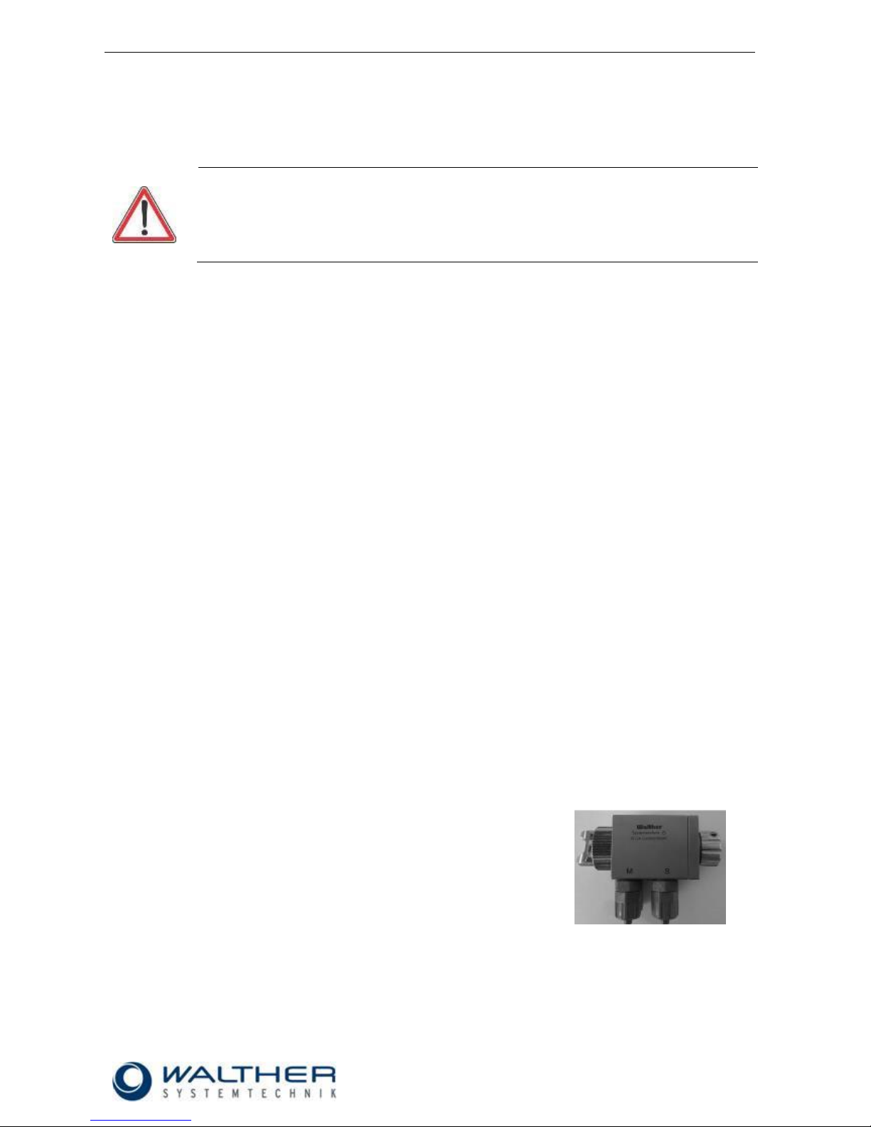
5.1 Hose Mounting
CAUTION
Only use hoses which can be used for the maximum operating pressure of the valve (see
also 4.2 Technical Data).
The three functional hoses will be installed as follows:
Fig.: SMS-11 (Standard)
(In the standard version, the circulation connection is locked; however, it can be easily replaced by a different
connection, if requested).
Material (transparent or white)
Connection M (to pressure container or pump)
Atomizer Air (blue)
Connection Z (to 2/2-way magnetic valve)
Control Air (black)
Connection S (to 3/2-way magnetic valve)
Optional Material Circulation (transparent or white)
Connection M (return into material line)
Optional Jet Width Adjustment (blue)
Connection M5 (to 2/2-way magnetic valve)
Rev. 1.4
Assembly Instructions – Spray Valve SMS-11
Page 9 of 28
Walther Systemtechnik GmbH – D 76726 Germersheim
Telefon: +49 (0)7274-7022-0 Telefax: +49 (0)7274-7022-91
http://www.walther-2000.de – info@walther-2000.de
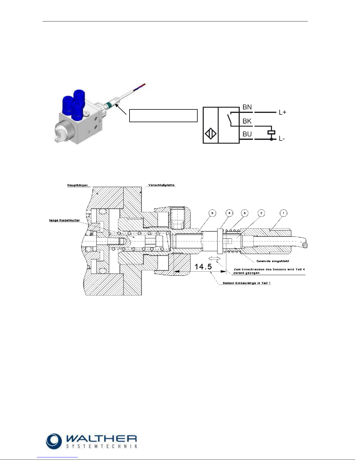
5.1 Raster-Needle Sensor
Optionally, you can use a raster-needle lock with a pre-installed, inductive proximity switch. It will release a
signal when the needle piston with the needle is open. This will help you in digitally monitoring the status
„nozzle open“.
.
Fig.: wiring diagram
5.1.1 Setting of Sensor (Raster-Needle)
1. The screw-in sensor M4 x 0,5 (2) will be glued with a high-strength screw lock into the sensor holder
over a length of 14.5mm (1).
2. Screw in the regulating spindle (5) until the needle is closed and no more material is discharged from
the nozzle.
3. Connect the sensor to a control unit for adjusting.
4. Then slide the spring (3) and the spindle carrier (4) onto the sensor and together screw in into regulating spindle until you receive a signal.
5. Open (unscrew) the regulating spindle until the signal stops (up to max. 8 steps). If the signal of the
sensor hasn’t stopped by then, use the spindle carrier of the sensor for fine-adjustment until the signal stops.
6. The spindle carrier has to be pushed backed against the spring for fine-adjustment so the sensor can
be turned in the regulating spindle until the signal stops.
Raster-needle sensor

Rev. 1.4
Assembly Instructions – Spray Valve SMS-11
Page 10 of 28
Walther Systemtechnik GmbH – D 76726 Germersheim
Telefon: +49 (0)7274-7022-0 Telefax: +49 (0)7274-7022-91
http://www.walther-2000.de – info@walther-2000.de
6 Operation
6.1 General Information
This device may only be operated if the safety-related equipment is permanently effective and not suspended during operation or altered in its intended effectiveness.
6.2 Operation Instructions / Operating Conditions
WARNING
Danger caused by flammable, harmful fluid. Always follow the safety instructions on the container or the safety data sheet for the fluid.
CAUTION
Never point the jet at people. The wearing of eye protection is strongly recommended. The
spraying process can create noise depending on the air and fluid pressures used. Ear protection should be worn, if required.
IMPORTANT
Accident prevention directions will be strictly followed when applying high material
pressures. Please strictly follow the following instructions when planning and constructing
application systems!
The valves of the SMS-11 AUTOMATIC series generally operate with a control air pressure of 3,5 - 6 bar.
Atomized air pressure and material pressure should be closely correlated.
Each spraying valve must be equipped with its own pressure regulator for atomizing air.
In case several spraying valves are supplied by one and the same material pressure tank, these
valves must not spray simultaneously.
The supply route for the material between material pressure tank and spraying valve must not exceed
2000 mm.
If the pause time is a multiple of the spray time, the valve must be sprayed free in a separate location
or the spray valve should be operated several times to optimize the application.
After standstills of 15 min. and more, the valve must be sprayed free by pressing the switch 3 to 5
times.
The atomizing air pressure should be controlled in such a way that it starts before the opening of the needle
and stops after the closing of the nozzle (guarantees broadest maintenance-free operation). The valves can
be controlled for intermittent or continuous use. According to the individual application, the control air must
be adjusted to the operating cycles and to the higher or lower material pressures. 40 tacts per second can be
reached under appropriate operating conditions (material pressure, control air pressure, needle stroke, and
short conductions.
For longer standstills, the material can remain in the valve, if it remains under pressure (no contact to outside
air).

Rev. 1.4
Assembly Instructions – Spray Valve SMS-11
Page 11 of 28
Walther Systemtechnik GmbH – D 76726 Germersheim
Telefon: +49 (0)7274-7022-0 Telefax: +49 (0)7274-7022-91
http://www.walther-2000.de – info@walther-2000.de
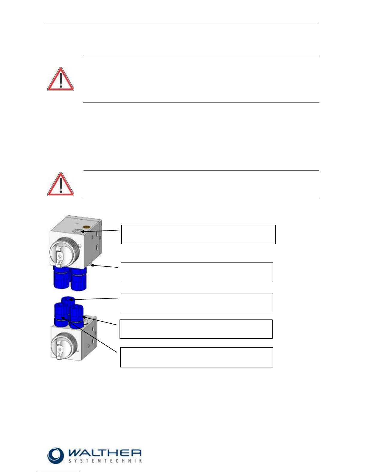
Fig.: Adjusting material quantity through regulating screw (with raster-needle sensor)
IMPORTANT
The quantity of the spray medium can be adjusted to the individual requirements by turning
the adjustment screw.
Right turn: Reducing quantity of the spray medium
Left turn: Increasing quantity of the spray medium
Nozzle and needle can be damaged by wrong handling. Only decrease the material flow (by
a right turn of the regulating knob) if material spills out. Do not turn the regulating knob
further to the right after the nozzle is closed!
6.3 Function – Adjusting the Jet Width
The throttling screw (see also Spare Part Drawing 9.2 Position 12.0 and Spare Part Drawing 9.3 Position 5.0)
is used for adjusting the jet width.
Right turn : reduce the jet width
Left turn : increase the jet width
If the adjustment of the jet width will be remote-controlled (OPTION), the throttling screw (12.0 / 5.0) has to
be completely turned off (right turn). You can then pneumatically adjust the jet width via a pressure regulator
through screw-joint M5 (see also Spare Part Drawing 9.2 Position 15.0 and Spare Part Drawing 9.3 Position
13.0). It works as follows.
Lowering the pressure : reducing the jet width
Increasing the pressure : increasing the jet width
Fig.: Throttling screw and connection (Option) for jet width adjustment
Throttling screw
Regulating screw
Connection M5
for jet width adjustment

Rev. 1.4
Assembly Instructions – Spray Valve SMS-11
Page 12 of 28
Walther Systemtechnik GmbH – D 76726 Germersheim
Telefon: +49 (0)7274-7022-0 Telefax: +49 (0)7274-7022-91
http://www.walther-2000.de – info@walther-2000.de
7 Service, Repair and Malfunction
7.1 General Information
CAUTION
Before starting any maintenance or repair work, ensure that all air-operated tools are
depressurized and disconnected from the air supply.
Before opening the spray valve, it must be disconnected from the air and fluid supply.
Otherwise, ejected components can cause injuries. Wear safety goggles.
The spray valve will be regularly checked for wear and tear. Wear and tear depend upon the
processed material, switching frequency and the conditions of use.
The spray valves of the SMS-11 series are high-quality precision devices which will not fail if treated correctly
and will operate almost maintenance-free. Always keep clean and observe minimum instructions to maintain
a long life of the valve. We recommend lubricating moveable parts regularly and greasing threads, especially
the nozzle threads, when replacing or cleaning the nozzle. Always use clean and filtered material only. The
control air must also be clean and should be slightly oiled, if necessary. Maintenance also depends on the
individual operating conditions and the type of media used.
Particularly when employing the spray valve as color-marking device, the spray cap should be taken off
before a longer standstill. The spray nozzle will be cleaned with a special thinner and a soft cloth. Make sure
that there are no cloth fibers on the nozzle tip.
7.2 Cleaning
Wash equipment thoroughly after use to remove residues and dirt, especially if nozzle needle, needle
sealing or nozzle have to be exchanged (see also 7.4 and 7.5).
IMPORTANT
Only use soft brushes for outside cleaning of the nozzle tips. Never use metal tools with
sharp edges!
During all repair and replacement tasks, take care that the working station as well as the
device for repair will be kept in uttermost cleanliness.
We recommend removing the devices from the machines instead of leaving them installed
during major repair works. (Disconnect the supply lines from pressure!).
7.3 Spare Parts
IMPORTANT
Only use original spare parts from the manufacturer!
Wrong or defective spare parts from other manufacturers can damage the device. If other
than original spare parts of the manufacturer will be used, all obligations from the manufacturer or his sales partners, such as guarantees, service contracts etc. will be forfeited without further notice.

Rev. 1.4
Assembly Instructions – Spray Valve SMS-11
Page 13 of 28
Walther Systemtechnik GmbH – D 76726 Germersheim
Telefon: +49 (0)7274-7022-0 Telefax: +49 (0)7274-7022-91
http://www.walther-2000.de – info@walther-2000.de
7.4 Replacing Nozzle and Nozzle Needle
CAUTION
Remove pressure from all connections and disconnect material and energy supply.
The cover plate is under spring pressure.
Fig.: Standard
Fig.: with raster-needle sensor
1. Disconnect all connections from pressure and turn off energy and material supply!
2. Unfasten retaining ring (1) and remove air cap (2).
3. Unscrew countersunk screws (8) and remove cover plate (7).
(Caution: the cover plate is under spring tension)
4. Make sure that you do not lose the pressure spring (6).
5. Pull out the nozzle needle (5) and unscrew the nozzle (3).
6. Slightly grease the new nozzle needle (5) and slide into main body (4); then remove grease residues
from needle tip.
7. Screw new nozzle (3) into the main body (4).
8. After that screw cover plate (7) onto the main body (4). Make sure that the pressure spring, as described under step 4, is located in the correct position.
9. Then screw the air cap (2) together with the retaining ring (1) onto the main body (4) again.
10. Always perform a functional test after replacing nozzles and needles!
IMPORTANT
Always replace nozzle (3) and nozzle needle (5) at the same time.
Make sure that you thoroughly remove all sediments and material residues from nozzles and
nozzle needles which have already been in use. Material residues in nozzles can cause
leakages in the nozzle-needle-system; and nozzle needles with cured material residues can
damage the sealing elements of the spray valve.
.

Rev. 1.4
Assembly Instructions – Spray Valve SMS-11
Page 14 of 28
Walther Systemtechnik GmbH – D 76726 Germersheim
Telefon: +49 (0)7274-7022-0 Telefax: +49 (0)7274-7022-91
http://www.walther-2000.de – info@walther-2000.de
7.5 Replacing the Sealing Elements
CAUTION
Remove pressure from all connections and disconnect material and energy supply.
The cover plate is under spring pressure.
Fig.1: Standard
Fig.1: with raster-needle sensor
Fig. 1
1. Unscrew cylinder screws (6) and remove cover plate (5). (Caution: the cover plate is under spring
tension)
2. Make sure that the pressure spring (4) does not get lost.
3. Pull out the nozzle needle (3).
4. Unscrew the sealing screw (2) with a socket wrench.
Fig.2: sealing screw
Fig. 2
1. Remove all O-rings (2. 3, 5) and the Variseal (1); mount new O-rings and Variseal and slightly
grease (see Fig. 2).
After replacing the sealing elements, re-assemble in reverse order (see Fig. 1).
IMPORTANT
Gaskets and seal seats can be damaged. Do not use any sharp-edged metal tools or objects
when removing and inserting the gaskets!

Rev. 1.4
Assembly Instructions – Spray Valve SMS-11
Page 15 of 28
Walther Systemtechnik GmbH – D 76726 Germersheim
Telefon: +49 (0)7274-7022-0 Telefax: +49 (0)7274-7022-91
http://www.walther-2000.de – info@walther-2000.de
7.6 Troubleshooting
7.7 General Information
IMPORTANT
First check all supply lines for connection and serviceability.
In case of serious problems that cannot be resolved, please contact the Walther Systemtechnik GmbH
customer service.
7.8 Customer Service / Support
Walther Systemtechnik GmbH
Hockenheimer Straße 3
D-76726 Germersheim
Germany
Phone ++49(0)7274-7022-0
Fax ++49(0)7274-7022-91
Email info@walther-2000.de
Internet www.walther-2000.de
7.9 Malfunctions
Error
Possible Cause
Action
Nozzle needle does
not open
Not enough control air supplied
Check if enough control air available (3 6 bar).
Leakages
Check if O-Ring (7.5) is defective.
Needle is sticky within the needle sealing
Disassemble and clean.
Needle stroke is set too low.
Check if needle stroke is correctly set.
No atomizer air
Atomizer air pressure set too low
Check if sufficient atomizer air (see also
Technical Data 4.2) is applied to the
spray valve
No material
discharged
Nozzle is clogged by material
Clean nozzle and needle (see also 7.4).
Material pressure is set too low
Check if sufficient material pressure
(see also 4.2 Technical Data) is applied
to the spray valve
Spray image not
correct
Air cap is dirty
Clean air cap
Wrong air ratio
See chapter 7.10

Rev. 1.4
Assembly Instructions – Spray Valve SMS-11
Page 16 of 28
Walther Systemtechnik GmbH – D 76726 Germersheim
Telefon: +49 (0)7274-7022-0 Telefax: +49 (0)7274-7022-91
http://www.walther-2000.de – info@walther-2000.de
7.10 Spray Images / Types of Defects
SPRAY IMAGE
PROBLEM
CAUSE
ACTION
Normal Spray Image (Flat jet)
Normal Spray Image (Round jet)
Spray image shaped
too much
upwards and
downwards
Spray image shaped
too much
upwards and
downwards
Spray image shaped
too much
upwards and
downwards
Spray image too much
left-sided or right-sided
Spray image too much
left-sided or right-sided
Spray image too much
left-sided or right-sided
Heavy application in the
middle of the spray image
Heavy application in the
middle of the spray
image
Heavy application in the
middle of the spray
image
Split
spray image
Split
spray image
Split
spray image

Rev. 1.4
Assembly Instructions – Spray Valve SMS-11
Page 17 of 28
Walther Systemtechnik GmbH – D 76726 Germersheim
Telefon: +49 (0)7274-7022-0 Telefax: +49 (0)7274-7022-91
http://www.walther-2000.de – info@walther-2000.de
8 Taking out of Service
CAUTION
Remove pressure from all connections and disconnect supply of energy and material.
Follow the operating and maintenance instructions!
Danger of accidents and hazard for environment. Do not spill medium. Medium will be
properly disposed of (hazardous waste).
8.1 Short Interruption
A short interruption (15 min or more) has to be followed by a clean spraying.
8.2 Long-term Interruption
The following has to be observed for a long-term interruption of the device/machine:
Remove pressure from supply lines.
Loosen retaining ring (1) and remove air cap (2).
Unscrew nozzle (3) and clean with a special thinner and a soft cloth. Make sure that not fibers remain
on the nozzle tip.
8.3 Shutdown of Device
The following is important for a shutdown of the machine / device:
Remove pressure from supply lines and disconnect.
Clean spray valve with a special thinner.
Properly dispose of the medium.
8.4 Disposal
CAUTION
Any disposal of the device will be performed in accordance with the guiding rules and
regulations on waste disposal of the local authorities. Lubricants are considered hazardous
waste!

Rev. 1.4
Assembly Instructions – Spray Valve SMS-11
Page 18 of 28
Walther Systemtechnik GmbH – D 76726 Germersheim
Telefon: +49 (0)7274-7022-0 Telefax: +49 (0)7274-7022-91
http://www.walther-2000.de – info@walther-2000.de
9 Appendix
9.1 Dimensioned Drawing of SMS-11 (Standard and with Raster-Needle Sensor)

Rev. 1.4
Assembly Instructions – Spray Valve SMS-11
Page 19 of 28
Walther Systemtechnik GmbH – D 76726 Germersheim
Telefon: +49 (0)7274-7022-0 Telefax: +49 (0)7274-7022-91
http://www.walther-2000.de – info@walther-2000.de
9.1.1 Dimensioned Drawing of SMS-11 with Clamping Holder (Standard)
The clamping holder is an easy way of fastening the spray valve (e.g. on a shaft). The clamp holder will be
attached to the spray valve with two screws.
9.1.2 Dimensioned Drawing of SMS-11 with Quick-Change Board (Standard)
A quick-change board (with supply line for air material supply) was designed for a fast mounting/dismounting
of the valve. The board/adapter comes with a locking device and a banjo screw for attaching the spray valve.

Rev. 1.4
Assembly Instructions – Spray Valve SMS-11
Page 20 of 28
Walther Systemtechnik GmbH – D 76726 Germersheim
Telefon: +49 (0)7274-7022-0 Telefax: +49 (0)7274-7022-91
http://www.walther-2000.de – info@walther-2000.de
9.2 Spare Part Drawing for SMS-11 (Standard)

Rev. 1.4
Assembly Instructions – Spray Valve SMS-11
Page 21 of 28
Walther Systemtechnik GmbH – D 76726 Germersheim
Telefon: +49 (0)7274-7022-0 Telefax: +49 (0)7274-7022-91
http://www.walther-2000.de – info@walther-2000.de
9.2.1 Spare Part List for SMS-11 (Standard)
Fig.-No.
Article-No.
Qty
Description
1.0
97410028
1
Collar ring
2.0 * 1
Air cap, flat-spray, ø 20 x 14.5mm
2.1 * 1
Air cap, round-spray, ø 20 x 11mm
3.0 * 1
Nozzle, stainless steel, ø 12 x 18mm
4.0
97510345
1
Main body SMS-11, stainless steel, complete
5.0
97810054
1
Sealing sleeve, complete
5.1
97640155
1
Variseal
5.2
97640317
1
O-Ring / Viton®
5.3
97810053
1
Sealing sleeve
5.4
97640316
2
O-Ring / Viton®
5.5
97640026
1
O-Ring / Viton®
6.0 * 1
Nozzle needle, complete
6.1
97640007
1
O-Ring / Viton®
7.0
97820076
1
Pressure spring
8.0
97320318
1
Raster screw
9.0
97511021
1
Cover plate, complete
9.1
97511020
1
Cover plate 30 x 30 x 10mm
9.2
97610017
2
Threaded pin DIN 913
9.3
97820077
2
Pressure spring
9.4
97650004
2
Ball, stainless steel
10.0
97610055
2
Countersunk screw DIN 7991
11.0
97320668
1
Regulating knob, stainless steel, complete
11.1
97610034
1
Threaded pin DIN 915
12.0
97380032
1
Throttling screw, complete
12.1
97380033
1
Throttling screw
12.2
97640364
1
O-Ring / Viton®
13.0
97220300
1
Locking screw, stainless steel 1/8"
14.0
97610249
1
Threaded pin DIN 915
15.0
97610339
1
Screw joint M5, complete, with sealing
16.0
97220022
3
Straight screw-in screw joint 1/8" - 6/4 KU
* Article numbers can be found on the following pages.
IMPORTANT
Always indicate the inscribed serial numbers when ordering spare parts!

Rev. 1.4
Assembly Instructions – Spray Valve SMS-11
Page 22 of 28
Walther Systemtechnik GmbH – D 76726 Germersheim
Telefon: +49 (0)7274-7022-0 Telefax: +49 (0)7274-7022-91
http://www.walther-2000.de – info@walther-2000.de
9.3 Spare Part List for SMS-11 (Raster-Needle Sensor)

Rev. 1.4
Assembly Instructions – Spray Valve SMS-11
Page 23 of 28
Walther Systemtechnik GmbH – D 76726 Germersheim
Telefon: +49 (0)7274-7022-0 Telefax: +49 (0)7274-7022-91
http://www.walther-2000.de – info@walther-2000.de
9.3.1 Spare Part List for SMS-11 (Raster-Needle Sensor)
Fig.-No.
Article No.
Qty
Description
1.0
97410028
1
Collar ring
2.0 * 1
Air cap, flat-spray, diam. 20 x 14.5mm
2.1 * 1
Air cap, round-jet, diam. 20 x 11mm
3.0 * 1
Nozzle, stainless steel, diam. 12 x 18mm
4.0
97510345
1
Main body SMS-11, stainless steel, complete
5.0
97380032
1
Throttling screw, complete
5.1
97640364
1
O-ring / Viton®
5.2
97380033
1
Throttling screw
6.0
97810054
1
Retainer, complete
6.1
97640155
1
Variseal
6.2
97640317
1
O-ring / Viton®
6.3
97640316
2
O-ring / Viton®
6.4
97810053
1
Retainer
6.5
97640026
1
O-ring / Viton®
7.0 * 1
Nozzle needle, complete
7.1
97640007
1
O-ring / Viton®
8.0
97820076
1
Pressure spring
9.0
97511494
1
Cover plate, complete
9.1
97320923
1
Sensor spindle, complete
9.1.1
97320820
1
Raster screw, diam. 13 x 23.5mm, stainless steel
9.1.2
97320317
1
Regulating spindle carrier, st.steel, 7 x 7.5mm
9.1.3
97820074
1
Pressure spring 0.60 x 6.70mm
9.1.4
97320670
1
Sensor holder, st.steel, 7 x 18mm, complete
9.2
97511020
1
Cover plate, 30 x 30 x 10.5mm
9.3
97650004
2
Ball, stainless steel
9.4
97820077
2
Pressure spring
9.5
97610017
2
Threaded pin DIN 913
9.6
97320821
1
Regulating knob, diam. 19 x 10mm, stainless steel
9.7
97610034
1
Threaded pin DIN 915
10.0
97610055
2
Countersunk screw DIN 7991
11.0
97610249
1
Threaded pin DIN 915
12.0
97220300
1
Locking screw, stainless steel, 1/8"
13.0
97610339
1
Locking screw M5, complete with sealing
14.0
97220022
3
Straight screw-in screw joint 1/8" - 6/4 KU
* Article numbers are indicated on the following pages.
IMPORTANT
Always indicate the inscribed serial numbers when ordering spare parts!
9.4 Wear-and-Tear Parts
Wear-and-Tear Parts Kit complete for SMS-11 (Standard)1
Article-No.
Description
97640319
Wear Parts Kit for SMS-11, VITON
1
We recommend this wear-and-tear kit when exchanging nozzle needles and nozzle.

Rev. 1.4
Assembly Instructions – Spray Valve SMS-11
Page 24 of 28
Walther Systemtechnik GmbH – D 76726 Germersheim
Telefon: +49 (0)7274-7022-0 Telefax: +49 (0)7274-7022-91
http://www.walther-2000.de – info@walther-2000.de
9.5 Article Numbers for Air Caps
2.0
Air cap, Flat-jet, Standard, 60° (Ø20x14.5mm)
Article-No.
Description
97310234
Air cap, Flat-jet, 0.2-1.0mm
97310235
Air cap, Flat-jet, 1.2-1.5mm
97310236
Air cap, Flat-jet, 1.8-2.0mm
97310237
Air cap, Flat-jet, 2.5mm
2.0
Air cap, Flat-jet, Standard, 90° (Ø20x14.5mm)
Article-No.
Description
97310238
Air cap, Flat-jet, 0.2-1.0mm
97310239
Air cap, Flat-jet, 1.2-1.5mm
97310240
Air cap, Flat-jet, 1.8-2.0mm
97310241
Air cap, Flat-jet, 2.5mm
2.0
Air cap, Flat-jet, KLS, 60° (Ø20x14.5mm)
Article-No.
Description
97310242
Air cap, Flat-jet, KLS 0.2-1.0mm
97310243
Air cap, Flat-jet, KLS 1.2-1.5mm
97310244
Air cap, Flat-jet, KLS 1.8-2.0mm
97310245
Air cap, Flat-jet, KLS 2.5mm
2.0
Air cap, Flat-jet, KLS, 90° (Ø20x14.5mm)
Article-No.
Description
97310246
Air cap, Flat-jet, KLS 0.2-1.0mm
97310247
Air cap, Flat-jet, KLS 1.2-1.5mm
97310248
Air cap, Flat-jet, KLS 1.8-2.0mm
97310249
Air cap, Flat-jet, KLS 2.5mm
2.1
Air cap, Round-jet, Standard, 15° (Ø20x11mm)
Article-No.
Description
97310034
Air cap, Round-jet, 0.2-1.0mm
97310035
Air cap, Round-jet, 1.2mm-1.5mm
97310080
Air cap, Round-jet, 1.8-2.0mm
97310091
Air cap, Round-jet, 2.5mm
2.1
Air cap, Round-jet, KLS, 15° (Ø20x11mm)
Article-No.
Description
97310084
Air cap, Round-jet, KLS 0.2-1.0mm
97310085
Air cap, Round-jet, KLS 1.2-1.5mm
97310086
Air cap, Round-jet, KLS 1.8-2.0mm
97310250
Air cap, Round-jet, KLS 2.5mm

Rev. 1.4
Assembly Instructions – Spray Valve SMS-11
Page 25 of 28
Walther Systemtechnik GmbH – D 76726 Germersheim
Telefon: +49 (0)7274-7022-0 Telefax: +49 (0)7274-7022-91
http://www.walther-2000.de – info@walther-2000.de
2.1
Marking Air cap, Round jet 8° (Ø20x18mm)
Article-No.
Description
97310578
Marking air cap, 0.2-0.5mm
97310727
Marking air cap, 0.8-1.0mm
2.1
Special spin air cap, round jet
Article No.
Description
97310197
Special spin 0.2-2.0mm
9.6 Article Numbers for Nozzles
3.0
Nozzle, Standard, stainless steel (Ø12x18mm)
Article-No.
Description
97210110
Nozzle, Standard, 0.2mm
97210111
Nozzle, Standard, 0.3mm
97210112
Nozzle, Standard, 0.5mm
97210113
Nozzle, Standard, 0.8mm
97210114
Nozzle, Standard, 1.0mm
97210115
Nozzle, Standard, 1.2mm
97210116
Nozzle, Standard, 1.5mm
97210117
Nozzle, Standard, 2.0mm
97210118
Nozzle, Standard, 2.5mm
3.0
Nozzle, KLS, stainless steel (Ø12x17.2mm)
Article-No.
Description
97210119
Nozzle, KLS, 0.2mm
97210120
Nozzle, KLS, 0.3mm
97210121
Nozzle, KLS, 0.5mm
97210122
Nozzle, KLS, 0.8mm
97210123
Nozzle, KLS, 1.0mm
97210124
Nozzle, KLS, 1.2mm
97210125
Nozzle, KLS, 1.5mm
97210126
Nozzle, KLS, 2.0mm
97210564
Nozzle, KLS, 2.5mm
3.0
Marking nozzle, stainless steel 8°(Ø8x18mm)
Article-No.
Description
97212055
Marking nozzle 0.2mm
97211875
Marking nozzle 0.3mm
97212025
Marking nozzle 0.4mm
97211461
Marking nozzle 0.5mm
97212146
Marking nozzle 0.8mm

Rev. 1.4
Assembly Instructions – Spray Valve SMS-11
Page 26 of 28
Walther Systemtechnik GmbH – D 76726 Germersheim
Telefon: +49 (0)7274-7022-0 Telefax: +49 (0)7274-7022-91
http://www.walther-2000.de – info@walther-2000.de
3.0
Nozzle, special spin, stainless steel (Ø12x18mm)
Article No.
Description
97210483
Nozzle, special spin, 0.2mm
97210484
Nozzle, special spin, 0.3mm
97210482
Nozzle, special spin, 0.5mm
97210485
Nozzle, special spin, 0.8mm
97211030
Nozzle, special spin, 1.0mm
97212510
Nozzle, special spin, 1.5mm
97212397
Nozzle, special spin, 2.0mm
9.7 Article Numbers for Nozzle Needles
9.0
Nozzle needle complete, standard and marking,
Special spin, VITON
Article-No.
Description
97110884
Nozzle needle, Standard, 0.2/0.3mm
97110885
Nozzle needle, Standard, 0.5mm
97110886
Nozzle needle, Standard, 0.8mm
97110887
Nozzle needle, Standard, 1.0mm
97110888
Nozzle needle, Standard, 1.2mm
97110889
Nozzle needle, Standard, 1.5mm
97110890
Nozzle needle, Standard, 2.0mm
97110891
Nozzle needle, Standard, 2.5mm
9.0
Nozzle needle complete, KLS, VITON
Article-No.
Description
97110900
Nozzle needle, KLS, 0.2/0.3mm
97110901
Nozzle needle, KLS, 0.5mm
97110902
Nozzle needle, KLS, 0.8mm
97110903
Nozzle needle, KLS, 1.0mm
97110904
Nozzle needle, KLS, 1.2mm
97110905
Nozzle needle, KLS, 1.5mm
97110906
Nozzle needle, KLS, 2.0mm
97110907
Nozzle needle, KLS, 2.5mm
9.8 Screw Joints
6.0
Straight screwed joint for material and air
Article-No.
Description
97220022
Straight screwed joint with nut SW 13x28mm /1/8-6/4 (Standard)
97220243
Straight screwed joint with nut SW 13x28mm /1/8-8/6

Rev. 1.4
Assembly Instructions – Spray Valve SMS-11
Page 27 of 28
Walther Systemtechnik GmbH – D 76726 Germersheim
Telefon: +49 (0)7274-7022-0 Telefax: +49 (0)7274-7022-91
http://www.walther-2000.de – info@walther-2000.de
9.9 Accessories
Figure
Article Number
Description
97xxxxxx
Nozzle extension
(see Product Catalog ACCESSORIES)
97410042
Retainer/collar ring hexagonal
97410059
Retainer ring stainless steel
97910015
Clamp mounting
(see 9.1.1)
97910186
Quick change board/Adapter
(see 9.1.2)
979565.004
Heating plate
(see Product Catalog ACCESSORIES)
979444
Cleaning set
(see also Product catalog ACCESSORIES)
97320602
Centering sleeve for an exact positioning of the valve

Rev. 1.4
Assembly Instructions – Spray Valve SMS-11
Page 28 of 28
Walther Systemtechnik GmbH – D 76726 Germersheim
Telefon: +49 (0)7274-7022-0 Telefax: +49 (0)7274-7022-91
http://www.walther-2000.de – info@walther-2000.de
9.9.1 Center Hole for Centering Sleeve 97320602
Important!
If a centering sleeve is retrofitted to an existing valve, the valve must be returned to us for
retrofitting of center hole.
 Loading...