

Rev. 1.4
Assembly Instructions - Micro Point Pulse Valve MPP-SPEED
Page 1 of 17
Walther Systemtechnik GmbH – D 76726 Germersheim
Telefon: +49 (0)7274-7022-0 Telefax: +49 (0)7274-7022-91
http://www.walther-2000.de – info@walther-2000.de
NOTE
Please read the Assembly Instructions carefully before first using the incomplete device and
strictly adhere to the instructions!
The incomplete device may only be worked with and worked on by persons who are familiar
with the assembly instructions and the current regulations for industrial safety and accident
prevention.
Assembly Instructions
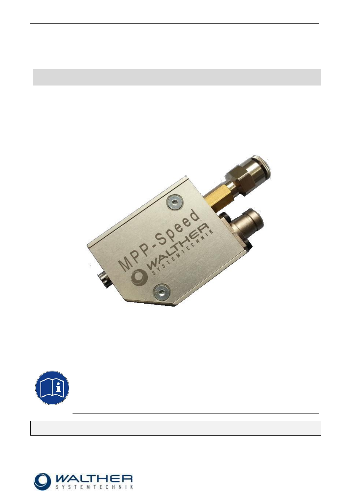
Micro Point Pulse Valve MPP-Speed
Article number: MPP-SPEED
Pic.: MPP- Speed with medium connector (high-pressure hose)
Always keep a translated version of the original Assembly Instructions at the incomplete device!
The assembly instructions have to be close at hand any time!

Rev. 1.4
Assembly Instructions - Micro Point Pulse Valve MPP-SPEED
Page 2 of 17
Walther Systemtechnik GmbH – D 76726 Germersheim
Telefon: +49 (0)7274-7022-0 Telefax: +49 (0)7274-7022-91
http://www.walther-2000.de – info@walther-2000.de
Table of Contents
Page
EC DECLARATION OF INCORPORATION ....................................................................................................................... 3
1 INTRODUCTION ................................................................................................................................................. 4
1.1 TARGET GROUP OF THE ASSEMBLY INSTRUCTIONS ............................................................................................................. 4
1.2 LIST OF SIGNS AND SYMBOLS ........................................................................................................................................ 4
2 SAFETY............................................................................................................................................................... 4
2.1 GENERAL INFORMATION ............................................................................................................................................. 4
2.2 DANGERS FROM RESIDUAL ENERGY ............................................................................................................................... 4
2.3 WARRANTY .............................................................................................................................................................. 4
2.4 CORRECT USE ........................................................................................................................................................... 5
2.5 INCORRECT USE ........................................................................................................................................................ 5
2.6 QUALIFICATION OF PERSONNEL .................................................................................................................................... 5
3 TRANSPORT ....................................................................................................................................................... 6
3.1 PACKAGING .............................................................................................................................................................. 6
3.2 TASKS BEFORE TRANSPORT .......................................................................................................................................... 6
4 FUNCTIONAL DESCRIPTION ............................................................................................................................... 6
4.1 FUNCTIONAL PRINCIPLE .............................................................................................................................................. 6
4.2 TECHNICAL DATA OF INCOMPLETE DEVICE ...................................................................................................................... 7
4.3 STRESS TEST ............................................................................................................................................................. 7
4.4 TYPE LABEL .............................................................................................................................................................. 8
5 INSTALLATION AND INITIAL START-UP ................................................................................................................ 8
5.1 HOSE CONNECTION ................................................................................................................................................... 8
5.2 INTERFACES .............................................................................................................................................................. 8
5.3 ELECTRICAL INTERFACES .............................................................................................................................................. 9
6 OPERATION ....................................................................................................................................................... 9
6.1 GENERAL INFORMATION ............................................................................................................................................. 9
6.2 OPERATING INSTRUCTIONS / OPERATIONAL REQUIREMENTS .............................................................................................. 9
6.3 ELECTRICAL CONTROLS ............................................................................................................................................. 10
7 TAKING OUT OF OPERATION ............................................................................................................................ 11
7.1 SHORT INTERRUPTION .............................................................................................................................................. 11
7.2 LONG-TERM INTERRUPTION ....................................................................................................................................... 11
7.3 FINAL SHUTDOWN OF SYSTEM / DEVICE ...................................................................................................................... 11
8 MAINTENANCE AND REPAIR ............................................................................................................................ 11
8.1 GENERAL ............................................................................................................................................................... 11
8.2 CLEANING .............................................................................................................................................................. 12
8.3 REPLACING NOZZLE ................................................................................................................................................. 12
8.4 CUSTOMER SERVICE / SUPPORT .................................................................................................................................. 13
9 TROUBLESHOOTING ........................................................................................................................................ 13
9.1 GENERAL INFORMATION ............................................................................................................................................ 13
10 APPENDIX ........................................................................................................................................................ 14
10.1 TECHNICAL DRAWING .......................................................................................................................................... 14
10.1.1 Spare Parts Drawing ............................................................................................................................. 15
10.1.2 Spare Parts List ..................................................................................................................................... 15
10.2 POSSIBLE VERSIONS ............................................................................................................................................ 16
10.3 ACCESSORIES ..................................................................................................................................................... 16
10.3.1 WALTHER-Light barrier (WLS) ............................................................................................................... 17

Rev. 1.4
Assembly Instructions - Micro Point Pulse Valve MPP-SPEED
Page 3 of 17
Walther Systemtechnik GmbH – D 76726 Germersheim
Telefon: +49 (0)7274-7022-0 Telefax: +49 (0)7274-7022-91
http://www.walther-2000.de – info@walther-2000.de
EC Declaration of Incorporation
in accordance with EU Machinery Directive 2006/42/EU, dated 17 May 2006, Appendix II B
We herewith confirm that the below mentioned incomplete device meets the basic requirements for safety
and health as stated in EU Machinery Directive 2006/42/EU for its design and construction as well as for the
configuration released by us on the market. This machine component will not be operated before it has been
determined that the incomplete system where the machine component will be installed also meets the
requirements of the Directive (2006/42/EG).
Manufacturer
Walther Systemtechnik GmbH
Hockenheimer Straße 3
D- 76726 Germersheim
Description
Micro Point Pulse Valve MPP-Speed, article-No. MPP-SPEED
We also declare the conformity with other, product-relevant directives/guidelines:
Mach. Direct. 2006/42/EU App. I, Clause: 1.1.2, 1.1.3, 1.1.5, 1.1.6, 1.3.2, 1.3.3,
1.3.4, 1.5.1, 1.5.8, 1.5.9
EMC- Directive 2014/30/EU, dated 26. February 2014
Applied harmonized standards, in particular:
DIN EN ISO 12100 Safety of Machinery – General Design Principles –
Risk Assessment and Risk Reduction (ISO
12100:2010)
In addition, we also confirm that the special documentation according to Appendix VII Part B has
been prepared.
The manufacturer, respectively his authorized representative obligates himself to submit this documentation
to the market surveillance authorities, if requested.
This EC Declaration of Incorporation becomes invalid if the incomplete device will be altered or changed
without consent of Walther Systemtechnik GmbH.
Authorized representative for Technical Documentation:
Stefan Hirl, Hockenheimer Straße 3, D- 76726 Germersheim
Germersheim, 22 December 2018
(Place, Date) (Stefan Hirl, Management)
Rev. 1.4
Assembly Instructions - Micro Point Pulse Valve MPP-SPEED
Page 4 of 17
Walther Systemtechnik GmbH – D 76726 Germersheim
Telefon: +49 (0)7274-7022-0 Telefax: +49 (0)7274-7022-91
http://www.walther-2000.de – info@walther-2000.de
DANGER
Describes a potentially dangerous situation.
Death, grievous bodily harm or severe material damage WILL occur if the respective
measures of precaution have not been taken
WARNING
Describes a potentially dangerous situation.
Death, grievous bodily harm or severe material damage MAY occur if the respective
measures of precaution have not been taken
CAUTION
Describes a potentially dangerous situation.
Slight injuries CAN occur if the respective measures of precaution have not been
taken. This signal word is also used to describe possible property damages.
IMPORTANT
Indicates tips for usage and other particularly useful information.
No dangerous situation.
1 Introduction
1.1 Target group of the Assembly Instructions
Operating personal
Maintenance personal
1.2 List of signs and symbols
The assembly instructions warn users of operations which may put their health at risk. The warnings are
indicated by combinations of text and symbols as follows:
2 Safety
2.1 General Information
The construction of this device is according to the latest technology and is absolutely reliable. The individual
components as well as the complete device are continuously checked by our quality management.
2.2 Dangers from Residual Energy
Please note that there are residual energies from mechanical, hydraulic, pneumatic and electric/electronic
sources at the machine, and take appropriate measures when training the operating personnel.
2.3 Warranty
According to the conditions laid down by the German Engineering Federation (VDMA), Walther Systemtechnik GmbH has a guarantee of 12 months under normal European operating conditions on its own parts
(spare parts are excluded); or according to the conditions of the manufacturer.
This guarantee can only be granted by Walther Systemtechnik GmbH, if:
the user has thorough knowledge of the content of the assembly instructions;
the user follows the instructions and notes contained in the assembly instructions;
the user does not rebuild or make changes on parts of the device without prior consent of WST Sys-
temtechnik GmbH.
Rev. 1.4
Assembly Instructions - Micro Point Pulse Valve MPP-SPEED
Page 5 of 17
Walther Systemtechnik GmbH – D 76726 Germersheim
Telefon: +49 (0)7274-7022-0 Telefax: +49 (0)7274-7022-91
http://www.walther-2000.de – info@walther-2000.de
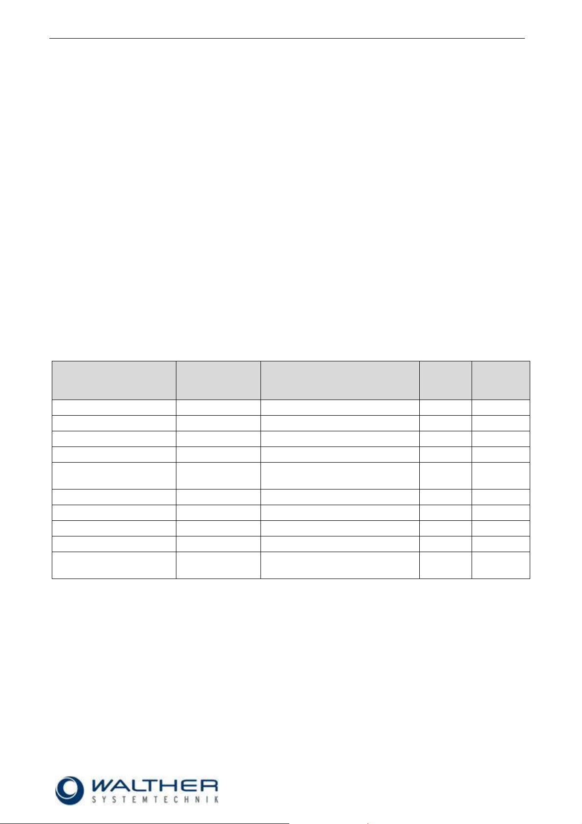
Personnel
Task
Trained
Personnel
Personnel with technical
qualification
Specialist
Supervisor
Packaging, Transport
X
-
-
-
Commissioning
X
X
-
Operation
X
-
Troubleshooting, general
X
X
-
Troubleshooting,
mechanical
-
X
-
-
Troubleshooting, electrical
-
-
X
-
Setting up
-
X
-
-
Maintenance
-
X
-
-
Repair
-
X
X
-
Taking out of service,
Storage
-
X
X
-
2.4 Correct Use
This device is a needle valve suitable for the processing of sprayable media in continuous as well as intermittent use. It is not suitable for spraying aggressive fluids such as acids, alkaline solutions, cleaning agents,
chemicals, etc. In case of doubt, please contact the manufacturer.
2.5 Incorrect Use
Operating the device with insufficient knowledge about the operation, maintenance and care of the
device.
Making changes, extensions or alterations on the device that may hamper its safety without the prior
consent of Walther Systemtechnik GmbH.
Operating the device with defective safety installations or not properly attached or malfunctioning
safety devices.
Using unsuitable materials.
Handling the device while energized.
2.6 Qualification of Personnel
Only trained and instructed personnel may conduct work on the equipment.
The responsibilities of the personnel for assembly work, operation, repair work or maintenance work must be
clearly assigned to individuals!
Persons in training may work with the equipment under supervision of an experienced person only.
Rev. 1.4
Assembly Instructions - Micro Point Pulse Valve MPP-SPEED
Page 6 of 17
Walther Systemtechnik GmbH – D 76726 Germersheim
Telefon: +49 (0)7274-7022-0 Telefax: +49 (0)7274-7022-91
http://www.walther-2000.de – info@walther-2000.de
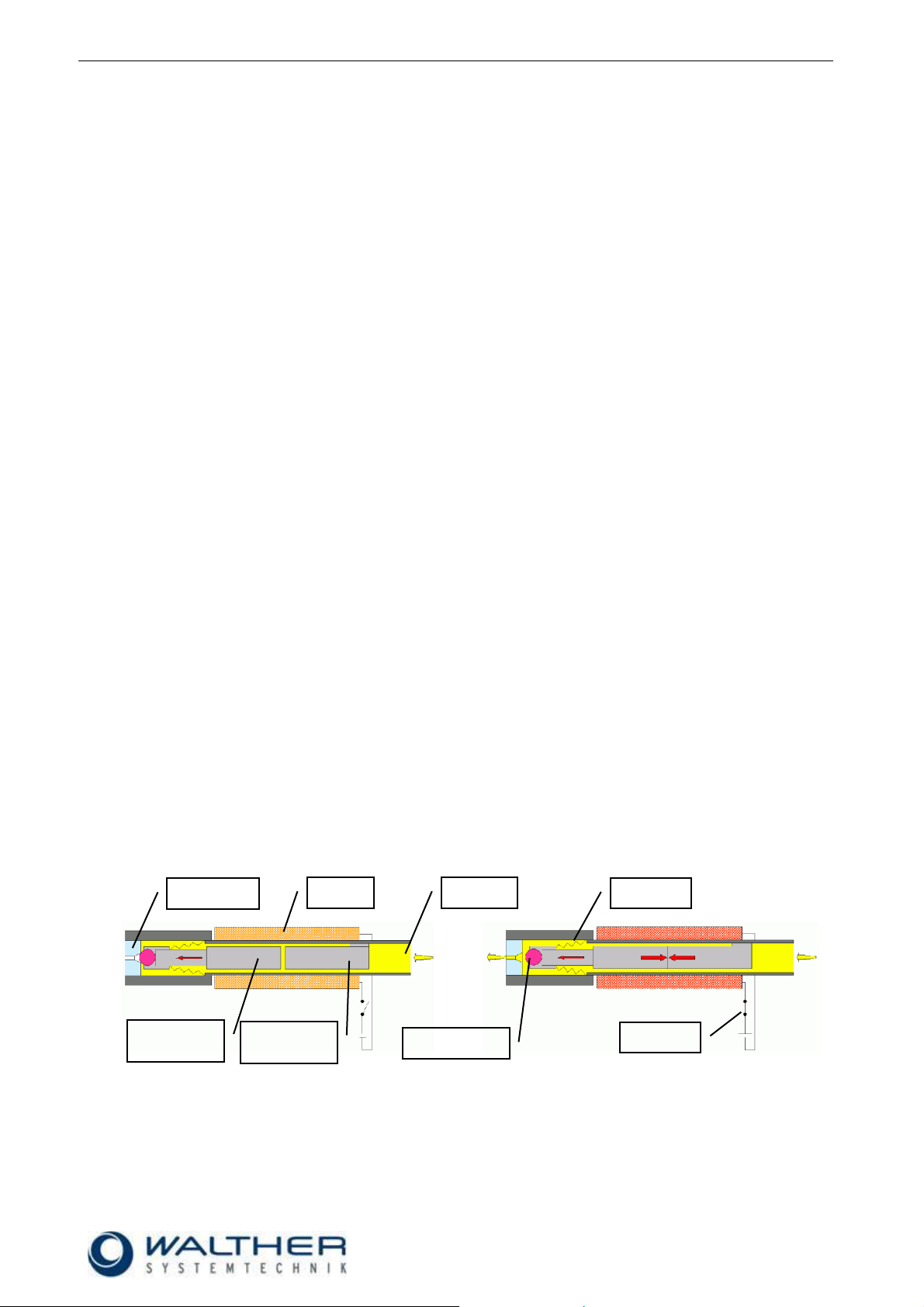
Coil without current (valve closed)
Coil with current (valve open)
Medium
Switch
Coil
Mobile
anchor
Spring
Valve seat
Stationary
anchor
Valve ball
3 Transport
3.1 Packaging
The type of packaging will be selected according to the mode of transport. If not separately negotiated, the
packaging will be made in accordance with the packaging directive of company Walther Systemtechnik
GmbH. This directive complies with HPE Packaging Regulations.
3.2 Tasks before Transport
The following tasks have to be fulfilled before the actual transport.
Disconnect energy supply lines
Extreme care has to be applied when transporting the incomplete machine and its individual parts in order to
avoid damages from external impacts or careless on- and off-loading. Depending on type and duration of
transport, appropriate transport securing devices have to be used. The incomplete device itself will be adjusted and leveled by appropriate fastening elements.
4 Functional Description
The MPP-Speed Micro Point Pulse Valve is an incomplete, electrically controlled application device designed for the application of materials such as greases, paints, oils, etc. If the power supply is cut off or fails,
the spring closes the needle. The medium is transported to the valve either out of a pressure tank or a pump.
4.1 Functional Principle
By using hard materials it is possible to achieve little opening strokes of only a few hundredths of a millimeter
in size. Also, an extremely high repeatability in the range of thousandths millimeters can be realized.
The MPP-Speed is electromagnetically operated. The medium flows around the nozzle sphere. The closing
spring acts on the mobile anchor with a valve ball. When there is a current feed through the valve coil, the
mobile anchor with the valve ball is magnetically pulled by the magnetic field of the stationary anchor. The
micro valve opens and the medium emerges. After pulsing, the nozzle is closed again by the closing spring.

Rev. 1.4
Assembly Instructions - Micro Point Pulse Valve MPP-SPEED
Page 7 of 17
Walther Systemtechnik GmbH – D 76726 Germersheim
Telefon: +49 (0)7274-7022-0 Telefax: +49 (0)7274-7022-91
http://www.walther-2000.de – info@walther-2000.de
4.2 Technical Data of Incomplete Device
Dimensions (length x width x height) [mm]
39 x 20 x 75,5
Weight [g]
approx. 87g
Pressure range [bar]
up to 50
Viscosity range [mPa.s]
1-1000 / optional / heated: higher depending on medium
Valve stroke [mm]
0,1(Standard) 0,03/0,06/0,15
Life expectancy
up to 500 mio. cycles
Max. allowed coil temperature [°C]
90
Max. dosing frequency [Hz]
up to 400
Min. control time [µs]
400
Repetition accuracy [CV]
< 5%
Minimal grid width [mm]
6
Dosable media
greases, oils, paint, UV glue / others upon request
Voltage [VDC]
24
Power consumption heating [W]
14,4
Current consumption heating [mA]
600
Nominal current [A]
1
Holding current [mA]
100-200
Coil resistance [Ohm]
6
Coil inductance [mH] (valve coil mounted on
MPP)
0,8
Electrical connection
Soldering pins/300mm strand, tin-coated or with plug 2poles Molex Type 70066-176
Recommended peak current [VDC]
24 during 400 µs (current limitation required for higher voltages)
Recommended hold current
0,2-0,3A / 1,2-2 VDC no time limit
Hold-Voltage
Peak-Time 500µs
Peak-Time 800µs
Peak-Time 1000µs
10%
15%
20%
25%
30%
40%
50%
60%
70%
80%
85%
90%
95%
General Data
Energy supply
4.3 Stress Test
Parameters:
- Shot Number: 3000
- Duration: 167sek.
- Temperature: 90°

Rev. 1.4
Assembly Instructions - Micro Point Pulse Valve MPP-SPEED
Page 8 of 17
Walther Systemtechnik GmbH – D 76726 Germersheim
Telefon: +49 (0)7274-7022-0 Telefax: +49 (0)7274-7022-91
http://www.walther-2000.de – info@walther-2000.de
The connection for the material will be determined with the actual order (screw connection can be ordered separately as accessories)
Connection for material hose
Connection for material hose
Connection for electronic
plug
Fastening thread (see
technical drawing)
4.4 Type Label
The type designation has been lasered near the material connection. Also the serial number has been
marked in this area.
5 Installation and Initial Start-up
The valves can be installed in any position. The distance to the surface to be applied with the medium
depends on the spray pattern.
Vibrations of the valve caused by fast intermitting cycles require solid and tight installation. Machine vibrations to the valves should be avoided.
5.1 Hose Connection
The material hose will be connected as follows:
5.2 Interfaces

Rev. 1.4
Assembly Instructions - Micro Point Pulse Valve MPP-SPEED
Page 9 of 17
Walther Systemtechnik GmbH – D 76726 Germersheim
Telefon: +49 (0)7274-7022-0 Telefax: +49 (0)7274-7022-91
http://www.walther-2000.de – info@walther-2000.de
5.3 Electrical Interfaces
CAUTION
Do not point the jet at people. The wearing of eye protection is strongly recommended.
The valve must not be operated without a nozzle – it could be destroyed!
WARNING
Danger caused by flammable, harmful fluid. Always follow the safety instructions on the
container or the safety data sheet for the fluid.
IMPORTANT
A plant-specific setting is required for an optimal adjustment of the application pattern.
Starting values from laboratory tests can be used as a basis. However, these may
need to be adjusted for the specific plant. A combination of the following parameters is
necessary: nozzle size, opening time, opening stroke, material pressure and temperature (if applicable).
6 Operation
6.1 General Information
This device may only be operated if the safety-related equipment is permanently effective and not suspended during operation or altered in its intended effectiveness.
6.2 Operating Instructions / Operational Requirements
According to the individual application, up to 400 tacts per second can be reached under appropriate
operating conditions (material pressure, medium, length of hoses). The valve works starting with an opening
time from 400µs upwards. The opening time (in real time) must correspond with the theoretical value, in
order to enable constant opening and closing.
It is harmless to leave fluid in the valve during longer standstills if system stays under pressure (no
connection to outside air).

Rev. 1.4
Assembly Instructions - Micro Point Pulse Valve MPP-SPEED
Page 10 of 17
Walther Systemtechnik GmbH – D 76726 Germersheim
Telefon: +49 (0)7274-7022-0 Telefax: +49 (0)7274-7022-91
http://www.walther-2000.de – info@walther-2000.de
Important
If high material pressures are required, the safety regulations of the trade association
must always be observed.
CAUTION
The “Peak- and Hold-Function“ must be used for all MPP-Speed valves. Otherwise, the
valve coil overheats and is destroyed.
(Impulse time = 400µs Holding voltage in % = 12)
6.3 Electrical Controls
The MPP-Speed pulsing valve works with a voltage of 24V DC and a material pressure of up to 50 bar. The
pulse valve is controlled via a control module (WLVC) (available as an accessory). ). To obtain a consistent
application pattern, the material supply must be kept constant.
In order to keep the heat development for the little opening times of the MPP Speed at a minimum and to
avoid overheating of the solenoid coil, controlling is done via the “Peak- and Hold-“procedure. The pulsing
valve is precisely opened with a temporarily increased peak current. After opening, a low holding current is
enough to keep the valve open. Due to the very small opening times and the “Peak- and Hold-Function“, it is
necessary to additionally integrate the WLVC control (if the existing control cannot fulfill this function).

Rev. 1.4
Assembly Instructions - Micro Point Pulse Valve MPP-SPEED
Page 11 of 17
Walther Systemtechnik GmbH – D 76726 Germersheim
Telefon: +49 (0)7274-7022-0 Telefax: +49 (0)7274-7022-91
http://www.walther-2000.de – info@walther-2000.de
IMPORTANT
Please follow operating instructions!
IMPORTANT
Please follow maintenance instructions!
IMPORTANT
Please follow maintenance instructions!
CAUTION
Before starting any maintenance or repair work, ensure that all air-operated tools are
depressurized and disconnected from the air supply.
Before opening the spray valve it must be disconnected from the air and fluid supply.
Otherwise, ejected components can cause injuries.
7 Taking out of Operation
7.1 Short Interruption
A short interruption (15 min and more) requires a clear-spraying.
7.2 Long-term Interruption
The following has to be observed for a long-term interruption of the system / device:
Disconnect material connection from pressure
7.3 Final Shutdown of System / Device
The following will be observed for a final shutdown of the system / device:
Clean pulse valve with a special thinner.
8 Maintenance and Repair
8.1 General
The MPP-Speed Micro Point Pulse Valves are high precision tools. Always keep clean and observe minimum instructions to maintain a long life of the valve. We recommend lubricating moveable parts regularly
and greasing threads, especially the nozzle threads, when replacing or cleaning the nozzle. Always use
clean and filtered material only. Maintenance also depends on the individual operating conditions and the
type of media used.

Rev. 1.4
Assembly Instructions - Micro Point Pulse Valve MPP-SPEED
Page 12 of 17
Walther Systemtechnik GmbH – D 76726 Germersheim
Telefon: +49 (0)7274-7022-0 Telefax: +49 (0)7274-7022-91
http://www.walther-2000.de – info@walther-2000.de
IMPORTANT
Only use soft brushes for outside cleaning of the nozzle tips. Never use metal tools
with sharp edges; see also Article No. 979444.
CAUTION
There is the potential of seriously damaging or destroying the nozzle.
CAUTION
Ensure that the valve is depressurized and disconnected from the air supply. Unscrew nozzle and deposit it in solvent if contaminated. Reinsert and screw tight cleaned nozzle.
.
IMPORTANT
Make sure that the O-ring at the upper part of the valve is not lost or damaged. If
necessary, slightly grease the nozzle shaft. The sealing ring is inserted below the
material connection.
8.2 Cleaning
Wash device thoroughly after use to remove residues and dirt.
Free-Spraying of Nozzle
Should the nozzle of the MPP-Speed be clogged by dirt or changes in the medium, there are several options
for re-enabling proper functions.
Increase the pulse frequency
Increasing the pulse frequency can remove solids and particles from the nozzle which can then be pulsed
off.
Example: opening time valve = 500µs, break time valve = 3000µs, number of shots 50
Rinsing with solvents
Rinsing with solvents will remove dried contamination from the nozzle. The effect can be enhanced by
simultaneously increasing the pulse frequency.
Ultra-sonic bath
Heavy contamination in the nozzle can be removed by placing the nozzle itself in an ultra-sonic bath. For this
purpose, the system has to be depressurized so that there is no more media pressure at the pulse valve.
Then unscrew the nozzle from the valve body and place it in the ultra-sonic bath.
Cleaning with a cleaning needle
You have to be extremely careful when cleaning with the cleaning needle (part of the cleaning kit). Carefully
and slowly insert the needle into the boring of the nozzle until you can feel a slight resistance.
8.3 Replacing Nozzle

Rev. 1.4
Assembly Instructions - Micro Point Pulse Valve MPP-SPEED
Page 13 of 17
Walther Systemtechnik GmbH – D 76726 Germersheim
Telefon: +49 (0)7274-7022-0 Telefax: +49 (0)7274-7022-91
http://www.walther-2000.de – info@walther-2000.de
Walther Systemtechnik GmbH
Hockenheimer Straße 3
D-76726 Germersheim
Germany
Telephone ++49(0)7274-7022-0
Telefax ++49(0)7274-7022-91
E-Mail info@walther-2000.de
Internet www.walther-2000.de
IMPORTANT
First check all supply lines for connection and serviceability.
IMPORTANT
When clogged by cured medium, the nozzle can be cleared again by changing the Peek
time (normally 400µs, change to 600µs), or respectively the Hold voltage (from 12% to
20%). Additionally select several sequences with increased frequency in the selection field
WLVC “Folgeschuss/sequence shots”.
The nozzle can be also bathed in Acetone for several hours to clear clogging or in cases of
undefined dosing.
8.4 Customer Service / Support
9 Troubleshooting
9.1 General information
In case of serious problems that cannot be resolved, please contact the Walther Systemtechnik GmbH customer service.

Rev. 1.4
Assembly Instructions - Micro Point Pulse Valve MPP-SPEED
Page 14 of 17
Walther Systemtechnik GmbH – D 76726 Germersheim
Telefon: +49 (0)7274-7022-0 Telefax: +49 (0)7274-7022-91
http://www.walther-2000.de – info@walther-2000.de
10 Appendix
10.1 Technical Drawing

Rev. 1.4
Assembly Instructions - Micro Point Pulse Valve MPP-SPEED
Page 15 of 17
Walther Systemtechnik GmbH – D 76726 Germersheim
Telefon: +49 (0)7274-7022-0 Telefax: +49 (0)7274-7022-91
http://www.walther-2000.de – info@walther-2000.de
10.1.1 Spare Parts Drawing
Pos.
Article No.
Qty
Description
1.01
979617–E01-001
1
Valve casing
1.02
979617–E01-002
1
Lid
1.03 4
Cylinder head stud (screw)
1.04
979617–E01-003
1
Sticker
1.05 4
Counter-sunk screw
1.06 1
Heating foil
1.07 * 1
Coil
1.08 1
Foil thermometer
1.09 1
Plug
1.10 1
O-ring
1.11 2
Cylinder screw
1.12 1
Threaded pin
1.13
979617–E02-001
1
Valve basic part
1.14
979617–E02-002
1
Valve top part
1.15
979617–E02-003
1
Connecting adapter
Pos.
Article No.
Description
1.07
979617-0,10
Nozzle Ø 0.1 mm
1.07
979617-0,15
Nozzle Ø 0.15 mm
1.07
979617-0,30
Nozzle Ø 0.3 mm
1.07
979617-0,45
Nozzle Ø 0.45 mm
1.07
979617-0,60
Nozzle Ø 0.6 mm
10.1.2 Spare Parts List

Rev. 1.4
Assembly Instructions - Micro Point Pulse Valve MPP-SPEED
Page 16 of 17
Walther Systemtechnik GmbH – D 76726 Germersheim
Telefon: +49 (0)7274-7022-0 Telefax: +49 (0)7274-7022-91
http://www.walther-2000.de – info@walther-2000.de
10.2 Possible Versions
Device type
Characteristic
MPP-Speed
Nozzle diameter
0.10 mm
x 0.15 mm
x
0.20 mm
x
0.30 mm
x 0.45 mm
x 0.60 mm
x
Material connection
Straight screw – Plug-in connection (high pressure)
x
Straight screw – Plug-in connection (PA 6/4)
x Cartridge connection with Luer-Lock-adapter
x
Cable length
5 m x
ohne Kabel / without cable
x
Picture
Article number
Description
97619400
Ring wrench for changing the MPP-Speed-Nozzle
(see Product Catalog ACCESSORIES)
979444
Cleaning set
(see also Product catalog ACCESSORIES)
979617-Kabel_5m
Connection cable for MPP-Speed length 5m
WLS-SPEED-V-R-
01Z001
Holder with fiber optic cables
for WLS-SPEED-V-R-01
Please note!! The use of Walther Light Barriers requires
centering recesses on the valves.
10.3 Accessories

Rev. 1.4
Assembly Instructions - Micro Point Pulse Valve MPP-SPEED
Page 17 of 17
Walther Systemtechnik GmbH – D 76726 Germersheim
Telefon: +49 (0)7274-7022-0 Telefax: +49 (0)7274-7022-91
http://www.walther-2000.de – info@walther-2000.de
WLS-SPEED-H-R-
01Z001
Holder with fiber optic cables
for WLS-SPEED-H-R-01
Please note!! The use of Walther Light Barriers requires
centering recesses on the valves.
10.3.1 WALTHER-Light barrier (WLS)
Figure 1 – Mounting a WLS-SPEED-H-R-01 with horizontal optical axis on a pulse valve MPP-SPEED
Figure 2 – Mounting a WLS-SPEED-V-R-01 with vertical optical axis on a pulse valve MPP-SPEED
 Loading...