

Walther Systemtechnik 9741970.0 Series, 9741970.00, 9741970.02, 9741970.03, 9741970.04 Assembly Instructions Manual
Rev. 1.1
Assembly Instructions - Dosing Valve Station 9741970.0x
Page 1 of 31
Walther Systemtechnik GmbH – D 76726 Germersheim
Telefon: +49 (0)7274-7022-0 Telefax: +49 (0)7274-7022-91
http://www.walther-2000.de – info@walther-2000.de
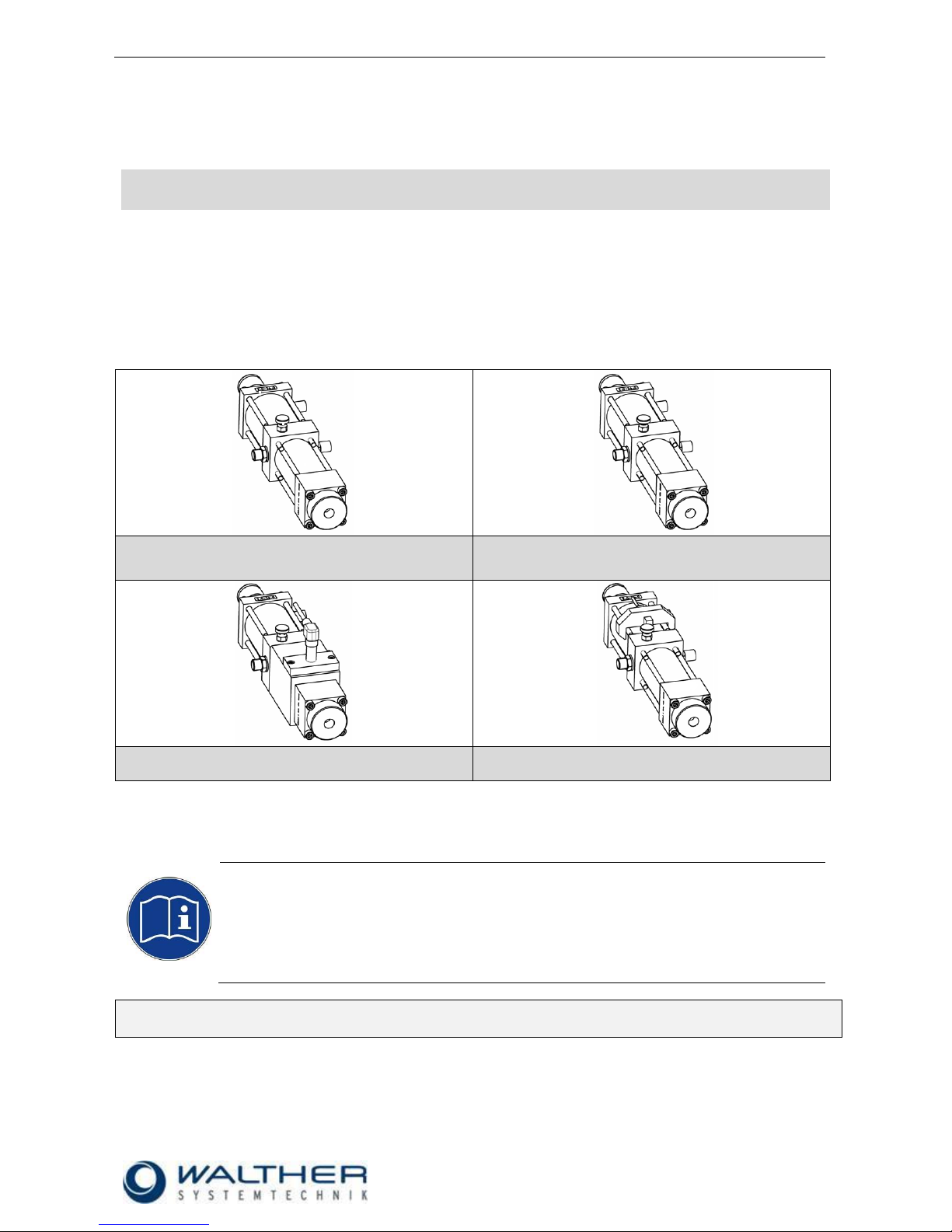
Assembly Instructions
Dosing Valve Station
Dosing Volume: 5.0 – 54.0 cm³
Article Number: 9741970.00 Standard
9741970.02 Magnetic Tape
9741970.03 Initiator
9741970.04 Magnet Tape and Proximity Switch
9741970.00
9741970.02
9741970.03
9741970.04
IMPORTANT
Please read this Assembly Instruction carefully before unpacking and start of operation with
the incomplete device, and make sure you follow it strictly!
The incomplete device will only be used, serviced or repaired by persons who are familiar
with the Assembly Instruction as well the guiding rules on work safety and accident
prevention.
Keep a translated version of the “Original Assembly Instructions“ at the incomplete device!
The instructions have to be available anytime!

Rev. 1.1
Assembly Instructions - Dosing Valve Station 9741970.0x
Page 2 of 31
Walther Systemtechnik GmbH – D 76726 Germersheim
Telefon: +49 (0)7274-7022-0 Telefax: +49 (0)7274-7022-91
http://www.walther-2000.de – info@walther-2000.de
Table of Contents
Page
EC DECLARATION OF INCORPORATION ....................................................................................................................... 4
1 SAFETY NOTES ................................................................................................................................................... 5
1.1 SYMBOLS FOR HAZARDS, DIRECTIVES AND INFORMATION .................................................................................................. 5
1.2 BASIC SAFETY DIRECTIONS ........................................................................................................................................... 6
1.3 RELEVANCE OF ASSEMBLY INSTRUCTIONS ....................................................................................................................... 6
1.4 RESPONSIBILITIES OF OPERATING COMPANY AND STAFF .................................................................................................... 6
1.5 TRAINING OF STAFF .................................................................................................................................................... 6
1.6 HAZARDS WHEN WORKING WITH THE DEVICE ................................................................................................................. 7
1.7 SAFETY HAZARDS CAUSED BY FLUIDS ............................................................................................................................. 7
1.8 SAFETY AND PROTECTION DEVICES ................................................................................................................................ 7
1.9 PERSONAL PROTECTIVE GEAR AND ADDITIONAL MEASURES ............................................................................................... 7
1.10 CORRECT USE ...................................................................................................................................................... 7
1.11 INCORRECT USE .................................................................................................................................................... 7
1.12 SERVICE, MAINTENANCE, TROUBLESHOOTING ............................................................................................................ 7
1.13 WARRANTY AND LIABILITY ...................................................................................................................................... 8
1.14 COPYRIGHT .......................................................................................................................................................... 8
1.15 QUALIFICATION OF PERSONNEL ............................................................................................................................... 8
2 TRANSPORT ....................................................................................................................................................... 9
2.1 PACKAGING .............................................................................................................................................................. 9
2.2 TASKS BEFORE TRANSPORT .......................................................................................................................................... 9
3 DESCRIPTION OF FUNCTION .............................................................................................................................. 9
3.1 PURPOSE OF THE PARTLY COMPLETED DEVICE ................................................................................................................. 9
3.2 TYPE LABEL .............................................................................................................................................................. 9
3.3 FUNCTIONAL DESCRIPTION ........................................................................................................................................ 10
3.4 VERSIONS .............................................................................................................................................................. 10
3.5 TOTAL VIEW / DESCRIPTION ....................................................................................................................................... 10
3.5.1 9741970.00 Standard ................................................................................................................................ 10
3.5.2 9741970.02 Magnetic Ring ....................................................................................................................... 11
3.5.3 9741970.03 Initiator .................................................................................................................................. 11
3.5.4 9741970.04 Magnetic Ring and Proximity Switch ..................................................................................... 11
3.6 TECHNICAL DATA ..................................................................................................................................................... 12
4 COMMISSIONING ............................................................................................................................................ 13
4.1 MOUNTING AND INSTALLATION .................................................................................................................................. 13
4.2 ADJUSTING THE INCOMPLETE DEVICE .......................................................................................................................... 13
5 OPERATION ..................................................................................................................................................... 14
5.1 GENERAL INFORMATION ........................................................................................................................................... 14
5.2 OPERATING ELEMENTS ............................................................................................................................................. 14
6 TAKING OUT OF SERVICE ................................................................................................................................. 15
6.1 SHORT INTERRUPTION .............................................................................................................................................. 15
6.2 LONG-TERM INTERRUPTION ....................................................................................................................................... 15
6.3 SHUTDOWN OF DEVICE ............................................................................................................................................. 15
7 MAINTENANCE AND REPAIR ............................................................................................................................ 16
7.1 GENERAL INFORMATION ........................................................................................................................................... 16
7.2 ROUTINE TASKS ....................................................................................................................................................... 16
7.3 CLEANING .............................................................................................................................................................. 16
7.4 SPARE PARTS .......................................................................................................................................................... 16
7.5 CUSTOMER SERVICE / SUPPORT .................................................................................................................................. 17
8 TROUBLESHOOTING ........................................................................................................................................ 17

Rev. 1.1
Assembly Instructions - Dosing Valve Station 9741970.0x
Page 3 of 31
Walther Systemtechnik GmbH – D 76726 Germersheim
Telefon: +49 (0)7274-7022-0 Telefax: +49 (0)7274-7022-91
http://www.walther-2000.de – info@walther-2000.de
8.1 GENERAL INFORMATION ........................................................................................................................................... 17
9 APPENDIX ........................................................................................................................................................ 18
9.1 DATA SHEET INDUCTIVE SENSOR (ARTICLE-NO. 9742369.01) ........................................................................................ 18
9.2 OPTION CABLE SOCKET FOR INDUCTIVE SENSOR (ARTICLE-NO. 9742369.11) .................................................................... 19
9.3 DATA SHEET PROXIMITY SWITCH, TYPE 102 160 (ARTICLE-NO. 9742451.01) .................................................................. 19
9.4 DIMENSIONED DRAWING DOSING VALVE STATION 9741970.00 ...................................................................................... 20
9.4.1 Spare Parts Drawing Dosing Valve Station 9741970.00 ............................................................................ 21
9.4.2 Spare Parts List Dosing Valve Station 9741970.00 .................................................................................... 22
9.5 DIMENSIONED DRAWING DOSING VALVE STATION 9741970.02 ...................................................................................... 23
9.5.1 Spare Parts Drawing Dosing Valve Station 9741970.02 ............................................................................ 24
9.5.2 Spare Parts List Dosing Valve Station 9741970.02 .................................................................................... 25
9.6 DIMENSIONED DRAWING DOSING VALVE STATION 9741970.03 ...................................................................................... 26
9.6.1 Spare Parts Drawing Dosing Valve Station 9741970.03 ............................................................................ 27
9.6.2 Spare Parts List Dosing Valve Station 9741970.03 .................................................................................... 28
9.7 DIMENSIONED DRAWING DOSING VALVE STATION 9741970.04 ...................................................................................... 29
9.7.1 Spare Parts Drawing Dosing Valve Station 9741970.04 ............................................................................ 30
9.7.2 Spare Parts List Dosing Valve Station 9741970.04 .................................................................................... 31
10 ACCESSORIES (OPTIONAL) ............................................................................................................................... 31

Rev. 1.1
Assembly Instructions - Dosing Valve Station 9741970.0x
Page 4 of 31
Walther Systemtechnik GmbH – D 76726 Germersheim
Telefon: +49 (0)7274-7022-0 Telefax: +49 (0)7274-7022-91
http://www.walther-2000.de – info@walther-2000.de
EC Declaration of Incorporation
in accordance with EU Machinery Directive 2006/42/EU, dated 17 May 2006, Appendix II B
We herewith confirm that the below mentioned incomplete device meets the basic requirements for safety
and health as stated in EU Machinery Directive 2006/42/EU for its design and construction as well as for the
configuration released by us on the market. This machine component will not be operated before it has been
determined that the incomplete system where the machine component will be installed also meets the
requirements of the Directive (2006/42/EG).
Manufacturer
Walther Systemtechnik GmbH
Hockenheimer Straße 3
76726 Germersheim
Description
Dosing Valve Station, Article-No. 9741970.00/02/03/04
We also declare the conformity with other, product-relevant directives/guidelines:
Mach. Direct. 2006/42/EU App. I, Clause: 1.1.2, 1.1.3, 1.1.5, 1.1.6, 1.3.2, 1.3.3,
1.3.4, 1.5.9
EMC- Directive 2014/30/EU, dated 26. February 2014
Applied harmonized standards, in particular:
DIN EN ISO 12100 Safety of Machinery – General Design Principles –
Risk Assessment and Risk Reduction (ISO
12100:2010)
In addition, we also confirm that the special documentation according to Appendix VII Part B has
been prepared.
The manufacturer, respectively his authorized representative obligates himself to submit this documentation
to the market surveillance authorities, if requested.
This EC Declaration of Incorporation becomes invalid if the incomplete device will be altered or changed
without consent of Walther Systemtechnik GmbH.
Authorized representative for Technical Documentation:
Stefan Hirl, Hockenheimer Straße 3, D- 76726 Germersheim
Germersheim, 19 April 2016
(Place, Date) (Stefan Hirl, Walther Systemtechnik GmbH, Mgmt)
Rev. 1.1
Assembly Instructions - Dosing Valve Station 9741970.0x
Page 5 of 31
Walther Systemtechnik GmbH – D 76726 Germersheim
Telefon: +49 (0)7274-7022-0 Telefax: +49 (0)7274-7022-91
http://www.walther-2000.de – info@walther-2000.de
1 Safety Notes
CAUTION
We kindly request that the customer studies the assembly instructions carefully, in
order to acquaint himself with the safe and efficient operation of this device. Please
keep this manual at a safe place for future reference.
The assembly instructions include important instructions and details for the safe and
appropriate operation of the device. It supports the operating and maintenance staff,
thus helping to reduce safety hazards, repair costs and down times, as well as to
enhance reliability and service life considerably. Therefore, it is important that every
person in charge of the device has access to this document.
1.1 Symbols for Hazards, Directives and Information
Symbols are used indicate dangerous situations and specific behavior. These symbols are also used in the
assembly instructions. All warning, danger and information symbols describe situations which can be harmful
to persons, material or environment if rules are not followed.
The assembly instructions use the following signs and symbols for dangers:
DANGER
Describes a potentially dangerous situation.
Death, grievous bodily harm or severe material damage WILL occur if the respective
measures of precaution have not been taken.
WARNING
Describes a potentially dangerous situation.
Death, grievous bodily harm or severe material damage MAY occur if the respective
measures of precaution have not been taken.
CAUTION
Describes a potentially dangerous situation.
Slight injuries CAN occur if the respective measures of precaution have not been taken.
This signal word is also used to describe possible property damages.
IMPORTANT
Indicates tips for usage and other particularly useful information.
No dangerous situation.

Rev. 1.1
Assembly Instructions - Dosing Valve Station 9741970.0x
Page 6 of 31
Walther Systemtechnik GmbH – D 76726 Germersheim
Telefon: +49 (0)7274-7022-0 Telefax: +49 (0)7274-7022-91
http://www.walther-2000.de – info@walther-2000.de
1.2 Basic Safety Directions
The basic requirements for safe handling and trouble-free operation of this device include:
CAUTION
The device must not be used for purposes other than those intended.
The device must not be modified. In case of modifications, the customer takes
on all responsibility for any incidents due to his modifications. In case a
modification of the device is required, please contact WALTHER
SYSTEMTECHNIK GMBH.
Make sure that the device is always in safe operation condition. Qualified staff
shall perform functional tests and checks for damage at regular intervals.
Authorized staff only shall do disassembly, and according to these assembly
instructions only. To ensure appropriate expertise of the customer´s staff, we
offer training courses upon request.
The customer is responsible for complying with all appropriate safety
measures.
Never operate the device if outlets point towards a person.
Always disconnect device from mains / air pressure supply / grease feed pipe
before beginning any maintenance work. All piping and hoses must be
pressureless.
Check all pipes, hoses and screw connectors for leaks and visible damage at
regular intervals! Immediately remove any damage!
Exposure of the sensors to magnetic fields may cause malfunction of the
sensors.
Ensure that working place, device and environment are kept in clean and
clearly arranged state at regular intervals.
Rules and regulations regarding the prevention of accidents that apply to the
working site must be observed.
1.3 Relevance of Assembly Instructions
The assembly instructions are only referring to the device as stated on the cover sheet of this manual.
The manufacturer of the device accepts responsibility for the safety, reliability and performance of the device
only if the user has read and signed the assembly instructions.
Kindly remember that the assembly instructions were designed for your personal protection and safety.
Reading and understanding the instructions may further help to avoid expensive service work and
inappropriate operation of the device, and hence substantially increase the customer´s benefit.
1.4 Responsibilities of Operating Company and Staff
Reliable and trained staff only should be authorized to work with the device, and responsibilities
should be clearly assigned to individuals.
Maintenance of electrical components of the device must be performed by a professional electrician,
or under supervision of a professional electrician, and according to electro-technical regulations.
Maintenance of hydraulic equipment should be assigned to staff with hydraulics know-how and experi-
ence only!
1.5 Training of Staff
Persons must not work with the device unless they have been respectively trained and made familiar
with the device.
Responsibilities of personnel for assembly work, commissioning, operation, setting up, maintenance,
transport and repair should be clearly assigned to individuals.
Persons in training may work with the device under supervision of an experienced person only.
Rev. 1.1
Assembly Instructions - Dosing Valve Station 9741970.0x
Page 7 of 31
Walther Systemtechnik GmbH – D 76726 Germersheim
Telefon: +49 (0)7274-7022-0 Telefax: +49 (0)7274-7022-91
http://www.walther-2000.de – info@walther-2000.de
1.6 Hazards when Working with the Device
All equipment and devices are built to the state of the art and according to accredited safety rules.
Nevertheless, safety hazards to the user or third persons, or deficiencies of the plant or its parts may occur, if
the device is not properly used.
The device must only be used:
for its intended purpose;
if working condition of device ensures full technical safety.
Technical faults, which may degrade safety, must be repaired immediately!
1.7 Safety Hazards caused by Fluids
NOTE
Pay close attention to the safety directions specified by the fluid manufacturer and
observe his instructions.
The manufacturer of this device refuses to accept any liability for incidents caused by
disregarding directions, instructions or recommendations given by the manufacturer.
1.8 Safety and Protection Devices
Make sure that all protection devices are installed properly and are in functional condition, prior to start-
up of the device.
Protection devices must not be removed unless the device has been shut down and a safeguard against
restart has been established.
1.9 Personal Protective gear and Additional Measures
The operator company is responsible for providing the required personal protective gear.
All safety devices and installations should be checked at regular intervals.
1.10 Correct Use
The device must be used under the specified operating conditions only. The device must be used exclusively for
conveying lubricants according to the detailed specifications in chapter 2.1 of the assembly instructions. Any
usage other than or beyond that specified herein is regarded as not according to the intended purpose. The
manufacturer company assumes no responsibility for any damage resulting from such incorrect use.
Correct use of the device also includes:
Observing and adhering to all assembly instructions stated in this manual.
Adherence to inspection and maintenance tasks.
1.11 Incorrect Use
The manufacturer company assumes no responsibility for any damage resulting from inappropriate usage.
Incorrect use of the device includes but is not limited to:
Conveying any medium not specified in this manual or in writing by the manufacturer;
Using corrosive and / or curing agents;
Conveying, handling or storing foods with the device.
1.12 Service, Maintenance, Troubleshooting
The specified calibration and maintenance work should be performed timely according to the mainte-
nance schedule.
Inform operators prior to execution of calibration and maintenance work.
Disconnect device from mains supply and safeguard against unintentional restart (warning sign: “Do not
switch on!”).
Make sure that all screw connections and fittings are fastened tightly.
After completion of maintenance work, check all functions and all safety devices.
Rev. 1.1
Assembly Instructions - Dosing Valve Station 9741970.0x
Page 8 of 31
Walther Systemtechnik GmbH – D 76726 Germersheim
Telefon: +49 (0)7274-7022-0 Telefax: +49 (0)7274-7022-91
http://www.walther-2000.de – info@walther-2000.de
1.13 Warranty and Liability
In principle, our general business and delivery terms apply as well as any written agreements prior to
ordering. All warranty and liability claims in case of personal or material damage are excluded if they are
caused by one or more of the following reasons:
Incorrect use of the device.
Work on device by persons other than those authorized to work with the device.
Improper transport, storage, assembly, commissioning, operation or maintenance of device.
Operation of the device with faulty, not properly fitted or nonfunctional safety and protection devices.
Disregard of instructions regarding safety, transport, storage, assembly, operation, commissioning,
maintenance and setting-up of the device as stated in the assembly instructions.
Modifications of the device not authorized by the manufacturer company.
Manipulation of the pressure control device or the supply pressure without authorization of the manufac-
turer company.
Insufficient inspection of device parts subject to wear.
Improper repairs and use of spare parts from other suppliers.
Disasters, e.g. by forces of nature or foreign object damage.
1.14 Copyright
The copyright of the assembly instructions belongs to Walther Systemtechnik GmbH. The assembly
instructions are intended for use by the staff of the user company only.
Directions and instructions contained in this manual must not be copied, nor distributed, nor communicated
to third parties, neither completely nor partly.
1.15 Qualification of Personnel
Only trained and instructed personnel may conduct work on the equipment.
The responsibilities of the personnel for assembly work, operation, repair work or maintenance work must be
clearly assigned to individuals!
Persons in training may work with the equipment under supervision of an experienced person only.
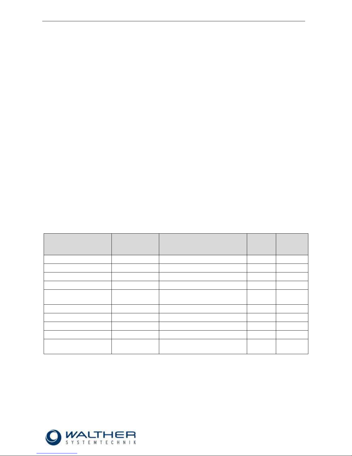
Personnel
Task
Trained
Personnel
Personnel with Technical
Qualification
Specialist
Supervisor
Packaging, Transport
X
-
-
-
Commissioning
X
X
-
Operation
X
-
Troubleshooting, general
X
X
-
Troubleshooting,
mechanical
-
X
-
-
Troubleshooting, electrical
-
-
X
-
Setting up
-
X
-
-
Maintenance
-
X
-
-
Repair
-
X
X
-
Taking out of service,
Storage
-
X
X
-
Rev. 1.1
Assembly Instructions - Dosing Valve Station 9741970.0x
Page 9 of 31
Walther Systemtechnik GmbH – D 76726 Germersheim
Telefon: +49 (0)7274-7022-0 Telefax: +49 (0)7274-7022-91
http://www.walther-2000.de – info@walther-2000.de
2 Transport
2.1 Packaging
The type of packaging will be selected according to the mode of transport. If not separately negotiated, the
packaging will be made in accordance with the packaging directive of company Walther Systemtechnik
GmbH. This directive complies with HPE Packaging Regulations.
2.2 Tasks before Transport
The following tasks have to be fulfilled before the actual transport.
Disconnect energy supply lines
Extreme care has to be applied when transporting the incomplete machine and its individual parts in order to
avoid damages from external impacts or careless on- and off-loading. Depending on type and duration of
transport, appropriate transport securing devices have to be used. The incomplete device itself will be
adjusted and leveled by appropriate fastening elements.
3 Description of Function
3.1 Purpose of the Partly Completed Device
The special construction supplies the correct lubricant in the required quantity at a given time to a defined
location. The dosing valves are also suitable for the use with oil.
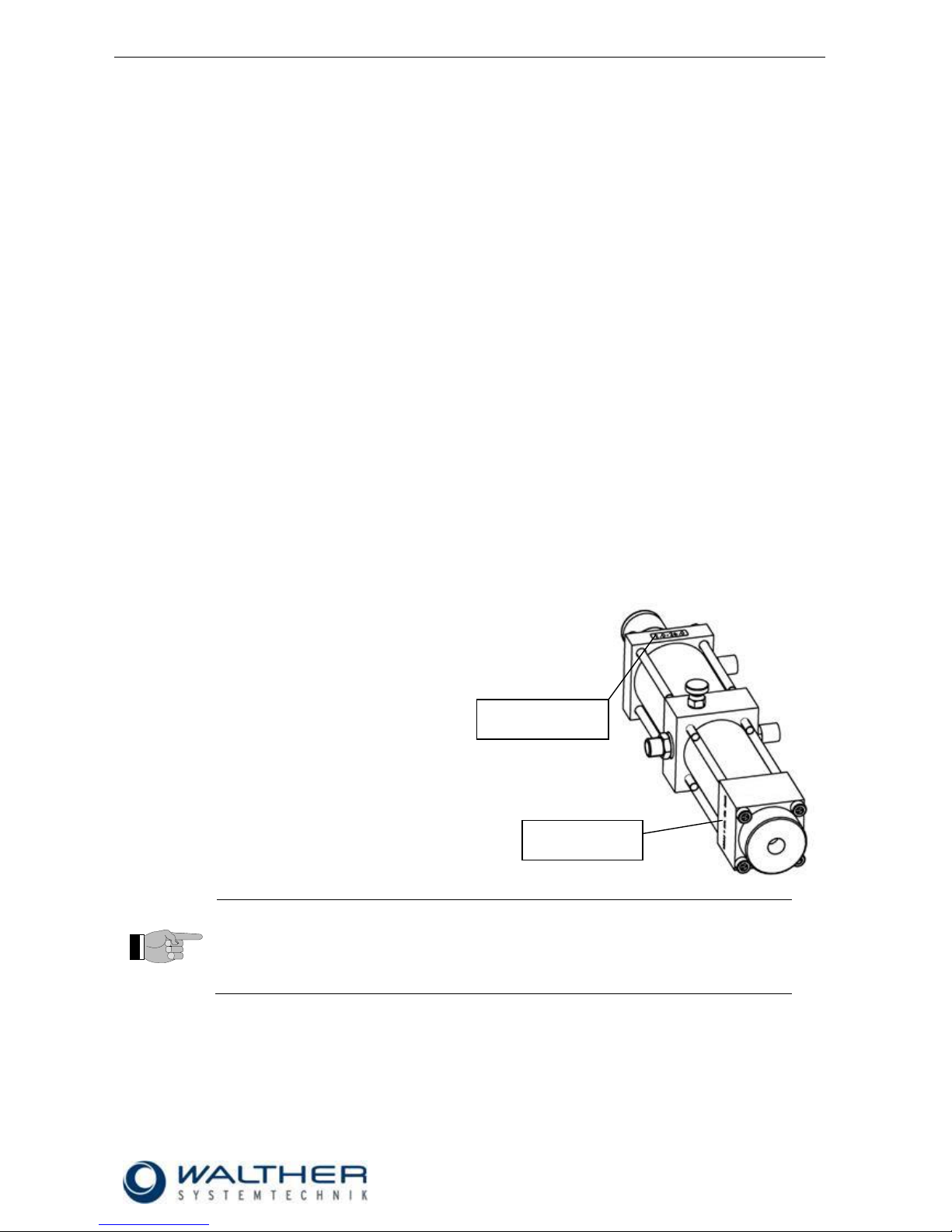
3.2 Type Label
The dosing Valve Station can be identified by an
engraving on the side of the casing which shows the
manufacturing date and also the article number.
Above that it has a type label; this contains more
information for indentifying the device.
IMPORTANT
Always use the engraved data and the data from the type label for spare part orders or
the technical service.
Type Label
Engraving
Rev. 1.1
Assembly Instructions - Dosing Valve Station 9741970.0x
Page 10 of 31
Walther Systemtechnik GmbH – D 76726 Germersheim
Telefon: +49 (0)7274-7022-0 Telefax: +49 (0)7274-7022-91
http://www.walther-2000.de – info@walther-2000.de
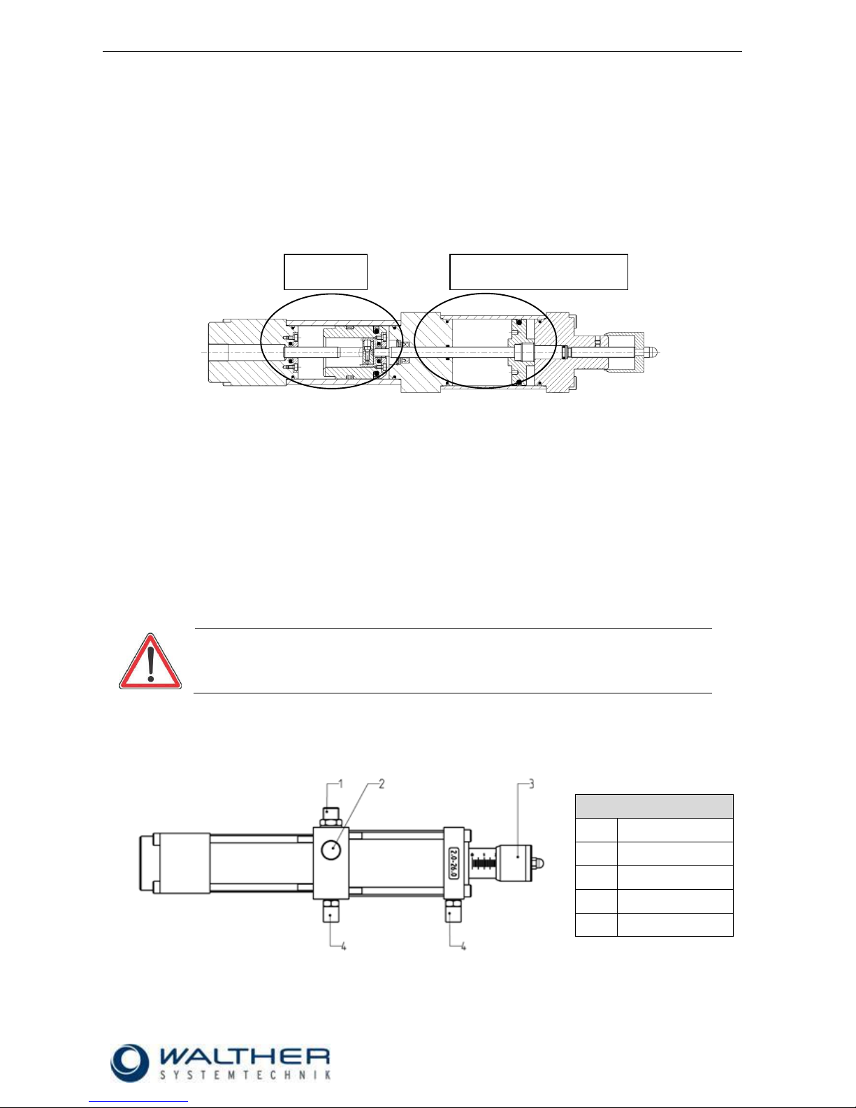
3.3 Functional Description
The pneumatic part of the dosing valve is controlled by a pneumatic 5/2-way valve which is integrated in the
handle. Pulling the trigger initiates the grease dosing. The dosing pressure is depending on the pressure in
the grease (medium). The air and grease chambers are separated.
In order to obtain a high quality and precision of repeating during the actual dosing, the whole cycle has to
be completed. In other words, the control piston has to move from the initial position to the dosing position
and back into the initial position.
.
3.4 Versions
9741970.00 Standard Version
9741970.02 Magnetic Tape at air piston as front part for proximity switch
9741970.03 Initiator for controlling the dosing piston. This special construction increases the process
safety. The initiator will send an electric signal once the cycle has been completed, i.e. when
the grease has been released.
For a process-safe function of the initiator, the smallest selected dosing amount has to be
approx. 10% larger then minimum quantity indicated on the valve.
When dosing in the lower limit area, we recommend using the next small valve!
9741970.04 Magnetic Tape at air piston and proximity switch at valve. The special construction increases
the process safety. The proximity switch will send an electric signal once the cycle has been
completed; air piston in the initial position.
CAUTION
For a process-safe function of the initiator, the smallest selected dosing amount has to
be approx. 10% larger then minimum quantity indicated on the valve.
3.5 Total View / Description
3.5.1 9741970.00 Standard
Key
Pos.
Description
1
Connection grease
2
Ventilation
3
Adjusting sleeve
4
Connection air
Pneumatic Part
Grease
Part
Rev. 1.1
Assembly Instructions - Dosing Valve Station 9741970.0x
Page 11 of 31
Walther Systemtechnik GmbH – D 76726 Germersheim
Telefon: +49 (0)7274-7022-0 Telefax: +49 (0)7274-7022-91
http://www.walther-2000.de – info@walther-2000.de
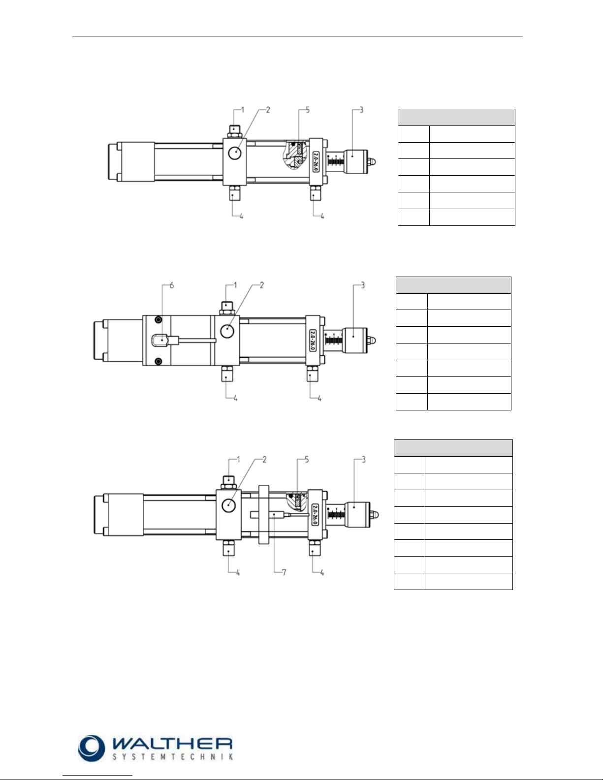
3.5.2 9741970.02 Magnetic Ring
Key
Pos.
Description
1
Connection grease
2
Ventilation
3
Adjusting sleeve
4
Connection air
5
Magnetic Tape
3.5.3 9741970.03 Initiator
Key
Pos.
Description
1
Connection grease
2
Ventilation
3
Adjusting sleeve
4
Connection air
5
-- 6 Initiator
3.5.4 9741970.04 Magnetic Ring and Proximity Switch
Key
Pos.
Description
1
Connection grease
2
Ventilation
3
Adjusting sleeve
4
Connection air
5
Magnetic tape
6
-- 7 Proximity switch

Rev. 1.1
Assembly Instructions - Dosing Valve Station 9741970.0x
Page 12 of 31
Walther Systemtechnik GmbH – D 76726 Germersheim
Telefon: +49 (0)7274-7022-0 Telefax: +49 (0)7274-7022-91
http://www.walther-2000.de – info@walther-2000.de
3.6 Technical Data
Article Number
9741970.00
9741970.02
Version
Standard
Magnetic ring
Dosing range [cm³]
5.0 – 54,0
5.0 – 54.0
Weight [kg]
2.56
2.59
Connection P inner thread
G ¼
G ¼
Connection A inner thread
G ¼
G ¼
Connection 2 and 4 inner thread hose
G 1/8 M8
G 1/8 M8
Max. operating pressure [bar]
200
200
Operating pressure material outlet [bar]
80
80
Min. pneumatic operating pressure [bar]
5
5
Max. pneumatic operating pressure [bar]
7
7
Optimum pneumatic operating pressure [bar]
6
6
Operating voltage range [VDC]
Power consumption [A]
Max. load current [A]
Protection type IAW DIN 40050
Display
Article Number
9741970.03
9741970.04
Version
Initiator
Magnetic ring and Proximity
Switch
Dosing range [cm³]
5.0 – 54.0
5.0 – 54.0
Weight [kg]
2.86
2.64
Connection P inner thread
G ¼
G ¼
Connection A inner thread
G ¼
G ¼
Connection 1 inner thread
G 1/8 M8
G 1/8 M5
Max. operating pressure [bar]
200
200
Operating pressure material outlet [bar]
80
80
Min. pneumatic operating pressure [bar]
5
5
Max. pneumatic operating pressure [bar]
7
7
Optimum pneumatic operating pressure [bar]
6
6
Max. switched current [A]
0.2
0.5
Max. switched voltage [V]
10 – 30
12 – 24
Max. switching capacity [W / VA]
-
10 / 12
Protection type IAW DIN 40050
IP 68/67
IP 67
Display
LED
LED

Rev. 1.1
Assembly Instructions - Dosing Valve Station 9741970.0x
Page 13 of 31
Walther Systemtechnik GmbH – D 76726 Germersheim
Telefon: +49 (0)7274-7022-0 Telefax: +49 (0)7274-7022-91
http://www.walther-2000.de – info@walther-2000.de
4 Commissioning
4.1 Mounting and Installation
IMPORTANT
We recommend a front-end maintenance unit for the control air.
4.2 Adjusting the Incomplete Device
IMPORTANT
Make sure that the air pressure for the control air is at approx. 6 bar. This guarantees
an optimum function of the valves.
The material inlet pressure should not rise above 200 bar. Check also the pressure
ratio of the feeder pump. A pressure reduction valve will help you to easily control the
supply pressure (a pressure reduction valve is an advantage but not mandatory, if
pressure stays below 200 bar).
IMPORTANT
All dosing valves will be checked at our factory before delivery. It may therefore happen that some residues from the test media remain in the valve.
1) Fill lubricant supply hoses with lubricant before connecting a dosing valve (ventilating). Then connect
supply hoses and control air according to layout.
2) Set maximum dosing amount (turn adjusting sleeve to the far outside) when first starting the device.
3) If adjusting sleeve cannot be turned, operate rerouting valve. You can now operate the adjusting
sleeve.
4) After the first release of lubricant, the desired dosing quantity can be set through the adjusting
sleeve.
5) Keep the distance between dosing valve and greasing area as little as possible. This will increase
the precision for dosing and repetition.
6) The possible cycle time depends on the viscosity of the lubricant and the material pressure.
7) The dosing valves can be fastened with 2 M6 screws.
8) The dosing quantity is continuously variable through the dosing screw.
9) Please note that there are 2 switching points per magnetic field when installing the dosing sensors
(optional).
Grease
Control air

Rev. 1.1
Assembly Instructions - Dosing Valve Station 9741970.0x
Page 14 of 31
Walther Systemtechnik GmbH – D 76726 Germersheim
Telefon: +49 (0)7274-7022-0 Telefax: +49 (0)7274-7022-91
http://www.walther-2000.de – info@walther-2000.de
5 Operation
5.1 General Information
The partly completed machine may only be operated if the safety-related equipment is permanently effective
and not suspended during operation or altered in its intended purpose/function.
5.2 Operating Elements
Adjusting screw

Rev. 1.1
Assembly Instructions - Dosing Valve Station 9741970.0x
Page 15 of 31
Walther Systemtechnik GmbH – D 76726 Germersheim
Telefon: +49 (0)7274-7022-0 Telefax: +49 (0)7274-7022-91
http://www.walther-2000.de – info@walther-2000.de
6 Taking out of Service
6.1 Short Interruption
A clean-spraying should be performed for short interruptions (15 min or more)
IMPORTANT
Please observe the maintenance instructions!
6.2 Long-term Interruption
The following has to be observed for a long-term interruption of the device:
No pressure shall be left in system (check displays).
IMPORTANT
Please observe the maintenance instructions!
6.3 Shutdown of Device
The following has to be observed for a final shutdown of the device:
Disconnect the main power plug.
No pressure shall be left in the system (check displays).
Dispose properly of grease/oil.
Clean dosing valve with special thinner
CAUTION
Danger of accidents and environmental pollution. Do not spill grease / oil. Dispose
properly of grease / oil (hazardous waste).
IMPORTANT
Please observe the maintenance instructions!

Rev. 1.1
Assembly Instructions - Dosing Valve Station 9741970.0x
Page 16 of 31
Walther Systemtechnik GmbH – D 76726 Germersheim
Telefon: +49 (0)7274-7022-0 Telefax: +49 (0)7274-7022-91
http://www.walther-2000.de – info@walther-2000.de
7 Maintenance and Repair
7.1 General Information
CAUTION
Before starting any maintenance or repair work, ensure that all air-operated tools are
depressurized and disconnected from the air supply.
Disconnect the main power plug.
Make sure the pneumatic / hydraulic system is pressure-less.
IMPORTANT
This chapter does not cover how to repair the device after damage. Repair work should
only be performed by a specialized technician or the maintenance team or the
manufacturer.
7.2 Routine Tasks
The maintenance intervals below refer to a single-shift operation. If the device is run in a multi-shift operation
or is operated very often, the maintenance intervals become shorter. Also, additional factors such as
cleanliness or work surroundings have to be taken into account.
WHEN
WHAT
HOW
WHO
Weekly
Check dosing valve for
tightness
visual
Specialists
Weekly
Check all screw and
fitting connections for
tightness
visual
Specialists
Monthly
Check conductors for
damages
visual
Specialists
CAUTION
Check all functions and safety-related parts for readiness after maintenance if finished.
7.3 Cleaning
Only use soft brushes for outside cleaning of the nozzle tips. Never use metal tools
with sharp edges.
7.4 Spare Parts
IMPORTANT
Only use original spare parts from the manufacturer!
Wrong or defective spare parts from other manufacturers can damage the device. If
other than original spare parts of the manufacturer will be used, all obligations from the
manufacturer or his sales partners, such as guarantees, service contracts etc will be
forfeited without further notice.

Rev. 1.1
Assembly Instructions - Dosing Valve Station 9741970.0x
Page 17 of 31
Walther Systemtechnik GmbH – D 76726 Germersheim
Telefon: +49 (0)7274-7022-0 Telefax: +49 (0)7274-7022-91
http://www.walther-2000.de – info@walther-2000.de
7.5 Customer Service / Support
Walther Systemtechnik GmbH
Hockenheimer Straße 3
D-76726 Germersheim
Germany
Phone ++49(0)7274-7022-0
Fax ++49(0)7274-7022-91
Email info@walther-2000.de
Internet www.walther-2000.de
8 Troubleshooting
8.1 General Information
IMPORTANT
First check all supply lines for connection and serviceability.
All below mentioned failures or problems will only be corrected/repaired by a specialist.
In case of serious problems that cannot be resolved, please contact the Walther Systemtechnik GmbH
customer service.
Problem
Possible cause
Action
The valve works but no
lubricating medium is
ejected
Does the supply pump
transport lubricant?
If pump does not work anymore, refer to operating
manual of pump.
Check the ventilating screws in the supply pump
(see operating manual of pump).
Leakage
Check dosing valve
Continuous signal from
sensor
Initiator defective
Replace initiator
Dosing piston not in end
position
Check dosing valve; check setting of dosing
volume
No signal from sensor
Broken cable
Replace cable
Initiator defective
Replace initiator
Loose connector
Check connection
Loose holder
Fix holder
Loose initiator in holder
Fasten initiator to the holder
Permanent signal from
proximity switch
Air piston permanently
in initial position
Check dosing valve
Proximity switch
defective
Replace proximity switch
No signal from proximity
switch
Air piston not in initial
position or defective
Check dosing valve
LED defective
LED or sensor defective
Exchange cable, replace initiator
Air in system
Air pockets in grease
container.
Air pockets in hoses.
Disconnect supply hoses from dosing valve; let
grease emerge, then re-connect hoses again. Restart with max. dosing quantity.

Rev. 1.1
Assembly Instructions - Dosing Valve Station 9741970.0x
Page 18 of 31
Walther Systemtechnik GmbH – D 76726 Germersheim
Telefon: +49 (0)7274-7022-0 Telefax: +49 (0)7274-7022-91
http://www.walther-2000.de – info@walther-2000.de
9 Appendix
9.1 Data Sheet Inductive Sensor (Article-No. 9742369.01)
Rev. 1.1
Assembly Instructions - Dosing Valve Station 9741970.0x
Page 19 of 31
Walther Systemtechnik GmbH – D 76726 Germersheim
Telefon: +49 (0)7274-7022-0 Telefax: +49 (0)7274-7022-91
http://www.walther-2000.de – info@walther-2000.de
9.2 Option Cable Socket for Inductive Sensor (Article-No. 9742369.11)
Cable length 5m
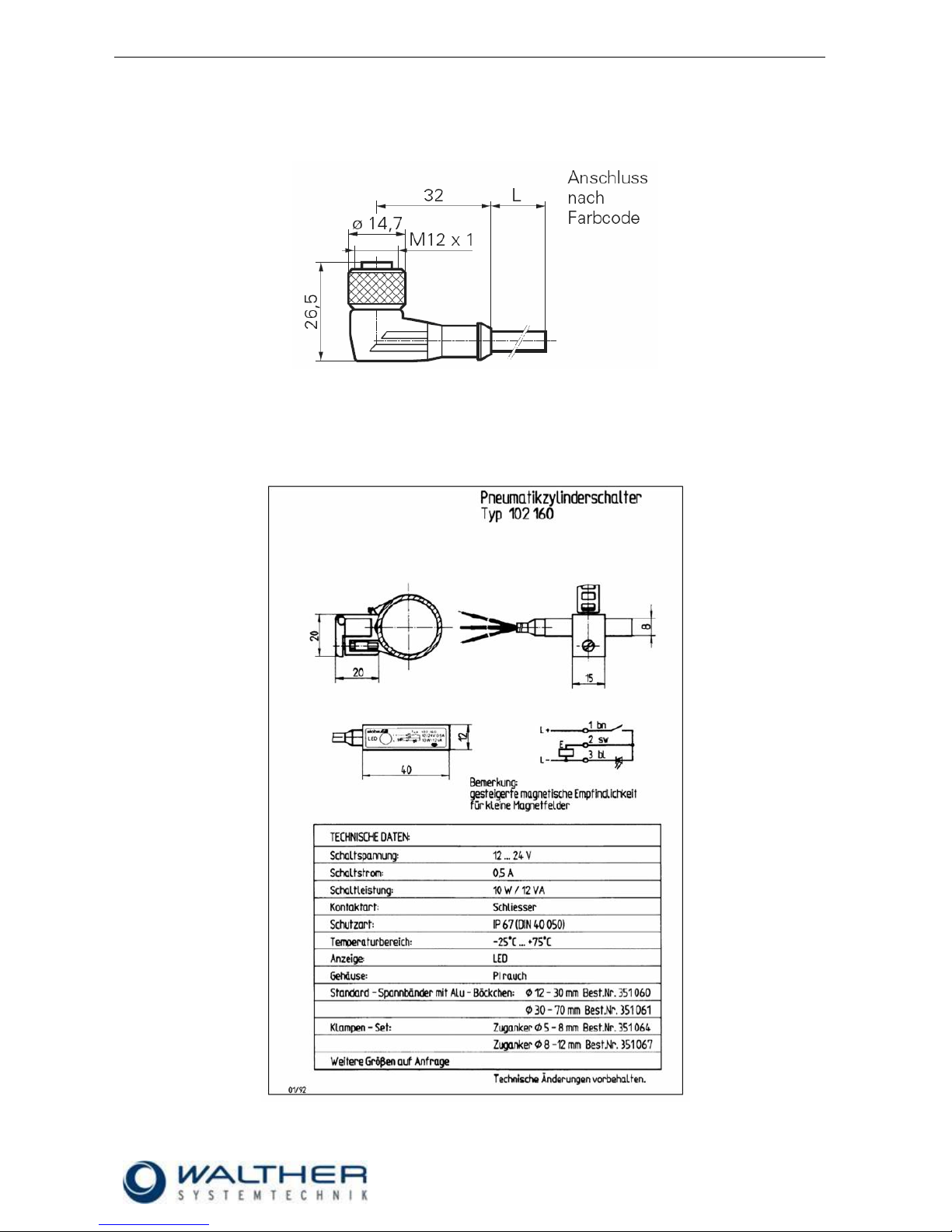
9.3 Data Sheet Proximity Switch, Type 102 160 (Article-No. 9742451.01)

Rev. 1.1
Assembly Instructions - Dosing Valve Station 9741970.0x
Page 20 of 31
Walther Systemtechnik GmbH – D 76726 Germersheim
Telefon: +49 (0)7274-7022-0 Telefax: +49 (0)7274-7022-91
http://www.walther-2000.de – info@walther-2000.de
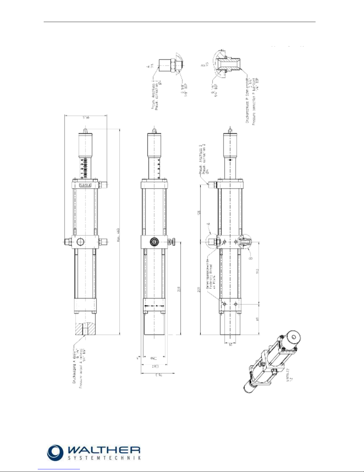
9.4 Dimensioned Drawing Dosing Valve Station 9741970.00
0
Rev. 1.1
Assembly Instructions - Dosing Valve Station 9741970.0x
Page 21 of 31
Walther Systemtechnik GmbH – D 76726 Germersheim
Telefon: +49 (0)7274-7022-0 Telefax: +49 (0)7274-7022-91
http://www.walther-2000.de – info@walther-2000.de
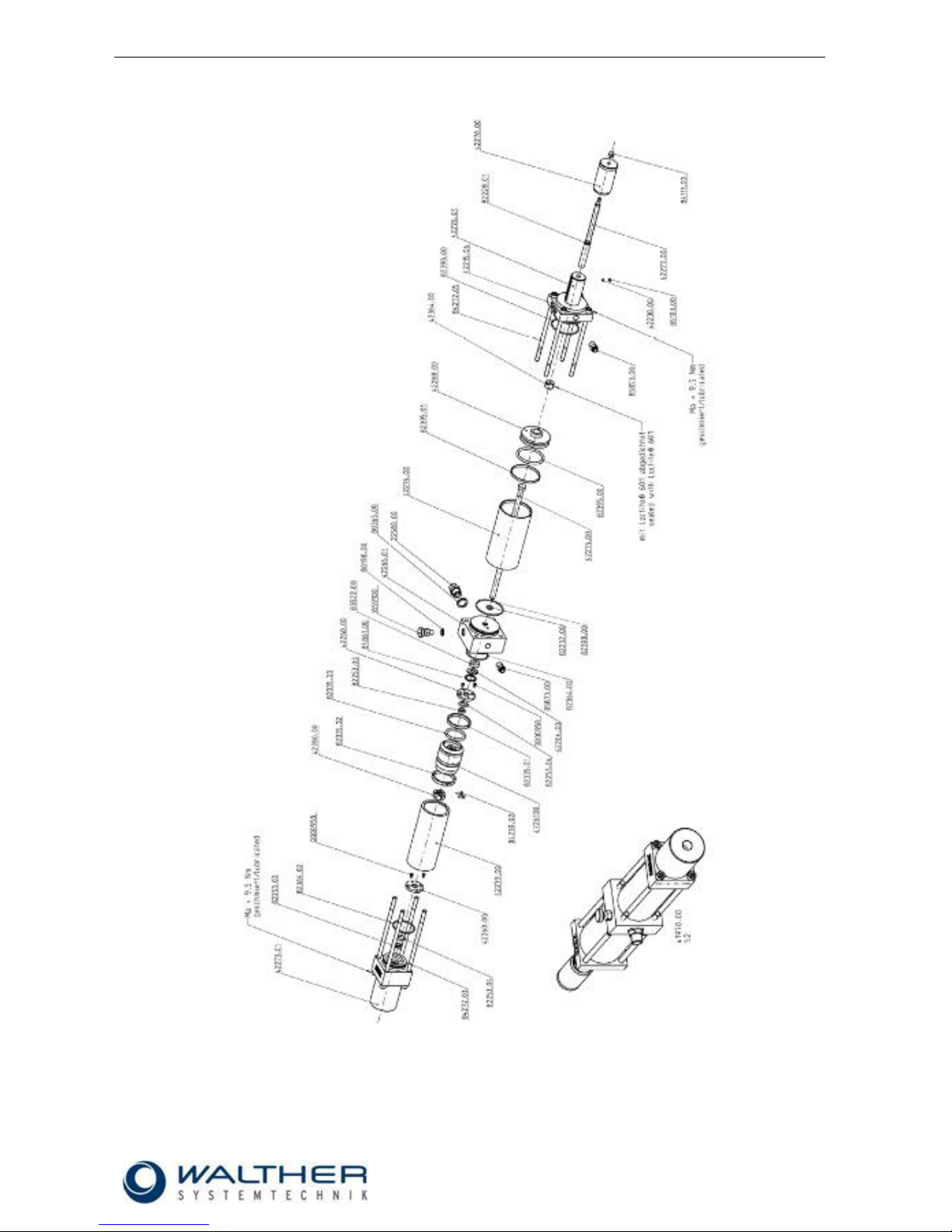
9.4.1 Spare Parts Drawing Dosing Valve Station 9741970.00
Make sure all order numbers are preceded by a „97“!

Rev. 1.1
Assembly Instructions - Dosing Valve Station 9741970.0x
Page 22 of 31
Walther Systemtechnik GmbH – D 76726 Germersheim
Telefon: +49 (0)7274-7022-0 Telefax: +49 (0)7274-7022-91
http://www.walther-2000.de – info@walther-2000.de
9.4.2 Spare Parts List Dosing Valve Station 9741970.00
Artikelnummer
Bezeichnung
Description
Menge/pieces
970000958
Zylinderschraube
Hexagon screw
4
9722580.00
Gewindestück
Connecting piece
1
9735591.00
Entlüftungsventil
Air release valve
1
9741969.00
Dichtungssatz
Seal kit
1
9742215.06
Schild 5.00-54.00
Sign 5.00-54.00
1
9742238.00
Gummistück
Rubber stopper
1
9742260.00
Dichtscheibe
Sealing disc
2
9742261.00
Dosierkolben
Metering piston
1
9742264.00
Scheibe
Disc
1
9742265.01
Mittelstück
Centerpiece
1
9742268.00
Steuerkolben
Control piston
1
9742273.01
Anschlussstück
Connecting piece
1
9742274.00
Zylinder
Cylinder
1
9742275.00
Ventilstange
Valve rod
1
9742276.01
Endstück En
End section
1
9742277.00
Dosierschraube
Metering screw
1
9742278.00
Regulierhülse
Metering sleeve
1
9742279.00
Druckzylinder
Hydraulic cylinder
1
9742280.00
Stellring Paar
Set collar
1
9742364.00
Gewindestift
Set screw
1
9780198.00
Dichtung
Seal
1
9780365.00
Dichtung
Seal
1
9782228.01
O-Ring
O-ring
1
9782232.00
O-Ring
O-ring
1
9782253.03
Glydring
Glydring
2
9782253.04
O-Ring
O-ring
2
9782335.01
Glydring
Glydring
1
9782335.02
Slydring
Slydring
1
9782335.03
O-Ring
O-ring
1
9782364.02
O-Ring
O-ring
2
9782395.00
O-Ring
O-ring
1
9782395.01
Glydring
Glydring
1
9782398.00
O-Ring
O-ring
2
9783522.00
Nutring
Slotring
1
9784111.00
Hutmutter
Cap nut
1
9784239.02
Zylinderschraube
Hexagon screw
2
9784272.03
Zylinderschraube
Hexagon screw
4
9784272.05
Zylinderschraube
Hexagon screw
4
9784861.00
Sicherungsring
Retaining ring
2
9785081.00
Gewindestift
Set screw
2
9785103.00
Gewindestift
Set screw
2
9785873.00
Schnellverschraubung
Fitting
4
Rev. 1.1
Assembly Instructions - Dosing Valve Station 9741970.0x
Page 23 of 31
Walther Systemtechnik GmbH – D 76726 Germersheim
Telefon: +49 (0)7274-7022-0 Telefax: +49 (0)7274-7022-91
http://www.walther-2000.de – info@walther-2000.de
9.5 Dimensioned Drawing Dosing Valve Station 9741970.02

Rev. 1.1
Assembly Instructions - Dosing Valve Station 9741970.0x
Page 24 of 31
Walther Systemtechnik GmbH – D 76726 Germersheim
Telefon: +49 (0)7274-7022-0 Telefax: +49 (0)7274-7022-91
http://www.walther-2000.de – info@walther-2000.de
9.5.1 Spare Parts Drawing Dosing Valve Station 9741970.02
Make sure all order numbers are preceded by a „97“!

Rev. 1.1
Assembly Instructions - Dosing Valve Station 9741970.0x
Page 25 of 31
Walther Systemtechnik GmbH – D 76726 Germersheim
Telefon: +49 (0)7274-7022-0 Telefax: +49 (0)7274-7022-91
http://www.walther-2000.de – info@walther-2000.de
9.5.2 Spare Parts List Dosing Valve Station 9741970.02
Artikelnummer
Bezeichnung
Description
Menge/pieces
970000958
Zylinderschraube
Hexagon screw
4
9722580.00
Gewindestück
Connecting piece
1
9735591.00
Entlüftungsventil
Air release valve
1
9741969.00
Dichtungssatz
Seal kit
1
9742215.06
Schild 5.00-54.00
Sign 5.00-54.00
1
9742238.00
Gummistück 1
Rubber stopper
1
9742260.00
Dichtscheibe
Sealing disc
2
9742261.00
Dosierkolben
Metering piston
1
9742264.00
Scheibe
Disc
1
9742265.01
Mittelstück
Centerpiece
1
9742268.00
Steuerkolben
Control piston
1
9742273.01
Anschlussstück
Connecting piece
1
9742274.00
Zylinder
Cylinder
1
9742275.00
Ventilstange
Valve rod
1
9742276.01
Endstück
End section
1
9742277.00
Dosierschraube
Metering screw
1
9742278.00
Regulierhülse
Metering sleeve
1
9742279.00
Druckzylinder
Hydraulic cylinder
1
9742280.00
Stellring Paar
Set collar
1
9742283.00
Ring
Ring
1
9742364.00
Gewindestift
Set screw
1
9742392.00
Plastikmagnet
Magnetic ring
1
9780198.00
Dichtung
Seal
1
9780365.00
Dichtung
Seal
1
9782228.01
O-Ring
O-ring
1
9782232.00
O-Ring
O-ring
1
9782253.03
Glydring
Glydring
2
9782253.04
O-Ring
O-ring
2
9782335.01
Glydring
Glydring
1
9782335.02
Slydring
Slydring
1
9782335.03
O-Ring
O-ring
1
9782364.02
O-Ring
O-ring
2
9782395.00
O-Ring
O-ring
1
9782395.01
Glydring
Glydring
1
9782398.00
O-Ring
O-ring
2
9783522.00
Nutring
Slotring
1
9784111.00
Hutmutter
Cap nut
1
9784239.02
Zylinderschraube
Hexagon screw
2
9784272.03
Zylinderschraube
Hexagon screw
4
9784272.05
Zylinderschraube
Hexagon screw
4
9784861.00
Sicherungsring
Retaining ring
1
9785103.00
Gewindestift
Set screw
1
9785873.00
Schnellverschraubung
Fitting
2

Rev. 1.1
Assembly Instructions - Dosing Valve Station 9741970.0x
Page 26 of 31
Walther Systemtechnik GmbH – D 76726 Germersheim
Telefon: +49 (0)7274-7022-0 Telefax: +49 (0)7274-7022-91
http://www.walther-2000.de – info@walther-2000.de
9.6 Dimensioned Drawing Dosing Valve Station 9741970.03

Rev. 1.1
Assembly Instructions - Dosing Valve Station 9741970.0x
Page 27 of 31
Walther Systemtechnik GmbH – D 76726 Germersheim
Telefon: +49 (0)7274-7022-0 Telefax: +49 (0)7274-7022-91
http://www.walther-2000.de – info@walther-2000.de
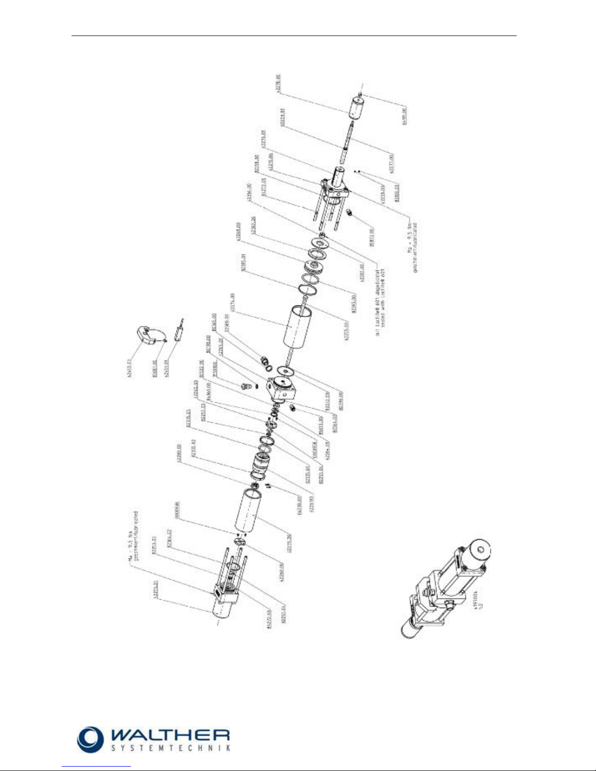
9.6.1 Spare Parts Drawing Dosing Valve Station 9741970.03
Make sure all order numbers are preceded by a „97“!

Rev. 1.1
Assembly Instructions - Dosing Valve Station 9741970.0x
Page 28 of 31
Walther Systemtechnik GmbH – D 76726 Germersheim
Telefon: +49 (0)7274-7022-0 Telefax: +49 (0)7274-7022-91
http://www.walther-2000.de – info@walther-2000.de
9.6.2 Spare Parts List Dosing Valve Station 9741970.03
Artikelnummer
Bezeichnung
Description
Menge/pieces
970000958
Zylinderschraube
Hexagon screw
4
9722580.00
Gewindestück
Connecting piece
1
9735591.00
Entlüftungsventil
Air release valve
1
9741969.00
Dichtungssatz
Seal kit
1
9742215.06
Schild 5.00-54.00
Sign 5.00-54.00
1
9742238.00
Gummistück
Rubber stopper
1
9742260.00
Dichtscheibe
Sealing disc
2
9742261.00
Dosierkolben
Metering piston
1
9742264.00
Scheibe
Disc
1
9742265.01
Mittelstück
Centerpiece
1
9742268.00
Steuerkolben
Control piston
1
9742273.01
Anschlussstück
Connecting piece
1
9742274.00
Zylinder
Cylinder
1
9742275.00
Ventilstange
Valve rod
1
9742276.01
Endstück
End section
1
9742277.00
Dosierschraube
Metering screw
1
9742278.00
Regulierhülse
Metering sleeve
1
9742280.00
Stellring Paar
Set collar
1
9742305.00
Halter
Holder
1
9742364.00
Gewindestift
Set screw
1
9742369.01
Iinduktiver Sensor
Inductive sensor
1
9742369.11
Sensor Kabel
Sensor cable
1
9742388.00
Zylinder
Cylinder
1
9780198.00
Dichtung
Seal
1
9780365.00
Dichtung
Seal
1
9782228.01
O-Ring
O-ring
1
9782232.00
O-Ring
O-ring
1
9782253.03
Glydring
Glydring
2
9782253.04
O-Ring
O-ring
2
9782335.01
Glydring
Glydring
1
9782335.02
Slydring
Slydring
1
9782335.03
O-Ring
O-ring
1
9782364.02
O-Ring
O-ring
2
9782395.00
O-Ring
O-ring
1
9782395.01
Glydring
Glydring
1
9782398.00
O-Ring
O-ring
2
9783522.00
Nutring
Slotring
1
9784111.00
Hutmutter
Cap nut
1
9784272.03
Zylinderschraube
Hexagon screw
4
9784272.05
Zylinderschraube
Hexagon screw
4
9784309.00
Zylinderschraube
Hexagon screw
2
9784861.00
Sicherungsring
Retaining ring
1
9785103.00
Gewindestift
Set screw
1
9785873.00
Schnellverschraubung
Fitting
2

Rev. 1.1
Assembly Instructions - Dosing Valve Station 9741970.0x
Page 29 of 31
Walther Systemtechnik GmbH – D 76726 Germersheim
Telefon: +49 (0)7274-7022-0 Telefax: +49 (0)7274-7022-91
http://www.walther-2000.de – info@walther-2000.de
9.7 Dimensioned Drawing Dosing Valve Station 9741970.04
Rev. 1.1
Assembly Instructions - Dosing Valve Station 9741970.0x
Page 30 of 31
Walther Systemtechnik GmbH – D 76726 Germersheim
Telefon: +49 (0)7274-7022-0 Telefax: +49 (0)7274-7022-91
http://www.walther-2000.de – info@walther-2000.de
9.7.1 Spare Parts Drawing Dosing Valve Station 9741970.04
Make sure all order numbers are preceded by a „97“!

Rev. 1.1
Assembly Instructions - Dosing Valve Station 9741970.0x
Page 31 of 31
Walther Systemtechnik GmbH – D 76726 Germersheim
Telefon: +49 (0)7274-7022-0 Telefax: +49 (0)7274-7022-91
http://www.walther-2000.de – info@walther-2000.de
9.7.2 Spare Parts List Dosing Valve Station 9741970.04
Artikelnummer
Bezeichnung
Description
Menge/pieces
970000958
Zylinderschraube
Hexagon screw
4
9722580.00
Gewindestück
Connecting piece
1
9735591.00
Entlüftungsventil
Air release valve
1
9741969.00
Dichtungssatz
Seal kit
1
9742215.06
Schild 5.00-54.00
Sign 5.00-54.00
1
9742238.00
Gummistück
Rubber stopper
1
9742260.00
Dichtscheibe
Sealing disc
2
9742261.00
Dosierkolben
Metering piston
1
9742264.00
Scheibe
Disc
1
9742265.01
Mittelstück
Centerpiece
1
9742268.00
Steuerkolben
Control piston
1
9742273.01
Anschlussstück
Connecting piece
1
9742274.00
Zylinder
Cylinder
1
9742275.00
Ventilstange
Valve rod
1
9742276.01
Endstück
End section
1
9742277.00
Dosierschraube
Metering screw
1
9742278.00
Regulierhülse
Metering sleeve
1
9742279.00
Druckzylinder
Hydraulic cylinder
1
9742280.00
Stellring Paar
Set collar
1
9742283.00
Ring
Ring
1
9742364.00
Gewindestift
Set screw
1
9742392.00
Plastikmagnet
Magnetic ring
1
9742451.01
Pneumatikzylinderschalter
Switch
1
9742452.03
Klampen
Clamp
1
9780198.00
Dichtung
Seal
1
9780365.00
Dichtung
Seal
1
9782228.01
O-Ring
O-ring
1
9782232.00
O-Ring
O-ring
1
9782253.03
Glydring
Glydring
2
9782253.04
O-Ring
O-ring
2
9782335.01
Glydring
Glydring
1
9782335.02
Slydring
Slydring
1
9782335.03
O-Ring
O-ring
1
9782364.02
O-Ring
O-ring
2
9782395.00
O-Ring
O-ring
1
9782395.01
Glydring
Glydring
1
9782398.00
O-Ring
O-ring
2
9783522.00
Nutring
Slotring
1
9784111.00
Hutmutter
Cap nut
1
9784239.02
Zylinderschraube
Hexagon screw
2
9784272.03
Zylinderschraube
Hexagon screw
4
9784272.05
Zylinderschraube
Hexagon screw
4
9784861.00
Sicherungsring
Retaining ring
1
9785081.00
Gewindestift
Set screw
2
9785103.00
Gewindestift
Set screw
1
9785873.00
Schnellverschraubung
Fitting
2
10 Accessories (Optional)
Flow indicators (electrical, mechanical)
Air-pressure reducing valves
5/2-way valve
Foot valve
 Loading...