

Walthers Cornerstone, 933-2829 Series Manual
MODERN 130' TURNTABLE
HO Scale
Structure Built-up
933-2829
Thanks for purchasing this Cornerstone
Series
®
Built-up.
HISTORY OF THE TURNTABLE
Although we associate turntables with
steam locos, they’re still used in some
engine terminals. Requiring less space
than a wye or loop, they’re an economical way to reverse locos or cars. A
turntable is basically a large bridge
equipped with rails that can revolve in
a full circle. Around the turntable, a
series of radial tracks (other nicknames
were also used) run into roundhouse
stalls, open-air storage or service
tracks. So that all rails were at the
same height, the turntable was constructed in a large circular opening,
called a pit. Early pits were made of
earth or stone, while modern designs
used concrete.
The basic concept of the turntable
evolved before the railroad, when
crude examples were used to reverse
coal carts in mines. From the earliest
days, steam locos (as well as specialized equipment like snowplows and
observation cars) were built to operate
in one direction, and had to be turned
around for their return trip. By 1842, a
device we would recognize as a railroad turntable was in regular use in
England. Over the next century, the
turntable became a fixture of railroading around the world.
In America, three basic types developed. The first was the center-balance,
with a central pivot point and wheels
under each end of the bridge to support
the weight, but bigger and heavier
locos put too much strain on these
early turntables. The next was the
Articulated Design, with a central vertical hinge, which allowed the table to
tip in the direction of the greatest
weight. The final type (still seen today
and the prototype for this model) was
the Continuous Girder, which supports
the weight on a center pivot and on
load-
bearing wheels under each end.
Two styles of turntable bridges became
common. These included the Deck
Style, with most of the bridge below
ground level (requiring a deep pit) and
the Through Type, where a portion of
the bridge was above ground.
In order to swing the table end for end a
source of power was needed. In the
early days, men pushed the tables, and
they came to be called “armstrongs,” as
it took strong arms to do the job! In
later years steam and gasoline engines
were used to drive one set of the loadbearing wheels, but electric motors
were found to be the best choice for
most applications. Electricity was supplied to most tables by an arch over the
center, connected to overhead power
lines.
In most terminals, the turntable and
roundhouse were in constant use. For
easier and safer operation, turntables
had a small operator’s cabin at one end
of the bridge. This housed controls and
placed the operator in the best position
to align the rails. Many also sported an
old engine bell, which was rung to warn
that the table was being turned.
As was the case with most engine service facilities, new turntables were built
to accommodate the longest engines in
service on a division. For this reason,
some large engines were restricted to
one or two divisions where turntables
and facilities were big enough for them.
Railroads also went to extremes to utilize existing turntables. Some ordered
new steam locos with short wheelbases
so they would fit, others extended
turntable rails, and some resorted to
jacking up the end of the tender!
With the coming of diesels, the need for
turntables began to decline. Although F
units still had to be turned, the new
roadswitchers and Geeps could be run
in either direction. Today, the number of
turntables on active duty is declining,
but those in use can be found at major
shops and engine terminals. A few are
also in use at railroad museums.
ON YOUR LAYOUT
This 130' table is typical of units
installed by most roads from the 1920s
on at division point terminals, where
engines were changed and serviced. It
will easily accommodate large articulat
ed
steam locos and most diesels up to 18"
(45cm) long.
As bigger power came into service, bigger roundhouses were also required.
This can easily be modeled with the
Modern Roundhouse (933-2900) which
includes parts for three complete stalls.
It can be expanded up to a full circle
with the Modern Roundhouse Add-On
Stalls (933-2901) which includes
matching roof panels, doors and interior
truss work. Your new model will be
right at home alongside the Machine
Shop (933-2902), Modern Coaling
Tower (933-2903), Sanding Tower
(933-3182), Steel Water Tank (933-
3043), and Cinder Conveyor and Ash
Pit (933-3181) as well.
In many bigger cities, the terminal was
part of the railroad’s shop complex,
which can be modeled with the
Backshop (933-3039) and Car Shop
(933-3040).
For more ideas to detail your scene, ask
your dealer, visit walthers.com or see
the latest Walthers HO Scale Model
Railroad Reference Book.
For additional prototype history and
information on turntables, see “The
Locomotive Merry-Go-Round” by
James Alexander Jr. in the July 1995
issue of Trains magazine. Your local
library may also have copies of older
Railroad Maintenance Cyclopedias,
which provided basic information on
turntables and other facilities.
©2004 Wm. K. Walthers, Inc.
Milwaukee WI, 53218
933-2829 I sheet 12/2/04 10:22AM Page 1
INSTALLATION ON YOUR
LAYOUT
Your new turntable has been carefully assembled and tested to provide years of enjoyable operation.
Please take a few minutes to look
over the parts, read these instruc
tions
and study the drawings before
starting.
Your new turntable drive should be
powered from its own power pack,
sold separately. Check the output
of the transformer with a voltmeter
before making any electrical con-
nections. The drive operates best at
15 Volts AC or DC, 500mA; a
minimum of 12 Volts is required,
but total output must not exceed 19
Vo lts AC (RMS) or DC.
INSTALLING THE PIT
Your new turntable automatically
reverses track polarity when
turned. As a result, the unit has two
electrically insulated areas where
the track on the bridge is not powered. These are identified on the
underside of the lip by the “NO
TRACK” lettering (also shown on
the mounting template). Working
approach and fan tracks must be
installed away from these areas –
we suggest placing them at 90° to
the approach tracks. You can, however, add an unpowered display
track at these points if desired.
The opening in the wall of the pit
houses the optical sensor used as
the “zero point.”
For the indexing to work properly,
this area, along with the small gear
teeth and ring rail molded in the
bottom of the pit, must be clean
and open at all times. If you plan
to paint or weather the pit further,
mask off these areas before starting.
Befor
e installing the pit, cover
the center pivot hole with tape to
keep out dust and debris.
For best results your new turntable
must be installed on a flat, level
surface. Determine the location for
your pit; use the enclosed template
to cut the mounting hole in your
benchwork. Allow at least 2-1/4"
(5.7cm) of clearance below the pit.
The zero reader is mounted directly below a mounting boss; be sure
to provide clearance in your bench-
work for the reader too.
If your pit will be mounted on a
wooden surface, drill out the areas
for the mounting bosses as shown
on the template with a 5/16"
(8mm) bit. Secure the pit in place
using the eight screws and washers
— if the thickness of your wood
surface is less than 1/2", use additional washers (not included) for
correct spacing — do not over
tighten as this could cause the pit
to warp.
If you are using foam for the surface of your layout, open the areas
for the mounting bosses slightly
and push the pit into place.
Make sure the pit is level, secure
and properly supported before
proceeding.
POS: Red LED comes on
when the turntable is in a
programmed position.
POWER: Red LED stays
lit when power is on.
RIGHT/LEFT ARROW: Use to move
and stop the bridge.
ZERO: Use to locate the zero point.
SET: Use to program
the stopping points.
INSTALLING THE CONTROL
BOX
This unit is used to program and
operate your turntable. As noted
above, we suggest a dedicated
power pack be used as a power
supply. Do not attempt to run the
turntable at this time.
The control box can be used as-is,
or flush-mounted on the surface or
side of your layout. Simply remove
the four screws from the back to
remove the front panel. Cut a
mounting hole with the template,
place the front panel in the opening
and reattach the back.
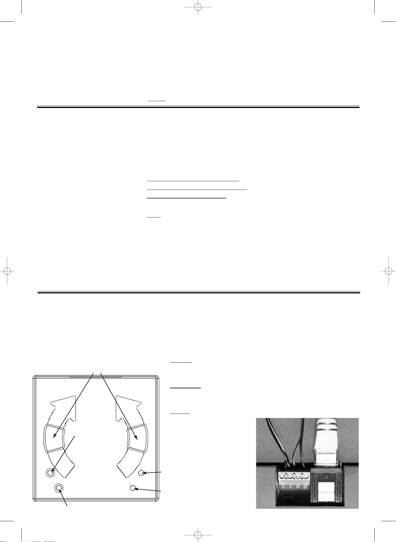
Wiring
Connection points are marked
on the underside as follows:
B1 and B2
= connect to rail
power supply; powers bridge
rails.
U &
V = connect to AC terminals on power pack; powers
drive mechanism.
All wires are secured using the
small screw terminals.
Plug in the large gray cable
from the indexing unit (located
beneath the pit) into the port
on the side of the control box.
933-2829 I sheet 12/2/04 10:23AM Page 2
 Loading...