

WWAALLTTHHEERR PPIILLOOTT
Betriebsanleitung / Operating Instructions / Instruccciones de
Servicio
Automatische Spritzpistolen / Automatic Spray Guns / Pistola
de Pulverización
PILOT WA 600 / WA 610
The WALTHER PILOT Product Range
• Manual spray guns
• Automatic spray guns
• HVLP spray guns
• Two-component spray guns
• Pressure containers
• Nonpressurized containers
• Agitator systems
• Airless equipment and fluid pumps
• Material circulation systems
• Two-pack systems
• Marking equipment
• Combined spraying and drying booths
• Spray booths with dry filtering
• Spray booths with wet filtering
• Powder booths
• Powder spraying equipment
• Adhesive spraying systems
• Dryers
• Air regulators / air filters
• Health protection equipment
Das WALTHER PILOT - Programm
• Hand-Spritzpistolen
• Automatik-Spritzpistolen
• Niederdruck-Spritzpistolen (System HVLP)
• Zweikomponenten-Spritzpistolen
• Materialdruckbehälter
• Drucklose Behälter
• Rührwerk-Syisteme
• Airless-Geräte und Flüssigkeitspumpen
• Materialumlaufsysteme
• 2-K - Anlagen
• Signieranlagen
• Kombinierte Spritz- und Trockenboxen
• Absaugsysteme mit Trockenabscheidung
• Absaugsysteme mit Nassabscheidung
• Pulversprühstände
• Pulverspritzgeräte
• Kleberspritzsysteme
• Trockner
• Zuluft-Systeme
• Atemschutz-Systeme und Zubehör
WALTHER Spritz- und Lackiersysteme GmbH
Kärntner Str. 18-30 • D-42327 Wuppertal
Tel.: 0202 / 787-0 • Fax: 0202 / 787-217
http://www.walther-pilot.de
E-mail: info@walther-pilot.de
PILOT WA 600 / WA 610
Rep.-Set Nr.:
Repair Set No.:
Núm. kit de reparación: V 16 600 02 .. 3
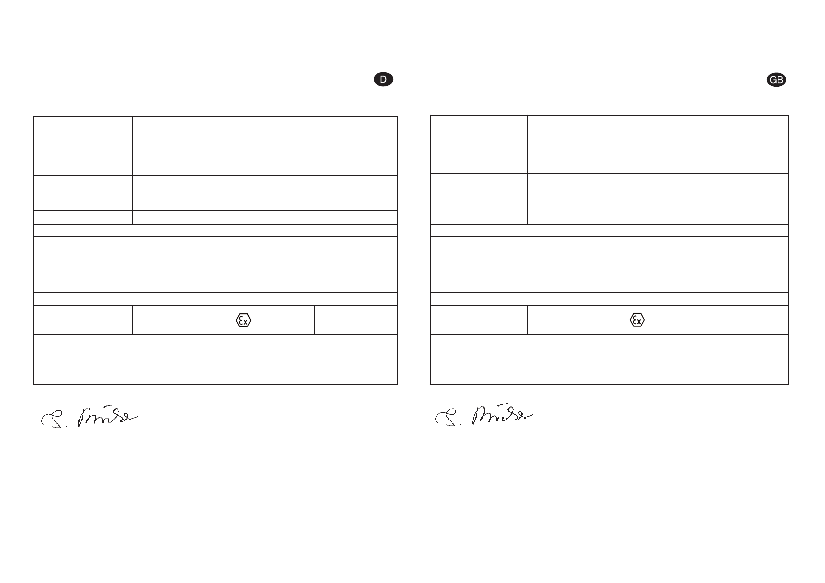
EG-Konformitätserklärung
Wir, der Gerätehersteller, erklären in alleiniger Verantwortung, daß das Produkt in
der untenstehenden Beschreibung den einschlägigen grundlegenden Sicherheitsund Gesundheitsanforderungen entspricht.Bei einer nicht mit uns abgestimmten
Änderung an dem Gerät oder bei einer unsachgemäßen Verwendung verliert diese
Erklärung ihre Gültigkeit.
Wuppertal,den 7. Juli 2003
Name:Torsten Bröker
Stellung im Betrieb:Leiter der Konstruktion und Entwicklung
Diese Erklärung ist keine Zusicherung von Eigenschaften im Sinne der Produkthaftung. Die Sicherheitshinweise der
Produktdokumentation sind zu beachten.
Declaration of CE-Conformity
We, the manufacturers of the equipment, hereby declare under our sole responsibility that the product(s) described below conform to the essential safety requirements. This declaration will be rendered invalid if any changes are made to the
equipment without prior consultation with us.
Wuppertal, the 7th of July 2003
Name:Torsten Bröker
Position:Manager, Design and Development
This Declaration does not give assurance of properties in the sense of product liability.The safety instructions provided in the product documentaion must be observed at all times.
Hersteller WALTHER Spritz-und Lackiersysteme GmbH
Kärntner Str. 18-30
D-42327 Wuppertal
Tel.: 0202 / 787-0
Fax: 0202 / 787-217 • www.walther-pilot.de
Typenbezeichnung Modell: Automatische Spritzpistole PILOT WA 600 / WA 610
WA 600 V 20 410
WA 610 V 20 420
Verwendungszweck Verarbeitung spritzbarer Materialien
Angewandte Normen und Richtlinien
EG-Maschinenrichtlinien 98 / 37 EG
94 / 9 EG (ATEX Richtlinien)
DIN EN 292 Teil 1
DIN EN 292 Teil 2
DIN EN 1953
Spezifikation im Sinne der Richtlinie 94 / 9 / EG
Kategorie 2 Gerätebezeichnung II 2 G c T 5
Tech.File,Ref.:
2406
besondere Hinweise :
Das Produkt ist zum Einbau in ein anderes Gerät bestimmt. Die Inbetriebnahme ist so
lange untersagt, bis die Konformität des Endproduktes mit der Richtlinie 98 / 9 / EG festgestellt ist.
Manufacturer WALTHER Spritz-und Lackiersysteme GmbH
Kärntner Str. 18-30
D-42327 Wuppertal
Tel.: 0202 / 787-0
Fax: 0202 / 787-217 • www.walther-pilot.de
Type Designation Model: Automatic Spray Gun PILOT WA 600 / WA 610
WA 600 V 20 410
WA 610 V 20 420
Intended purpose Processing of sprayable media
Applied Standards and Directives
EU-Machinery Directive 98 / 37 CE
94 / 9 EC (ATEX Directives)
DIN EN 292 Part 1
DIN EN 292 Part 2
DIN EN 1953
Specification according 94 / 9 / CE
Category 2 Part marking II 2 G c T 5
Tech.File,Ref.:
2406
special remarks :
The named product is intended for installation in other equipment.Commissioning is prohibited until such time as the end product has been proved to conform to the provision of
the Directives 98 / 37 / CE.
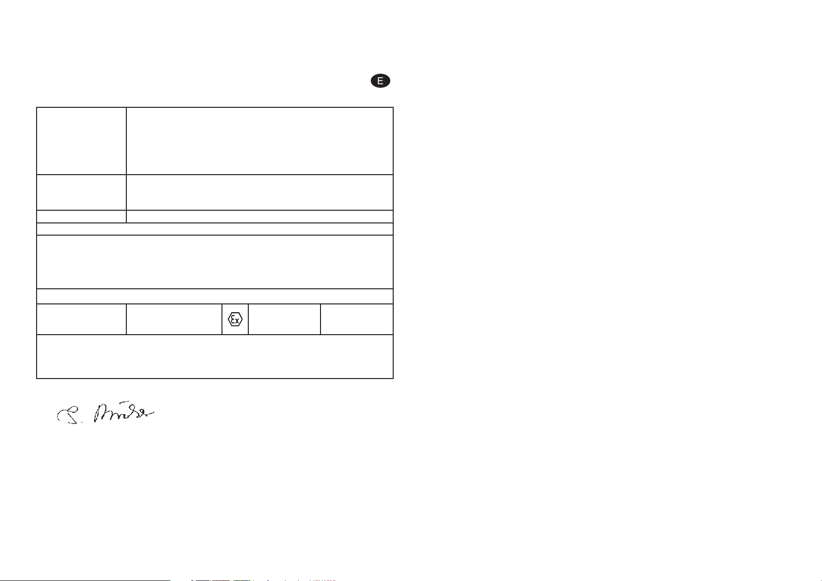
Declaración de conformidad CE
Como fabricante de este aparato, certificamos bajo nuestra plena responsabilidad
que el producto descrito más abajo cumple con los requisitos de seguridad y
protección de la salud en vigor. Cualquier modificación sin autorización previa o
uso inadecuado del aparato anulan la validez de esta declaración.
Wuppertal, el 7 de julio 2003
Nombre: Torsten Bröker
Puesto: Jefe de la construcción y del desarrollo
Esta declaración no constituye una declaración de responsabilidad en cuanto a la caracteristicas estipuladas en la
garantía del aparato. Las consignas de seguridad de las instrucciones de uso deben seguirse.
i.V.
Fabricante WALTHER Spritz-und Lackiersysteme GmbH
Kärntner Str. 18-30
D-42327 Wuppertal
Tel.: 0202 / 787-0
Fax: 0202 / 787-217
www.walther-pilot.de • Email: info@walther-pilot.de
Denominación del
modelo
Pistolas automáticas de pulverización PILOT WA 600 / WA 610
WA 600 V 20 410
WA 610 V 20 420
(Versión circulación)
Uso aplicación de materiales pulverizables
Normas y directivas aplicadas
Directiva EU sobre las máquinas 98 / 37 CE
94 / 9 EC (directivas ATEX)
DIN EN 292 1a Parte
DIN EN 292 2da Parte
DIN EN 1953
Especificación en el sentido de 94 / 9 / CE
Categoría 2
designación del aparato
II 2 G c T 5
Tech.File,Ref.:
2406
Indicaciones particulares:
Este aparato está diseñado para integrarse a otro equipo. La puesta en marcha no se
autoriza hasta que la conformidad del producto final con los requisitos de la directiva
98 / 37 / CE no haya sido establecida.

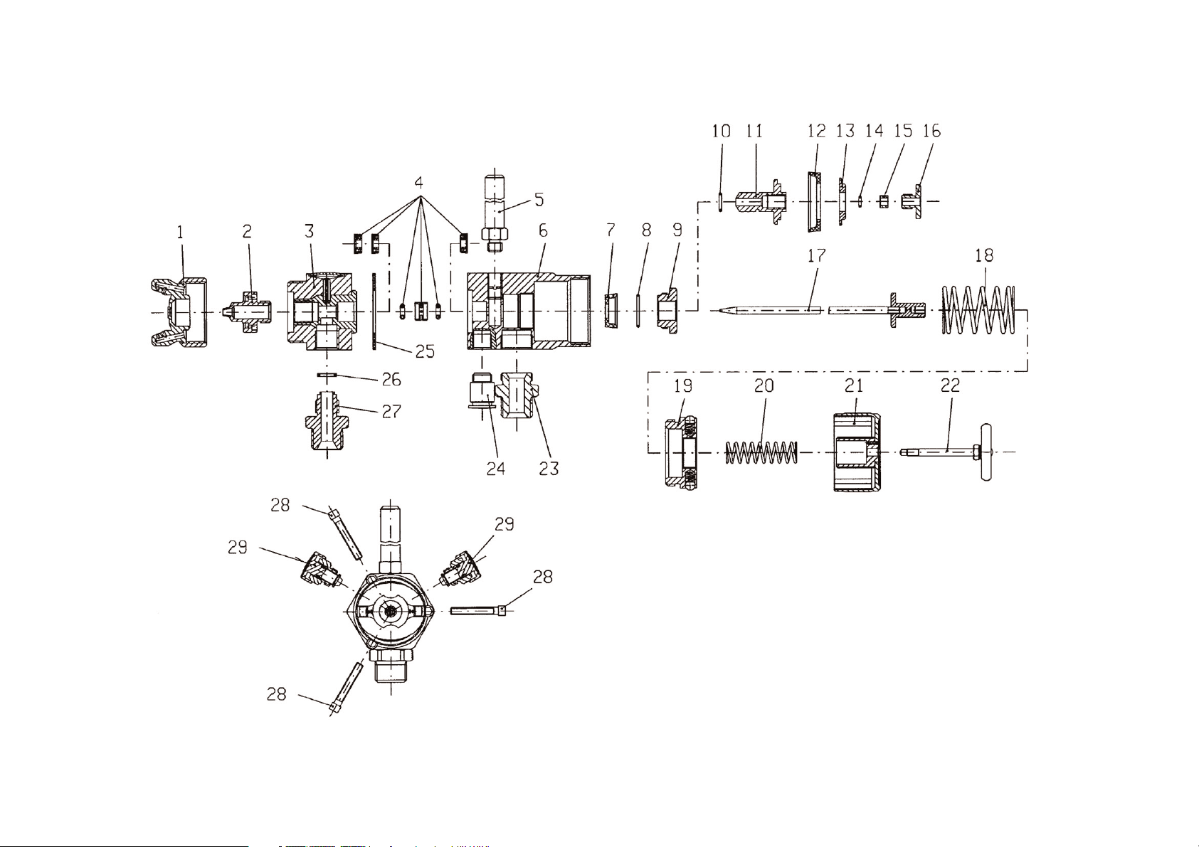
Ersatzteilliste WA 600 und WA 610
Pos. Ersatzteilnummer Bezeichnung
1 V 10 151 30 039* Luftkopf 0,3 - 1,5 mm Ø
V 10 151 30 189* Luftkopf 1,8 - 2,2 mm Ø
2 V 10 151 40 .. 3* Materialdüse
3 V 20 410 10 000 Vorderteil
4 V 09 001 80 000 Nadelpackung kompl.
5 V 20 310 09 003 Befestigungsbolzen
6 V 20 410 40 000 Kolbengehäuse
7 V 09 220 27 000 Topfmanschette
8 V 09 103 22 001 O-Ring
9 V 20 410 24 004 Kolbenbuchse
10 V 09 102 67 000 O-Ring
11 V 20 410 23 004 Kolben
12 V 09 220 28 000 Topfmanschette
13 V 20 410 18 004 Klemmscheibe
14 V 09 102 20 001 O-Ring
15 V 20 410 39 004 Druckstück
16 V 20 410 16 004 Kolbenschraube
17 V 20 410 30 .. 3* Materialnadel
18 V 20 410 17 000 Kolbenfeder
19 V 20 410 27 000 Gewindebuchse
20 V 20 410 28 003 Nadelfeder
21 V 20 410 29 000 Regelkappe
22 V 20 410 36 000 Zugstange kompl.
23 V 20 410 19 005 Spritzluftanschluss
24 V 66 101 53 322 Steuerluftanschluss
25 V 09 001 81 000 Dichtung
26 V 09 002 51 000 Dichtung
27 V 20 410 13 003 Materialanschluß
28 V 20 410 37 003 Innensechskantschraube
29 V 20 410 20 000 Rund- u. Breitstrahlregelung
Abweichende Ersatzteile Modell WA 610
3 V 20 420 10 000 Vorderteil
• Bei Ersatzteilbestellung bitte entsprechende Größe angeben,
Durchmesser: 0,3 • 0,5 • 0,8 • 1,0 • 1,2 • 1,5 • 1,8 • 2,0 • 2,2 mm
Wir empfehlen, alle fett gedruckten Teile (Verschleissteile) am Lager zu halten.
Rep.-Set Nr.: V 16 600 02 .. 3
beinhaltet alle fett gedruckten Ersatzteile
Inhaltsverzeichnis
1 Allgemeines
1.1 Kennzeichnung der Modelle
1.2 Bestimmungsmäßige Verwendung
1.3 Sachwidrige Verwendung
2 Technische Beschreibung
3 Sicherheitshinweise
4 Inbetriebnahme
4.1 Steuerluft-, Zerstäuberluft- und Materialanschluss
4.2 Spritzbildprobe erzeugen
4.3 Spritzbild verändern
4.4 Mängel eines Spritzbildes beheben
5 Spritzautomat umrüsten
5.1 Luftkopf wechseln
5.2 Materialdüse wechseln
5.3 Materialnadel wechseln
5.4 Nadelpackung wechseln
6 Fehlersuche und -beseitigung
7 Reinigung und Wartung
8 Technische Daten

1 Allgemeines
1.1 Kennzeichnung der Modelle
Modelle: Automatische Spritzpistole PILOT WA 600 / WA 610
Typ: WA 600 V 20 600
WA 610 V 20 610
Hersteller: WALTHER Spritz-und Lackiersysteme GmbH
Kärntner Str. 18-30
D-42327 Wuppertal
Tel.: 0202 / 787-0
Fax: 0202 / 787-217 • www.walther-pilot.de
1.2 Bestimmungsgemäße Verwendung
Der automatische Spritzautomat dient ausschließlich der Verarbeitung spritzbarer
Medien, insbesondere:
• Lacke und Farben
• Fette, Öle und Korrosionsschutzmittel
• Kleber
• Keramikglasuren
• Beizen
Sind Materialien, die Sie verspritzen wollen, hier nicht aufgeführt, wenden Sie sich bitte
an WALTHER Spritz- und Lackiersysteme GmbH, Wuppertal.
Die spritzbaren Materialien dürfen lediglich auf Werkstücke bzw. Gegenstände aufgetragen werden.
Die Temperatur des Spritzmaterials darf 80°C nicht überschreiten.
Die Spritzautomaten PILOT WA 600 und WA 610 sind keine handgeführten
Spritzautomaten und müssen deshalb an einer geeigneten Halterung befestigt werden.
Die bestimmungsmäßige Verwendung schließt auch ein, dass alle Hinweise und
Angaben der vorliegenden Betriebsanleitung gelesen, verstanden und beachtet werden.
Das Gerät erfüllt die Explosionsschutz-Forderungen der Richtlinie 94/9EG (ATEX100a)
für die auf dem Typenschild angegebene Explosionsgruppe, Gerätekategorie, und
Temperaturklasse.
Beim Betreiben des Gerätes sind die Vorgaben dieser Betriebsanleitung unbedingt einzuhalten.
Die vorgeschriebenen Inspektions- und Wartungsintervalle sind einzuhalten.
Die Angaben auf den Geräteschildern bzw. die Angaben in dem Kapitel technische
Daten sind unbedingt einzuhalten und dürfen nicht überschritten werden. Eine Überlastung des Gerätes muss ausgeschlossen sein.
Das Gerät darf in explosionsgefährdeten Bereichen nur nach Maßgabe der zuständigen
Aufsichtsbehörde eingesetzt werden.
Der zuständigen Aufsichtsbehörde bzw. dem Betreiber obliegt die Festlegung der
Explosionsgefährdung (Zoneneinteilung).
Es ist betreiberseitig zu prüfen und sicherzustellen, daß alle technischen Daten und
die Kennzeichnung gemäß ATEX mit den notwendigen Vorgaben übereinstimmen.
Anwendungen, bei denen der Ausfall des Gerätes zu einer Personengefährdung führen könnten, sind betreiberseitig entsprechende Sicherheitsmaßnahmen vorzusehen.
Falls im Betrieb Auffälligkeiten erkannt werden, muss das Gerät sofort stillgesetzt
werden und es ist mit WALTHER-PILOT Rücksprache zu halten.
Erdung / Potentialausgleich
Es muß sichergestellt werden, dass die Spritzpistole separat oder in Verbindung mit
dem Gerät auf dem sie aufgebaut ist, ausreichend geerdet ist (maximaler Widerstand
10
6
Ω).
1.3 Sachwidrige Verwendung
Der Spritzautomat darf nicht anders verwendet werden, als es im Abschnitt 1.2
Bestimmungsgemäße Verwendung beschrieben steht. Jede andere Verwendung
ist sachwidrig.
Zur sachwidrigen Verwendung gehören z. B.:
• Das Verspritzen von Materialien auf Personen und Tiere
• Das Verspritzen von flüssigem Stickstoff
2 Technische Beschreibung
Die Spritzautomaten PILOT WA 600 und WA 610 arbeiten voll automatisch und
werden über eine 3/2-Wege-Steuerventil angesteuert. Dazu können Hand-, Fußoder Magnetventile eingesetzt werden.
Zunächst wird die Zerstäuberluft über ein 3/2-Wege-Ventil zugeschaltet.
Danach wird das für die Steuerluft erforderliche 3/2-Wege-Ventil angesteuert. Die
in den Zylinderraum einströmende Druckluft betätigt den Steuerkolben und öffnet
die Materialzufuhr.
Wird die Steuerluft durch das 3/2-Wege-Ventil unterbrochen, entweicht die im
Zylinderraum befindliche Druckluft. Der Federdruck der Kolbenfeder verschließt die
Materialzufuhr zur Materialdüse.
Anschließend wird die Zerstäuberluft über das 3/2-Wege-Ventil abgeschaltet.
Die Materialnadel und die Materialdüse sind aus Edelstahl rostfrei gefertigt.
Sämtliche materialführenden Teile sind in Edelstahl rostfrei gefertigt.
3 Sicherheitshinweise
• Das Spritzgerät darf nur von sachkundigen Personen in Betrieb genommen werden.
• Die einschlägigen Sicherheits- und Arbeitsschutzvorschriften des jeweiligen
Landes oder Verwendungsgebietes sind zu beachten und einzuhalten.
• Beachten Sie die Verarbeitungs- und Sicherheitshinweise der Hersteller von
Spritzmaterial und Reinigungsmittel.
• Benutzen Sie das Spritzgerät nur in gut belüfteten Räumen. Im Arbeitsbereich ist
Feuer, offenes Licht und Rauchen verboten.
2
3
• Tragen Sie vorschriftsmäßigen Atemschutz, vorschriftsmäßige Arbeitskleidung und
einen Gehörschutz.
• Die partikelführende Abluft ist vom Arbeitsbereich und Betriebspersonal fern zu halten.
Sorgen Sie für eine entsprechende Absaugung.
• Halten Sie beim Verspritzen von Materialien keine Hände oder andere Körperteile vor
die unter Druck stehende Düse des Spritzgerätes.
• Richten Sie das Spritzgerät nicht auf Personen oder Tiere.
• Schalten Sie vor jeder Wartung und Instandsetzung die Luft- und Materialzufuhr
zum Spritzgerät drucklos.
• Es muß sichergestellt werden, dass die Spritzpistole separat oder in Verbindung mit dem
Gerät auf dem sie aufgebaut ist, ausreichend geerdet ist (maximaler Widerstand 10
6
Ω).
• Achten Sie darauf, daß nach Montage- und Wartungsarbeiten alle Muttern, Schrauben
und Verschraubungen fest angezogen sind.
• Verwenden Sie nur Original-Ersatzteile, da WALTHER nur für diese eine sichere und
einwandfreie Funktion garantieren kann.
Bei Nachfragen zur gefahrlosen Benutzung der Spritzgeräte wenden Sie sich bitte an
WALTHER Spritz- und Lackiersysteme GmbH, D-42327 Wuppertal.
4 Inbetriebnahme
Bevor Sie den Spritzautomaten in Betrieb setzen, müssen folgende Voraussetzungen
erfüllt sein:
• Der Steuerluftdruck muss an dem Spritzautomaten anstehen.
• Der Zerstäuberluftdruck muss an dem Spritzautomaten anstehen.
• Der Materialdruck muss an dem Spritzautomaten anstehen.
4.1 Steuerluft-, Zerstäuberluft- und Materialanschluß
• Befestigen Sie den Steuerluftanschluß (über das 3/2-Wege-Ventil) an dem Spritzauto-
maten und stellen Sie den erforderlichen Steuerluftdruck ein (min. 4,5 bar).
• Befestigen Sie den Zerstäuberluftanschluß an der Luftleitung (gereinigte Druckluft) und
an dem Zerstäuberluftanschluß des Spritzautomaten.
1 2 3
1 2 3
1 = Materialanschluß 2 = Steuerluftanschluß 3 = Zerstäuberluftanschluß
• Schalten Sie die Druckluft ein und stellen Sie am Reduzierventil den gewünschten Zerstäuberluftdruck ein (max. 8 bar).
• Füllen Sie Material in das Materialdruckgefäß ein und verschließen Sie den Deckel.
• Befestigen Sie den Materialzuführungsschlauch am Materialdruckgefäß bzw.
einer Pumpenanlage und am Materialanschluß des Spritzautomaten. Stellen Sie
den gewünschten Materialdruck ein (max. 8 bar).
• Öffnen Sie den Materialhahn am Druckgefäß.
4.2 Spritzbildprobe erzeugen
Eine Spritzbildprobe sollte immer dann erstellt werden, wenn:
• der Spritzautomat zum ersten Mal in Betrieb gesetzt wird.
• das Spritzmaterial ausgetauscht wird.
• der Spritzautomat zur Wartung oder Instandhaltung zerlegt wurde.
Das Spritzbild kann auf ein Probewerkstück, Blech, Pappe oder Papier appliziert
werden.
4.3 Spritzbild verändern
• Zur Auswahl stehen Rund- oder Breitstrahlköpfe.
• Durch Verändern der Zerstäuberluft wird die Strahlbreite variiert.
• Die Materialdurchflußmenge wird durch den Materialdruck und dem Durchmesser
der Materialdüse bestimmt.
4.4 Mängel eines Spritzbildes beheben
Die folgende Tabelle zeigt Ihnen, mit welchen Einstellungen Sie das Spritzbild
beeinflussen können.
angestrebtes Spritzergebnis
54
Spritzbildprobe Abweichung erforderliche Einstellung
Spritzbild ist in der Mitte
zu dick
• breitere Spritzstrahlform
einstellen
Spritzbild ist an den
Enden zu dick
• rundere Spritzstrahlform
einstellen
Spritzbild ist ziemlich
grobtropfig
• Zerstäuberluftdruck
erhöhen
Materialauftrag ist in der
Spritzbildmitte sehr dünn
• Zerstäuberluftdruck
verringern
Spritzbild ist in der Mitte
gespalten
• Düsendurchmesser erhöhen
• Zerstäuberluftdruck verringern
• Materialdruck erhöhen
Spritzbild ist sehr ballig
• Materialdruck verringern
• Zerstäuberluftdruck erhöhen

6 Fehlersuche und -beseitigung
Warnung
Schalten Sie vor jeder Instandsetzung die Steuer- und Zerstäuberluft sowie die
Materialzufuhr zur Spritzpistole drucklos - Verletzungsgefahr.
7 Reinigung und Wartung
• Damit die Lebensdauer und Funktion des Spritzautomaten lange erhalten bleibt,
muss der Spritzautomat regelmäßig gewartet, gereinigt und geschmiert werden.
• Schalten Sie vor jeder Wartung die Steuer- und Zerstäuberluft sowie die Materialzufuhr zu dem Spritzautomaten drucklos.
• Die Reinigung sollte nach jedem Farb- und Materialwechsel oder je nach Verschmutzungsgrad erfolgen.
• Verwenden Sie zur Reinigung nur Reinigungsmittel, die vom Hersteller des
Spritzmaterials angegeben werden und die folgenden Bestandteile nicht enthalten:
- Halogenierte Kohlenwasserstoffe
(z. B. 1.1.1 Trichlorethan, Methylen-Chlorid, usw.)
-Säuren und säurehaltige Reinigungsmittel
-Entlackungsmittel
-Regenerierte Lösemittel (Reinigungsverdünnungen)
• Legen Sie den Spritzautomaten nie komplett in Löse- oder Reinigungsmittel. Die
einwandfreie Funktion des Spritzautomaten könnte sonst gefährdet sein.
• Verwenden Sie zur Reinigung keine spitzen oder harten Gegenstände.
Präzisionsteile könnten sonst beschädigt werden und das Spritzergebnis verschlechtern.
Fehler Ursache Abhilfe
Pistole tropft Materialnadel oder -düse
verschmutzt
Materialnadel oder -düse
beschädigt
Ausbauen und reinigen
Austauschen
Pistole öffnet nicht Steuerluftdruck zu niedrig Steuerluftdruck erhöhen auf min.
4,5 bar
Stoßweiser oder
flatternder
Spritzstrahl
Zu wenig Material im
Spritzbehälter
Material auffüllen (s. Betriebsanleitung des Materialherstellers)
Pistole bläst in
Ruhestellung
Topfmanschette Pos. 7
beschädigt
Auswechseln
Material sprudelt im
Materialbehälter
Zerstäuberluft gelangt
über Materialkanal in den
Materialbehälter.
Materialdüse oder Luftkopf
nicht richtig angezogen
Teile reinigen, anziehen oder
ersetzen
Spritzteil einseitig Hornbohrung am Luftkopf
verschmutzt
Ausbauen und reinigen
l
l
5 Spritzautomat umrüsten
Die zum Spritzmaterial passende Luftkopf-, Materialdüse-, Nadelkombination bildet eine
aufeinander abgestimmte Einheit - die Düseneinlage.Tauschen Sie immer die komplette
Düseneinlage aus, damit die gewünschte Spritzbildqualität erhalten bleibt.
Warnung
Unterbrechen Sie vor jeder Umrüstung die Luft- und Materialzufuhr zur Spritzpistole Verletzungsgefahr.
Hinweis
Zur Durchführung der im Folgenden aufgeführten Arbeitsschritte benutzen Sie bitte die
Explosionszeichnung am Anfang dieser Betriebsanleitung.
5.1 Luftkopf wechseln
1. Schrauben Sie die Luftkopfmutter ab.
2. Entfernen Sie den Luftkopf Pos. 1.
5.2 Materialdüse wechseln
1. Schrauben Sie die Luftkopfmutter ab.
2. Entfernen Sie den Luftkopf.
3. Schrauben Sie die Materialdüse Pos. 2 aus.
4. Der Einbau geschieht in umgekehrter Reihenfolge.
5.3 Materialnadel wechseln
1. Schrauben Sie die Zugstange Pos. 22 aus.
2. Schrauben Sie die Regelkappe Pos. 21 ab.
3. Entfernen Sie die Nadelfeder Pos. 20.
4. Schrauben Sie die Gewindebuchse Pos. 19 aus dem Körper.
5. Ziehen Sie die komplette Einheit Pos. 9 -16, die Nadel Pos. 17 und den Kolben
Pos.11 heraus.
6. Ziehen Sie die Nadel aus dem Kolben heraus.
7. Das Einstellmaß, die Nadelspitze bis zum Kolben beträgt 79,0 mm.
8. Der Einbau geschieht in umgekehrter Reihenfolge.
5.4 Nadelpackung wechseln
1. Schrauben Sie das Vorderteil Pos. 3 vom Kolbengehäuse Pos. 6 ab.
2. Entfernen Sie die Dichtung Pos. 25.
3. Bauen Sie die komplette Nadelpackung Pos. 4 aus. Verwenden Sie hierzu einen
gebogenen Draht.
4. Fetten Sie die neue Nadelpackung leicht ein.
5. Der Einbau geschieht in umgekehrter Reihenfolge.
76

8
• Für Schäden, die aus einer unsachgemäßen Behandlung herrühren, übernimmt
WALTHER PILOT keine Gewährleistung.
8 Technische Daten
Gewicht: 360 g
Anschluß:
Zerstäuberluft: G 1/4
Steuerluft: CK 1/8 PK 4
Materialzufuhr: G 3/8
Druckbereich:
Steuerluftdruck: min. 4,5 bar
Materialdruck: max. 8 bar
Zerstäuberluftdruck: max. 8 bar
Schallpegel
(gemessen in
ca. 1 m Abstand
zur Spritzpistole) 83 dB (A)
Luftverbrauch bei:
Eingangsdruck: Rundstrahl Breitstrahl
1,0 bar 150 L/min. 180 L/min.
2,0 bar 210 L/min. 260 L/min.
3,0 bar 250 L/min. 310 L/min.
4,0 bar 280 L/min. 360 L/min.
5,0 bar 310 L/min. 400 L/min.
6,0 bar 340 L/min. 430 L/min.
Technische Änderungen vorbehalten.

Listing of Replacement Parts WA 600 and WA 610
Item Parts No. Description
1 V 10 151 30 039* Air Control Head 0,3 - 1,5 mm Ø
V 10 151 30 189* Air Control Head 1,8 - 2,2 mm Ø
2 V 10 151 40 .. 3* Material Nozzle
3 V 20 410 10 000 Front Part
4 V 09 001 80 000 Needle Packing compl.
5 V 20 310 09 003 Connection
6 V 20 410 40 000 Piston Casing
7 V 09 220 27 000 Cup Seal
8 V 09 103 22 001 O-Ring
9 V 20 410 24 004 Piston-Boss Bushing
10 V 09 102 67 000 O-Ring
11 V 20 410 23 004 Piston Bushing
12 V 09 220 28 000 Cup seal
13 V 20 410 18 004 Clamping Washer
14 V 09 102 20 001 O-Ring
15 V 20 410 39 004 Pressure Ring
16 V 20 410 16 004 Piston Screw
17 V 20 410 30 .. 3* Material Needle
18 V 20 410 17 000 Piston Spring
19 V 20 410 27 000 Threaded Ring
20 V 20 410 28 003 Needle Spring
21 V 20 410 29 000 Cap
22 V 20 410 36 000 Threaded Rod compl.
23 V 20 410 19 005 Atomizing Air Connection
24 V 66 101 53 322 Control Air Connection
25 V 09 001 81 000 Seal
26 V 09 002 51 000 Seal
27 V 20 410 13 003 Material Connection
28 V 20 410 37 003 Hexagonal Screw
29 V 20 410 20 000 Round- and Wide-Fan-Adjustment
Deviating spare parts Model WA 610
3 V 20 420 10 000 Front Part
* Please make sure to quote the required size when placing an order for replacement
parts,diameter: 0.3 • 0.5 • 0.8 • 1.0 • 1.2 • 1.5 • 1.8 • 2.0 • 2.2 mm
We recommend to hold all bold-faced replacement parts on stock.
Repair Set No.: V 16 600 02 .. 3
Includes all bold-faced wearing parts
Contents
1 General
1.1 Identification of Model Versions
1.2 Normal Use
1.3 Improper use
2 Technical Description
3 Safety
4 Using the Spray Gun
4.1 Connections for Control Air, Atomising Air and Material
4.2 Spraying a Test Pattern
4.3 Changing the Spray Pattern
4.4 Correction of Spray Pattern Imperfections
5 Re-tooling the Spray Gun
5.1 Changing the Air Cap
5.2 Changing the Material Nozzle
5.3 Changing the Material Needle
5.4 Changing the Needle Seal
6 Troubleshooting
7 Cleaning and Maintenance
8 Technical Data

1 General
1.1 Identification of Model Version
Model: Automatic Spray Gun PILOT WA 600 / WA 610
Type: WA 600 V 20 600
WA 610 V 20 610
Manufacturer: WALTHER Spritz- und Lackiersysteme GmbH
Kärntner Straße 18-30
D-42327 Wuppertal
Tel: +49 202 787-0
Fax: +49 202 787-217 • www.walther-pilot.de
1.2 Normal Use
The automatic spray gun must be used only for processing sprayable materials, in particular:
• lacquers and paints
• grease, oil and anti-corrosion agents
• adhesives, grease, oil and anti-corrosion agents
• ceramic glazes
• stains
If you intend to spray materials that are not listed here, please contact WALTHER
Spritz- und Lackiersysteme GmbH, Wuppertal.
The sprayable materials must be sprayed only on workpieces or objects.
The temperature of the material to be sprayed must not exceed 80°C.
The model PILOT WA 600 und WA 610 is not a hand-held spray gun and must therefore
be mounted in a suitable bracket.
Proper use of the spray gun also includes the fact that you have read, understood and
observed all information, advice and safety requirements presented in this instruction
manual.
This equipment complies with the explosion protection requirements of Directive 94 / 9 /
EC (ATEX 100a) for the explosion group, equipment category and temperature class
indicated on the type plate. When using the equipment, the requirements specified in
these Operating Instructions must be observed at all times.
The technical data indicated on the equipment rating plates and the specifications in the
chapter "Technical Data" must be complied with at all times and must not be exceeded.
An overloading of the equipment must be ruled out.
The equipment may be used in potentially explosive atmospheres only with the authorisation of the relevant supervisory authority.
The relevant supervisory authority or the operator of the equipment are responsible for determining the explosion hazard (zone classification).
The operator must check and ensure that all technical data and the marking of the
equipment in accordance with ATEX are compliant with the necessary requirements.
The operator must provide corresponding safety measures for all applications in
which the breakdown of the equipment might lead to danger to persons.
If any irregularities are observed while the equipment is in operation, the equipment must be put out of operation immediately and WALTHER PILOT must be
consulted.
Grounding / Equipotential Bonding
You must ensure that the spray gun is properly earthed (grounded) either separately or in connection with the equipment with which it is being used (maximum
resistance 10
6
Ω).
1.3 Improper Use
The spray gun must not be used in any other way than as described above in the
section 1.2 Normal Use.
Any other form of use is prohibited.
Improper use includes:
• spraying materials onto persons or animals
• spraying liquid nitrogen
2 Technical Description
The models PILOT WA 600 and WA 610 are operated automatically by compressed air and is controlled via 3/2-way control valves. Hand-operated, foot-operated
or solenoid-valve-operated valves can be used for this purpose.
First, the atomising air is introduced by a 3/2-way valve.
Then, the 3/2-way control valve required for the control air is actuated.
The compressed air flowing into the cylinder chamber moves the control piston
and opens the material feed.
If the control air is interrupted by the 3/2-way valve, the compressed air in the
cylinder chamber is allowed to escape. The spring pressure of the piston spring
shuts off the material feed to the material nozzle.
After this, the atomising air is switched off by the 3/2-way valve.
Nozzle and needle are made of corrosion-free stainless steel.
3 Safety
• The spray gun must be used only by trained and qualified persons.
• All relevant rules of safety and workers' safety regulations applicable in the coun-
try or area of use must be fully observed.
• Observe the instructions given by the manufacturers of the spraying material and
the cleaning agents with regard to safety and proper use.
• Use the spray gun only in well-ventilated rooms. Fire, naked flames and smoking
are prohibited within the working area.
2 3

• Always wear the regulation breathing masks, protective clothing and hearing protection
when using the spray gun.
• Exhaust air which contains particles must be kept away from the working area and
operating personnel. Make sure that adequate exhaust extraction is provided.
• When spraying materials, keep your hands and other parts of the body away from the
pressurised nozzle of the spray gun.
• Do not direct the spray gun at persons or animals.
• Before carrying out maintenance or servicing, ensure that the air and material feed to
the spray gun have been de-pressurised.
• You must ensure that the spray gun is properly earthed (grounded) either separately or
in connection with the equipment with which it is being used (maximum resistance
10
6
Ω).
• After carrying out assembly and maintenance work, ensure that all nuts, bolts and
screw connections have been fully tightened.
• Use only original spare parts, since WALTHER can only guarantee safe and fault-free
operation for original parts.
For further information on the safe use of spraying equipment, please contact WALT-
HER Spritz- und Lackiersysteme GmbH, Wuppertal.
4 Using the Spray Gun
Before using the spray gun, ensure that the following conditions apply:
• The control air pressure is applied to the spray gun
• The atomising air pressure is applied to the spray gun
• The material pressure is applied to the spray gun
4.1 Connections for Control Air, Atomising Air and Material
• Connect the control air connector (via the 3/2-way valve) to the spray gun and set the
control air pressure (min. 4.5 bar).
• Connect the atomising air connector to the air hose (filtered compressed air supply) and to the atomising air connection.
• Switch on the compressed air and set the required atomising air pressure at the
reducing valve (max. 8 bar).
• Fill the pressure pot with the material to be sprayed and close the lid.
• Connect the material feed hose to the pressure pot or the pump and to the
material connection. Set the required material pressure (max. 8 bar).
• Open the material valve on the pressure pot.
4.2 Spraying a Test Pattern
A test spray pattern should always be made whenever:
• the spray gun is used for the first time
• the spraying material is changed
• the spray gun has been disassembled for maintenance or servicing.
The test pattern can be sprayed on a test workpiece, panel, cardboard or paper.
4.3 Changing the Spray Pattern
• Round-fan or wide-fan air caps are available.
• The fan width can be varied by changing the atomising air.
• The material flow rate is determined by the material pressure and the diameter
of the material nozzle.
4.4 Correction of Spray Pattern Imperfections
The following table shows how to correct a defective spray pattern.
Desired Spray Pattern
1 2 3
1 2 3
1 = Material connection 2 = Control air connection 3 = Atomizing air connection
54
Spray pattern test Fault Necessary adjustment
Swollen centre • Spray jet should be flatter
Swollen ends • Spray jet should be rounder
Coarse pearl effect • Increase atomising air pressure
Unduly thin paint
layer in centre
• Decrease atomising air pressure
Split centre
• Increase nozzle diameter
• Reduce atomising air pressure
• Increase material pressure
Split centre
• Decrease material pressure
• Increase atomising air pressure

5 Re-tooling the Spray Gun
The combination of air cap, material nozzle and needle for a certain spraying material
forms a specially matched unit - the nozzle assembly.
Always exchange the complete nozzle assembly in order to maintain the desired spray
pattern quality.
Warning
Air and material inputs must be shut off prior to re-tooling - risk of injury.
Note
Please refer to the exploded view at the beginning of this manual to perform the steps
detailed below.
5.1 Changing the Air Cap
1.Unscrew the air cap nut.
2.Remove the air cap.
5.2 Changing the Material Nozzle
1.Unscrew the air cap nut.
2.Remove the air cap.
3.Unscrew the material nozzle from the spray gun head.
4.Installation takes place in reverse order.
5.3 Changing the Material Needle
1.Unscrew the threaded rod.
2.Unscrew the air cap.
3.Remove the needle spring.
4.Unscrew the threaded ring.
5.Withdraw the piston together with the material needle.
6.Unscrew the material needle from the piston.
7.The distance between the tip of the material needle and the piston should be set at
79,0 mm.
8.Installation takes place in reverse order.
5.4 Changing the Needle Seal
1.Unscrew the front part from the piston casing.
2.Remove the seal.
3.Remove the complete needle packing using a strong wire with a hook at its end.
4.Lubricate the new needle seal packing..
5.Installation takes place in reverse order.
6 Troubleshooting
Warning
Prior to any servicing and repair work the spray gun should be inunpressurised
state, i.e. all control air and atomising air pressure as well as all material inputs
must be shut off - risk of injury.
7 Cleaning and maintenance
• To ensure that the spray gun functions properly and to maximise its service life,
the spray gun must be maintained, cleaned and lubricated regularly.
• Before carrying out any maintenance, ensure that the control air and atomising
air as well as the material feed are de-pressurised.
• Cleaning should be carried out after every colour and material change or according to the degree of contamination.
• For cleaning the spray gun, use only those cleaning agents that are specified by
the material manufacturer and ensure that they do not contain any of the following components:
-halogenated hydrocarbons,( e.g. 1,1,1-trichloroethane, methylene chloride,etc.)
-acids or acidic cleaning agents,
-paint strippers,
-regenerated solvents (cleaning thinners).
• Never immerse the whole spray gun in solvent or cleaning agent, as this could
harm the correct functioning of the gun.
Spray pattern Fault Adjustment
Gun drips Material needle or nozzle
dirty
Material needle or nozzle
damaged
Remove and clean
Replace
Gun does not open Control air pressure too low Increase control air pressu-
re to min. 4.5 bar
Irregular or splattering
spray
Insufficient material in container
Fill up with material (see
instructions from material
manufacturer)
Gun sprays when switched off
O-ring Item 7 damaged Replace
Material bubbling in
material container
Atomising air is entering the
material container via the
material channel. Material
nozzle or air cap not properly tightened
Clean the parts, tighten or
replace
Spray fan one-sided Air cap horn bore dirty Remove and clean
6 7
l
l

• Do not use sharp or hard objects to clean the spray gun, as this might cause
damage to precision parts and impair the spraying result.
• WALTHER PILOT cannot accept any liability for damage caused by improper
treatment of the spray gun.
8 Technical Data
Weight: 360 g
Connections
Atomising air: G 1/4
Control air CK 1/8 PK 4
Material feed: G 3/8
Pressure range:
Control air pressure: min. 4,5 bar
Material pressure: max. 8 bar
Atomising air pressure: max. 8 bar
Noise Level
(measured at a
distance of ca. 1 m
from spray gun) 83 dB (A)
Air Consumption:
Air input: Round fan Wide fan
1,0 bar 150 L/min. 180 L/min.
2,0 bar 210 L/min. 260 L/min.
3,0 bar 250 L/min. 310 L/min.
4,0 bar 280 L/min. 360 L/min.
5,0 bar 310 L/min. 400 L/min.
6,0 bar 340 L/min. 430 L/min.
Technical data are subject to change.
8

Lista de partes de recambio PILOT WA 600 y WA 610
Pos. Referencia Denominación
1 V 10 151 30 039* Cabeza neumática 0,3 - 1,5 mm ø
V 10 151 30 189* Cabeza neumática 1,8 - 2,2 mm ø
2 V 10 151 40 .. 3* Tobera de material
3 V 20 410 10 000 Parte anterior
4 V 09 001 80 000 Empaquetadura de aguja compl.
5 V 20 310 09 003 Bulón de fijación
6 V 20 410 40 000 Caja de pistón
7 V 09 220 27 000 Manguito
8 V 09 103 22 001 Junta tórica
9 V 20 410 24 004 Casquillo de pistón
10 V 09 102 67 000 Junta tórica
11 V 20 410 23 004 Pistón
12 V 09 220 28 000 Manguito
13 V 20 410 18 004 Arandela
14 V 09 102 20 001 Junta tórica
15 V 20 410 39 004 Pieza de presión
16 V 20 410 16 004 Tornillo de pistón
17 V 20 410 30 .. 3* Aguja de material
18 V 20 410 17 000 Resorte de pistón
19 V 20 410 27 000 Casquillo roscado
20 V 20 410 28 003 Resorte de aguja
21 V 20 410 29 000 Tapa
22 V 20 410 36 000 Barra de tracción compl.
23 V 20 410 19 005 Empalme de aire de pulverización
24 V 66 101 53 322 Empalme de aire de mando
25 V 09 001 81 000 Junta
26 V 09 002 51 000 Junta
27 V 20 410 13 003 Empalme de material
28 V 20 410 37 003 Tornillo con hueco hexagonal en la cabeza
29 V 20 410 20 000 Regulación de chorro redondo y ancho
Lista de partes de recambio para modelo PILOT WA 610 (parte divergente)
3 V 20 420 10 000 Parte anterior
* Al encargarnos piezas de recambio indíquenos siempre los respectivos tamaños.
Recomendamos mantener siempre un stock de las partes de desgaste señalados en
negrita.
Tamaño de tobera a escoger: 0,3 • 0,5 • 0,8 • 1,0 • 1,2 • 1,5 • 1,8 • 2,0 • 2,2 mm
Kit de reparación: V 16 600 02 .. 3
contiene todas las partes de desgaste (señalados en negrita).
Sumario
1 Generalidades
1.1 Identificación de los modelos
1.2 Uso común
1.3 Uso indebido
2 Características técnicas
3 Consignas generales de seguridad
4 Montaje
4.1 Fijación de la pistola
4.2 Empalmes de alimentación
5 Manejo
5.1 Consignas de seguridad
5.2 Puesta en y fuera de servicio
5.3 Prueba de aplicación
5.4 Regulación del chorro de pulverización
5.5 Eliminar los defectos de la prueba de aplicación
5.6 Modificación del chorro de pulverización
6 Limpieza
6.1 Consignas de seguridad
6.2 Limpieza completa
6.3 Limpieza de rutina
7 Mantenimiento
7.1 Recambio de empaquetadura de aguja defectosa
7.2 Recambio de tobera, aguja, resortes y juntas
8 Identificación y eliminación de los fallos
9 Fluidos residuales
10 Datos técnicos

11 Generalidades
1.1 Identificación de los modelos
Modelos: Pistolas automáticas de pulverización PILOT WA 600 / WA 610
Tipo: WA 600 V 20 410
WA 610 V 20 420
(Versión circulación)
Fabricante: WALTHER Spritz-und Lackiersysteme GmbH
Kärntner Str. 18-30
D-42327 Wuppertal
Tel.: 00 49 202 / 787-0
Fax: 00 49 202 / 787-217
www.walther-pilot.de • Email: info@walther-pilot.de
1.2 Uso común
Las pistolas automáticas de pulverización PILOT WA 600 / WA 610 se prestan a la
aplicación de toda clase de materiales pulverizables, como por ejemplo:
• lacas y pinturas
• grasas, aceites y anticorrosivos
• adhesivos
• barnizes ceramicos
• fluidos ácidos o
• agresivos
Si la presente lista no incluye los materiales que Ud. utiliza, consulte a WALTHER
Spritz- und Lackiersysteme GmbH, Wuppertal, Alemania.
El material sólo se puede aplicar sobre objetos o piezas.
La temperatura del producto pulverizado no debe exceder los 80°C.
Los modelos PILOT WA 600 / WA 610 no son pistolas manuales y por lo tanto se
tendrán que colocar sobre un soporte estable y adecuado.
El termino "uso común" presupone que todas las consignas e instrucciones de servicio hayan sido leidas, entendidas y seguidas.
Este aparato cumple con los requisitos de protección contra las explosiones de la
directiva 94 / 9 CE (ATEX100a) para el grupo, la categoría y la clase de temperatura
en la placa de características. Es indispensable respetar las indicaciones de estas
instrucciones de servicio. Siga los intervalos de mantenimiento y revisión prescritos.
Siga cuidadosamente las indicaciones de las placas de características y del capitulo
Datos técnicos. Hay que evitar absolutamente una sobrecarga del aparato. El aparato solo deberá utilizarse conforme a las instrucciones de las autoridades competentes.
La determinación del peligro de explosión incumbe a las autoridades competentes o al usuario (clasificación de las zonas).
El usuario debe asegurarse que los datos técnicos corresponden exactamente a los
requisitos ATEX. El usuario deberá tomar las medidas de seguridad necesarias en el
caso de aplicaciones susceptibles de representar un peligro para las personas.
Si se constatan disfuncionamientos del aparato, ponga inmediatamente el aparato
fuera de servicio y avise a WALTHER-PILOT.
Puesta a la tierra / compensación de potencial
Asegúrese que la pistola de pulverización, independiente o conectada con el aparato en lo cual está montada, cuenta con una puesta a tierra suficiente (resistencia
máxima 10
6
Ω).
1.3 Uso indebido
No se deberá utilizar la pistola para otros fines que aquellos definidos en el párrafo
1.2 Uso común. Se considera indebido cualquier otro tipo de uso.
Incluidas en esta categoría:
• la pulverización de producto hacia personas o animales.
• la pulverización de nitrígeno líquido.
2 Technische Beschreibung
Los modelos PILOT WA 600 / WA 610 trabajan completamente automáticos con un
mando neumático que funcianan con una válvula de mando de 3/2.
Se pueden integrar válvulas manuales, de pié o magnéticas.
Primero se abre con una válvula de mando 3/2 el aire de pulverización.
Después se abre la válvula de mando de 3/2 para el aire de mando. El aire entra
en lel cilindro para el pistón, en seguida se abre el canal del aire de pulverización
y finalmente el canal de alimentación de material.
Al desactivar la válvula de mando de 3/2, escapa el aire comprimido presente en
el cilindro, la contrapresión del resorte hace volver la aguja a su posición inicial y
cierra la alimentación de material a la tobera.
A continuación cierra la válvula de mando de 3/2 el aire de pulverización.
Todas las partes en contacto con el material son de acero inoxidable.
Dos empalmes de alimentación de material colocados en la parte anterior permite
conectar la pistola PILOT WA 610 a un sistema de circulación. Así, por medio del
tubo circular del sistema, se pueden alimentar varias unidades simultaneamente.
3 Consignas generales de seguridad
Respete las prescripciones, normas de seguridad y de protección de la salud previstas por la legislación del trabajo para la prevención de los accidentes.
Sólo utilice la pistola en áreas bien ventiladas. Se prohíbe fumar y cualquier fuente
de chispas en el área de trabajo. La pulverización de materiales muy inflamables
(pinturas, adhesivos, solventes etc.) puede ser dañina para la salud y representa
un riesgo potencial de explosiones o incendios.
Tendrá que asegurarse que la pistola de pulverización está debidamente puesta a
la tierra por medio de un flexible de aire conductor(resistencia máxima 10
6
Ω).
Antes de proceder a trabajos de limpieza o reparación, cierre la alimentación de
aire y de material de la pistola – riesgo de heridas
No deje la mano o cualquier parte del cuerpo al alcance de la tobera bajo presión
de la pistola – riesgo de heridas.
2
3

No dirija la pistola hacia las personas o animales – riesgo de heridas
Siga el modo de empleo y las consignas de seguridad de los fabricantes del material
de pulverización y del producto de limpieza. Los materiales agresivos y cáusticos en
particular pueden ser dañinos para su salud.
Utilice una protección auditiva en el área de trabajo. El nivel de ruido de la pistola es
de 83 dB (A).
La niebla cargada de partículas ha de ser evacuada lejos del área de trabajo y del
personal. Utilice una máscara de protección y ropa de trabajo reglamentarias cuando
aplica material con la pistola de pulverización. Las partículas en suspensión son
dañinas para su salud.
Asegúrese sistemáticamente después del montaje o del mantenimiento que los tornillos y tuercas están bien sujetados.
Sólo utilice partes de recambio originales WALTHER ya que la garantía de funcionamiento y de seguridad no se extiende a partes de otro origen.
Para preguntas de utilizar seguro la pistola y los materiales, consulte a WALTHER
Spritz- und Lackiersysteme GmbH, Wuppertal (Alemania).
4 Montaje
La pistola sale completamente montada de fábrica. Antes de ponerla en servicio se
tendrán que realizar las siguientes tareas:
4.1 Fijación de la pistola
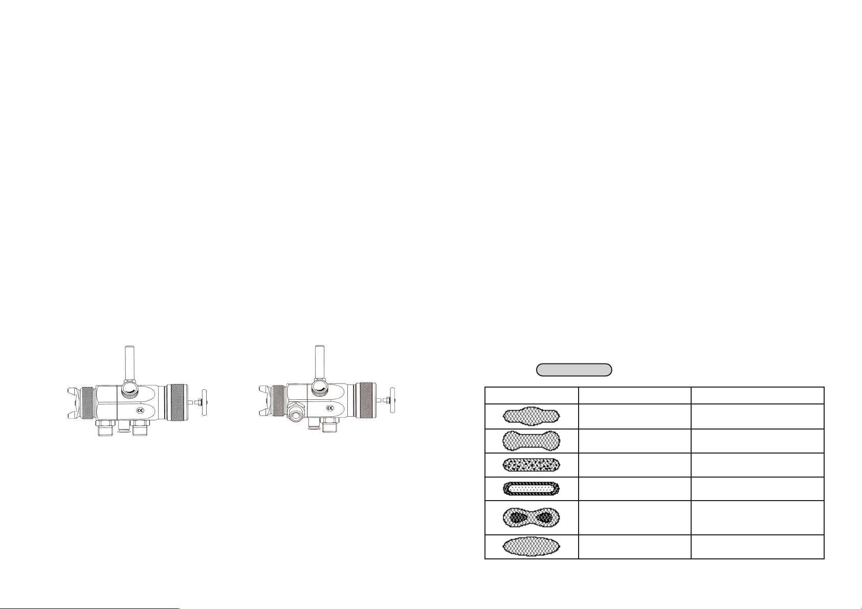
Fíje la pistola sobre un soporte estable y adecuado como en el ejemplo siguiente:
Para esto utilíce el bulón de fijación 1, diametro 8 mm.
A petición le suministramos otros dispositivos de fijación.
4.2 Empalmes de alimentación
Peligro
No confunda el empalme del aire de mando con el empalme del aire de pulverización
- riesgo de heridas.
M ST Z
ST Z
Empalme de
material
M = Empalme de material
ST = Empalme de aire de mando
Z = Empalme de aire de pulverización
Ya está la pistola completamente montada y lista para la puesta en servicio.
5 Manejo
5.1 Consignas de seguridad
Al utilizar la pistola respete en especial las siguientes consignas!
• Traiga una máscara protectora y ropa de trabajo reglamentaria. Las partículas
en suspensión son peligrosas para su salud.
• Traiga una protección contra ruidos en el area de trabajo. El nivel de ruido medi-
do a un metro de distancia es de unos 83 dB(A) y puede causar daños auditivos.
• No debe existir ninguna fuente de chispas en el area de trabajo. La pulverización
de materiales muy inflamables (lacas y adhesivos por ej.) aumenta los riesgos
de explosión e incendio.
5.2 Puesta en y fuera de servicio
Antes de poner la pistola en servicio asegúrese que:
• la presión del aire de mando esté presente a la pistola
• la presión de pulverización esté presente a la pistola
• la presión del material esté presente a la pistola.
Atención
La presión del material no debe exceder los
• 8 bar.
Sólo en este caso se podrán garantizar el buen funcionamiento y la seguridad de
la pistola.
Ajuste la presión del aire de mando al menos
• 4,5 bar,
para permitir la puesta en servicio.
La puesta y la parada de servicio se pueden activar mediante la válvula de mando
de 3/2 (ver instrucciones de servicio del fabricante).
Peligro
Cierre la presión de la pistola después de cada utilización - riesgo de explosión de
las mangueras con presión - riesgo de heridas.
5
4
1
WA 600
WA 610
l
l
l

Regulación de la presión del material
Este ajuste sólo se podra lograr a partir de la bomba o del calderín a presión.
Siga las instrucciones de servicio y las consignas de seguridad del fabricante.
Regulación de la presión del aire de pulverización
La presión del aire de pulverización se ajusta a partir de la válvula reductora de
presión del compresor. Siga las instrucciones de servicio y las consignas de
seguridad del fabricante.
Si desea modificar el chorro mas allá de las posibilidades de la pistola, se tendrá
que reconvertirla (véase 5.6 Modificación de la pistola).
WALTHER ofrece una amplia selección de conjuntos de cabezas neumáticas,
toberas y agujas.
5.5 Eliminar los defectos de la prueba de aplicación
El cuadro siguiente indica los ajustes que modifican la forma del chorro.
Resultado deseado
l
l
5.3 Pruebas de aplicación
Una prueba de aplicación es siempre necesaria cuando:
• se utiliza la pistola por primera vez
• se pulveriza un material después de otro
• se ha desmontado la pistola para mantenimiento o reparación
La prueba de aplicación puede realizarse sobre una pieza galvanizada, cartón o papel.
Peligro
Aleje la mano y otras partes del cuerpo de la tobera con presión de la pistola
- riesgo de heridas.
Peligro
Asegurese al pulverizar que ninguna persona se encuentre al alcance del chorro de
pulverización de la pistola - riesgo de heridas.
1. Ponga la pistola en servicio para realizar una prueba de aplicación (véase 5.2
Puesta eny fuera de servicio).
2. Controle la prueba y haga los ajustes necesarios directamente en la pistola
(véase 5.4 Regulación del chorro de pulverización).
5.4 Regulación del chorro de pulverización
Con las PILOT WA 600 / WA 610 la regulación del chorro se logra con los siguientes
ajustes.
Regulación del aire de pulverización
Por medio de las dos tuercas 1 y 2 se ajusta perfectamente el chorro de pulverización.
La tuerca B ajusta el chorro ancho o plano.
La tuerca R ajusta el chorro redondo.
Regulación del caudal de material
Gire la tuerca reguladora de alimentación de
material 1 (muesca en el casquillo elastico)
• hacia el interior, para reducir el caudal
• hacia el exterior, para incrementar el caudal.
Por medio de la barra de enganche 2, se
puede activar el paso del caudal de material
por la tobera sin abrir el aire de pulverización.
76
B
R
1
2
Prueba de
aplicación
Desviación Regulación necesaria
Chorro demasiado
grueso en el centro
• Incrementar lo ancho del chorro
Bordes demasiado
ancho
• Incrementar lo redondo del chorro
Chorro con salpicaduras
• Aumentar la presión del aire de
pulverización
Aplicación muy delgada en el centro
• Reducir la presión de pulverización
Chorro dividido en el
centro
• Aumentar le diámetro de la tobera
• Reducir la presión de pulverización
• Aumentar la presión del material
Aplicación ovalada
• Reducir la presión del material
• Aumentar la presión del aire de
pulverización

6.2 Limpieza completa
Para incrementar el tiempo de vida de la pistola y conservarla en buen estado de
funcionamiento es necesario limpiarla y lubricarla con regularidad.
Sólo utilice para la limpieza de la pistola agentes limpiadores recomendados por
el fabricante del material pulverizado y que no contengan los componentes
siguientes:
• hidrocarburos halogenisados
(como por ejemplo 1,1,1 triclorostano; cloruro de metileno etc.)
• ácidos o agentes limpiadores ácidos
• disolventes regenerados (agentes limpiadores diluidos)
• productos de decapado
Estos componentes generan reacciones químicas de oxidación al entrar en contacto con las piezas galvanizadas de la pistola.
WALTHER no asume ninguna responsabilidad en caso de daños causados por
una limpieza inadecuada.
Límpie la pistola
• antes de cada cambio de color o de material
• al menos una vez a la semana
• según el tipo de material o el nivel de ensuciamiento varias veces a la semana.
Atención
No deposite la pistola directamente en el disolvente o en cualquier otro agente
limpiador. Ya no se podría garantizar su buen funcionamiento.
Atención
No utilice superficies duras o objetos puntiagudos para limpiar su pistola. Las piezas de precisión podrían llegar a dañarse y perjudicar sus resultados de pulverización.
1. Desmonte la pistola, véase 5.5 Recambio de tobera y aguja.
2. Límpie la cabeza neumática y la tobera con un pincel y el agente lipiador.
3. Límpie el cuerpo de la pistola y las partes restantes con una gamuza empapa-
da con el agente limpiador.
4. Unte las piezas siguientes con una fina película de grasa:
• Manguito del pistón
• Anillo del pistón
• Aguja
• Resorte de la aguja
Para esto utilice un pincel y una grasa neutral exenta de ácidos o resinas.
Para volver a montar la pistola proceda en la orden inversa.
8
9
5.6 Modificación del chorro de pulverización
La cabeza neumática, la tobera y la aguja necesarias para la aplicación de un material particular forman un conjunto único, el sistema de tobera. Para garantizar la continuidad de su calidad de aplicación, cambie siempre el sistema en su conjunto.
Peligro
Antes de proceder a cualquier trabajo de reconversión, cierre la alimentación del
material y del aire a la pistola - riesgo de herida.
Recomendación
Antes de proceder a los pasos siguientes sirvase revisar el croquis de explosión
(hoja plegada) al principio de estas instrucciones de servicio.
Recambio de la cabeza neumática y de la tobera de material
1. Afloje la tuerca de la cabeza neumática pos 1.
2. Saque la cabeza neumática de la parte anterior pos. 3 de la pistola.
3. Afloje y saque la tobera pos. 2 de la parte anterior de la pistola (llave de 13).
Proceda en la orden inversa para el montaje.
Recambio de la aguja de material
1. Afloje y quite la barra de tracción pos. 22.
2. Destornille la tapa pos. 21 y saque el resorte de aguja pos. 20.
3. Afloje el casquillo roscado pos. 19, quite el resorte de pistón pos. 18 y saque la
aguja de material pos. 17.
Proceda en la orden inversa para el montaje.
6 Limpieza
6.1 Consignas de seguridad
• Antes de proceder a cualquier trabajo de mantinimiento, cierre la alimentación del
material y del aire a la pistola - riesgo de herida.
• No deberá existir ninguna fuente de chispa dentro del area de trabajo. La aplicaci-
ón de materiales muy inflamables (disolventes) aumenta los riesgos de explosión e
incendio.
• Siga las instrucciones de uso y las consignas de seguridad de los fabricantes de
materiales pulverizables y de solventes. Los materiales agresivos y causticos en
particular pueden perjudicar a su salud y ocasionar daños materiales.
l
l
l

7.1 Recambio de una empaquetadura de aguja defectosa
1. Cierre la presión de la pistola.
2. Quite la aguja de material pos. 17 como describe en el punto 5.6 Modificación..
3. Quite la parte anterior pos. 3 de la caja de pistón pos. 6 afloando los 3 tornillos
4. Saque la empaquetadura pos. 4 de aguja con una pequeña herramienta de
ancla.
5. Lubrique la empaquetadura nueva con una grasa neutral, sin ácidos ni resinas.
6. Coloque la empaquetadura nueva en el cuerpo de la pistola.
Para volver a montar las otras piezas proceda en la orden inversa.
Recomendación
La empaquetadura pos. 4 gastada no se deberá volver a utilizar. No se garantiza
que quede libre de fugas.
7.2 Recambio de tobera, aguja, resortes y juntas
Desmonte la pistola siguiendo las instrucciones del párrafo 5.6 Recambio de
tobera y aguja cuando las siguientes piezas se tengan que cambiar:
• tobera de material
• resorte de pistón
• aguja de material*
• resorte de la aguja*
• manguito*
Recomendación
Las piezas marcadas con una * deben untarse con una grasa neutral sin ácidos
ni resinas, antes de colocarse en el cuerpo de la pistola.
WALTHER le puede suministrar un kit de reparación para los modelos PILOT WA
600 y WA 610 con el conjunto de las piezas de desgaste rapido:
No. de articulo: V 16 600 02 . . 3 (WA 600 / WA 610)
Las piezas de desgaste aparecen con letras gruesas en la lista de las piezas de
recambio.
6.3 Limpieza de rutina
En caso de frequente cambio de color o (según el tipo del material) a la parada de
servicio, le podrá limpiar la pistola sin desmontarla.
Recomendación
Para preservar la seguridad del funcionamiento y la calidad de la pistola, úntela y
límpiela con regularidad (véase el párrafo 6.2 Limpieza completa).
Antes de proceder a la limpieza de rutina es preciso cumplir con la siguientes condiciones:
1. El calderín limpio se habra rellenado con el agente limpiador adecuado. La
presión del material estará presente a la pistola. El agente limpiador no se
deberá pulverizar.
2. Ponga la pistola en servicio, véase 5.2 Puesta en servicio.
3. No pare el servicio hasta que el agente limpiador salga completamente limpio.
Para evitar la puesta en servicio del sistema completo de pulverización, se puede
abrir manualmente la alimentación del material de los modelos PILOT WA 600 / WA
610.
El sistema de pulverización con presión cerrada puede ya quedar parado hasta su
próxima utilización.
1. Saque el disco de la pistola hacia atrás.
El canal de alimentación del material está abierto y se
pueden limpiar tubo y tobera.
2. Sólo suelte el disco cuando el agente limpiador salga
completamente claro.
7 Mantenimiento
Peligro
Antes de proceder a cualquier trabajo de mantenimiento cierre la alimentación de
material, de aire de pulverización y de aire de mando a la pistola - riesgo de heridas.
Recomendación
Antes de proceder a los pasos siguientes sirvase revisar el croquis de explosión al
principio de estas instrucciones de servicio.
10
11
l

8 Datos técnicos
Peso: 360 g
Anschluß:
para aire de pulverización: G 1/4
para aire de mando: CK 1/8 PK 4
para alimentación del material: G 3/8
Límetes de presión:
presión del aire de mando: min. 4,5 bar
presión del material: max. 8 bar
presión del aire de pulverización: max. 8 bar
Temperatura máxima
de servicio de la pistola 80 °C
Nivel de ruido
(medido a un metro
de distancia de la pistola) 83 dB (A)
Consumo de aire:
Presión de aire
de entrada: Chorro redondo Chorro ancho
1,0 bar 150 L/min. 180 L/min.
2,0 bar 210 L/min. 260 L/min.
3,0 bar 250 L/min. 310 L/min.
4,0 bar 280 L/min. 360 L/min.
5,0 bar 310 L/min. 400 L/min.
6,0 bar 340 L/min. 430 L/min.
Nos reservamos el derecho a modificaciones técnicas.
12
13
8 Identificación y eliminación de los fallos
Peligro
Antes de proceder a cualquier trabajo de limpieza o de mantenimiento cierre la alimentación de material, de aire de pulverización y de aire de mando - riesgo de heridas
.
9 Fluidos residuales
Los fluidos residuales resultando del mantenimiento y de la limpieza de la pistola se
deberán evacuar de acuerdo a las disposiciones y leyes relevantes.
Peligro
Siga las instrucciones de los fabricantes de materiales pulverizables y agentes limpiadores. Una evacuación precaria de los fluidos residuales es peligrosa para la salud
y el medio ambiente de los hombres y animales.
Defecto Causa Remedio
La pistola gotea
La tobera o la aguja están
ensuciadas
La tobera o la aguja están
dañadas
Desmonte y limpie la tobera o
la aguja, véase 5.6 Recambio
de tobera y de aguja
véase 5.6 Recambio de aguja o
tobera
La pistola no se
abre
La presión del aire de mando
está demasiado baja
Aumente la presión al menos
4,5 bar
El chorro sale con
irregularidad
Hace falta de material en el
depósito
Rellenar con material (véase
instrucciones de servicio del
fabricante)
La pistola sigue
soplando en condición de reposo
El manguito pos. 7 está dañado Cambiarlo
El material borbotea en el déposito
El aire de pulverización llega
por caudal de material en el
déposito - la tobera de material
o la cabeza neumática están
flojo
Limpiar, sujetar or cambiar las
piezas
Chorro de un lado Cuerno de la cabeza tapado Desmonte y limpie la cabeza
neumática
l
l
 Loading...