

Betriebsanleitung / Operating Instruction / Manuale d‘uso
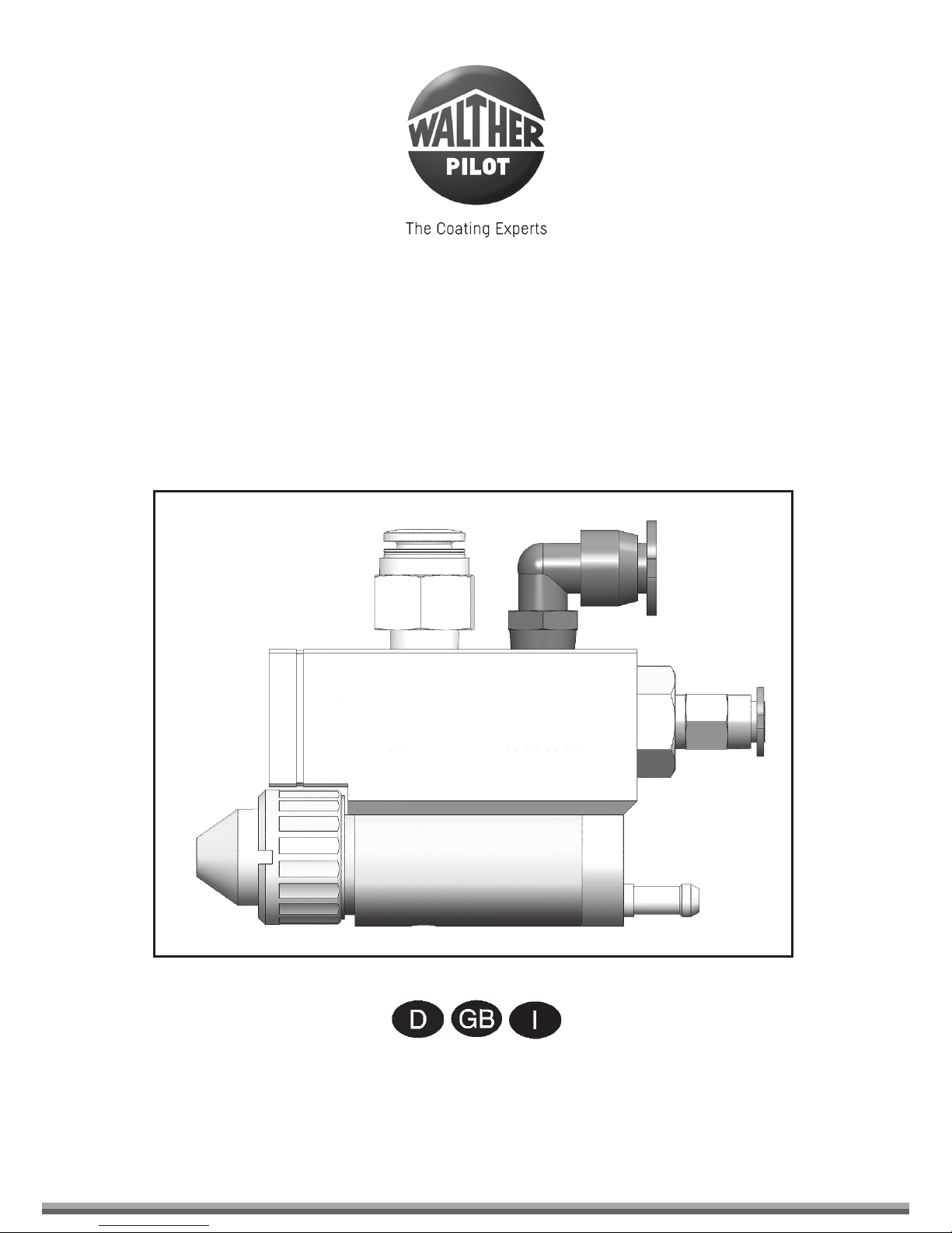
PILOT WA 55
Automatik-Spritzpistole / Automatic Spray Gun /
Pistola a spruzzo automatica
32
PILOT WA 55
7a
7b
Stand: Mai 2017
54
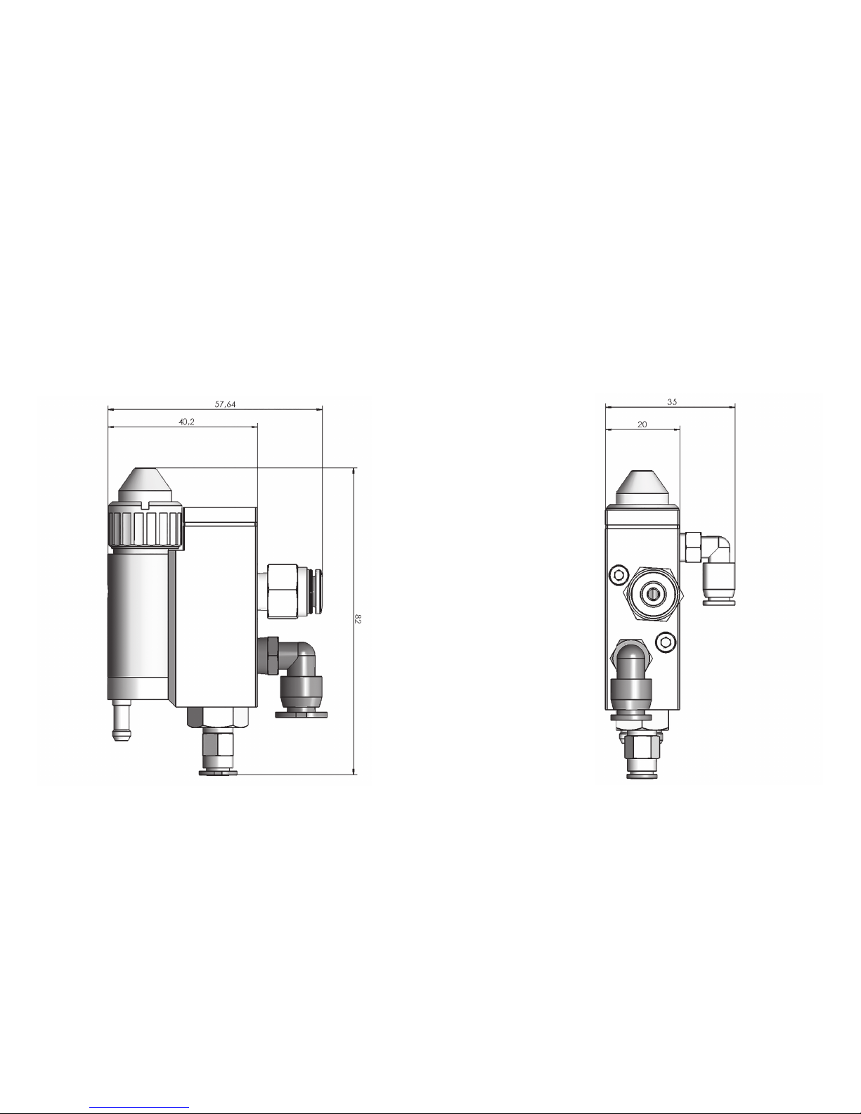
Maßblatt / Dimension Sheet / Disegno quotato

7
Seite 8 - 19
Page 20 - 31
Pagina 32 - 43
98
Inhaltsverzeichnis
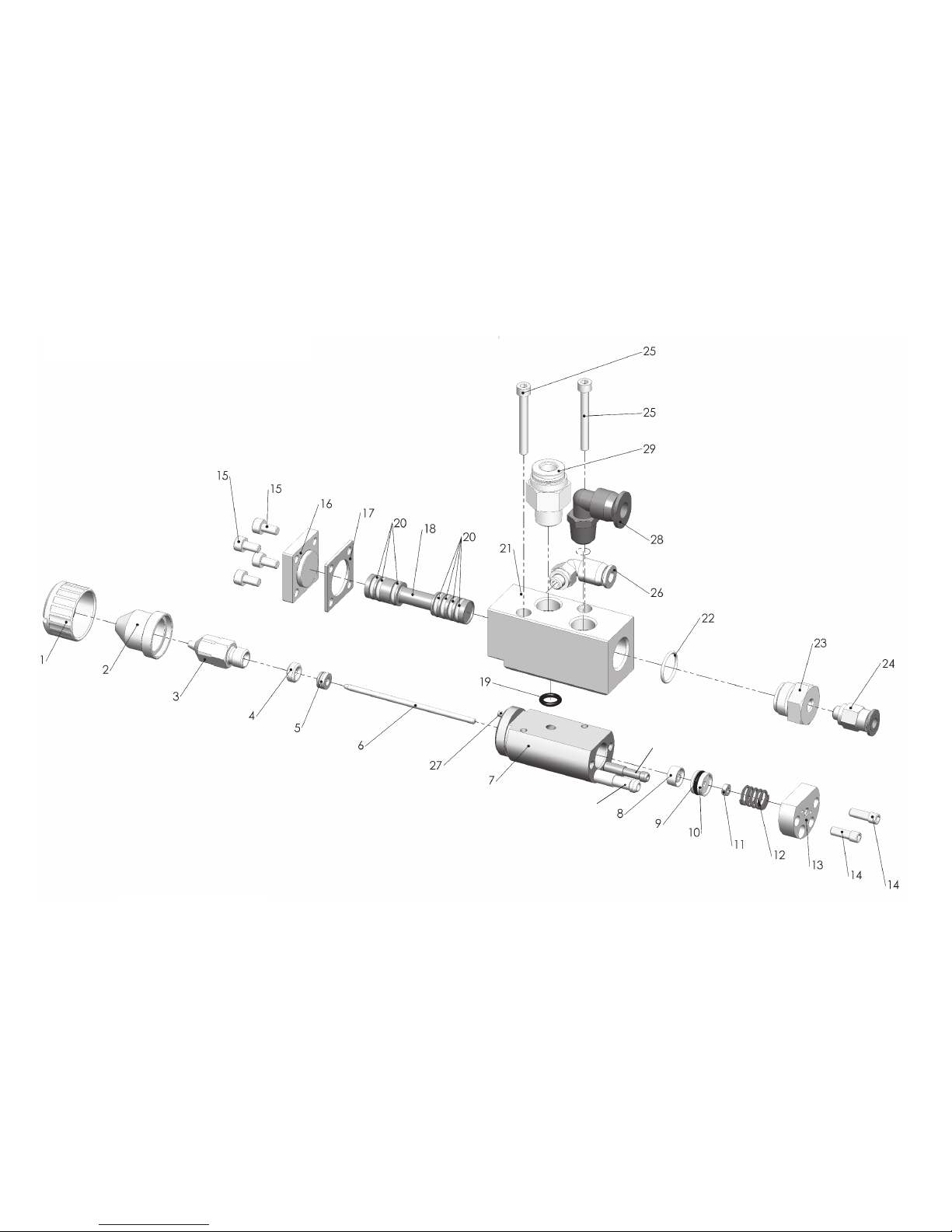
Explosionszeichnung 2
Maßblatt 4
Konformitätserklärung 9
Ersatzteilliste 10
1 Allgemeines 11
1.1 Kennzeichnung des Modells 11
1.2 Bestimmungsgemäße Verwendung 11
1.3 Sachwidrige Verwendung 11
2 Technische Beschreibung 12
3 Sicherheitshinweise 12
3.1 Kennzeichnung der Sicherheitshinweise 12
3.2 Allgemeine Sicherheitshinweise 13
4 Montage 13
4.1 Spritzpistole befestigen 13
4.2 Versorgungsleitungen anschließen 13
5 Bedienung 14
5.1 Sicherheitshinweise 14
5.2 Inbetrieb- und Außerbetriebsetzen 14
5.3 Spritzbild verändern 15
6 Reinigung und Wartung 15
6.1 Grundreinigung 15
6.2 Spülvorgang 16
7 Instandsetzung 17
7.1 Luftkopf und Materialdüse austauschen 17
7.2 Materialnadel austauschen 17
7.3 Nadeldichtung austauschen 17
7.4 O-Ringe des Nutkolbens austauschen 18
7.5 Federn und Dichtungen austauschen 18
8 Fehlersuche und -beseitigung 18
9 Entsorgung 19
10 Technische Daten 19
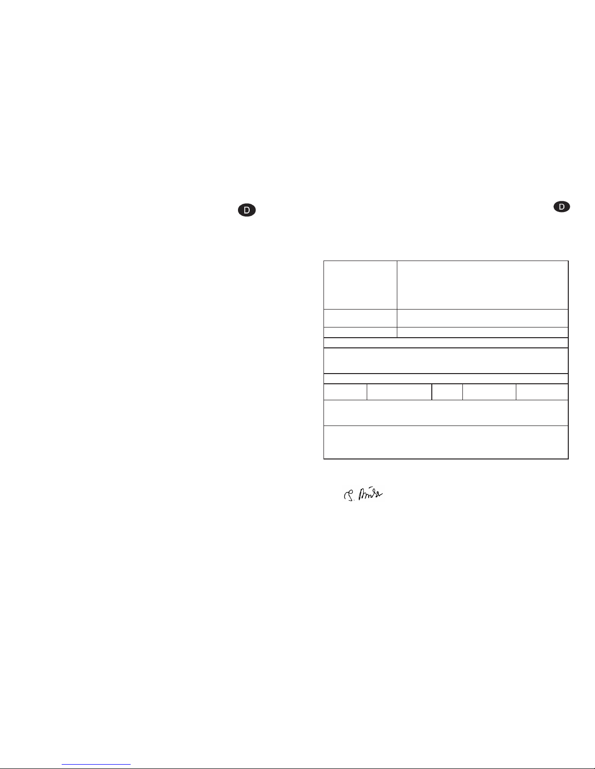
EG/EU-Konformitätserklärung
Wir, der Gerätehersteller, erklären in alleiniger Verantwortung, dass das Produkt in der
untenstehenden Beschreibung den einschlägigen grundlegenden Sicherheits- und
Gesundheitsanforderungen entspricht. Bei einer nicht mit uns abgestimmten Änderung
an dem Gerät oder bei einer unsachgemäßen Verwendung verliert diese Erklärung ihre
Gültigkeit.
Hersteller WALTHER Spritz- und Lackiersysteme GmbH
Kärntner Str. 18 - 30
D - 42327 Wuppertal
Tel.: +49(0)202 / 787 - 0
Fax: +49(0)202 / 787 - 2217
www.walther-pilot.de • e-mail: info@walther-pilot.de
Typenbezeichnung Automatische Spritzpistole
PILOT WA 55 V 20 301 51 XX3
Verwendungszweck Verarbeitung spritzbarer Materialien
Angewandte Normen und Richtlinien
EG-Maschinenrichtlinien 2006/42/EG
EN ISO 12100
DIN EN 1127-1
Spezifikation im Sinne der Richtlinie 2014/34/EU
Bevollmächtigt mit der Zusammenstellung der technischen Unterlagen:
Nico Kowalski, WALTHER Spritz- und Lackiersysteme GmbH, Kärntner Str. 18 - 30
D- 42327 Wuppertal
Besondere Hinweise :
Das Produkt ist zum Einbau in ein anderes Gerät bestimmt. Die Inbetriebnahme ist
so lange untersagt, bis die Konformität des Endproduktes mit der Richtlinie
2006/42/EG festgestellt ist.
Wuppertal, den 11. April 2017
Name: Torsten Bröker
Stellung im Betrieb: Leiter der Konstruktion und Entwicklung
Diese Erklärung ist keine Zusicherung von Eigenschaften im Sinne der Produkthaftung. Die Sicherheitshinweise
der Produktdokumentation sind zu beachten.
ppa.
1110
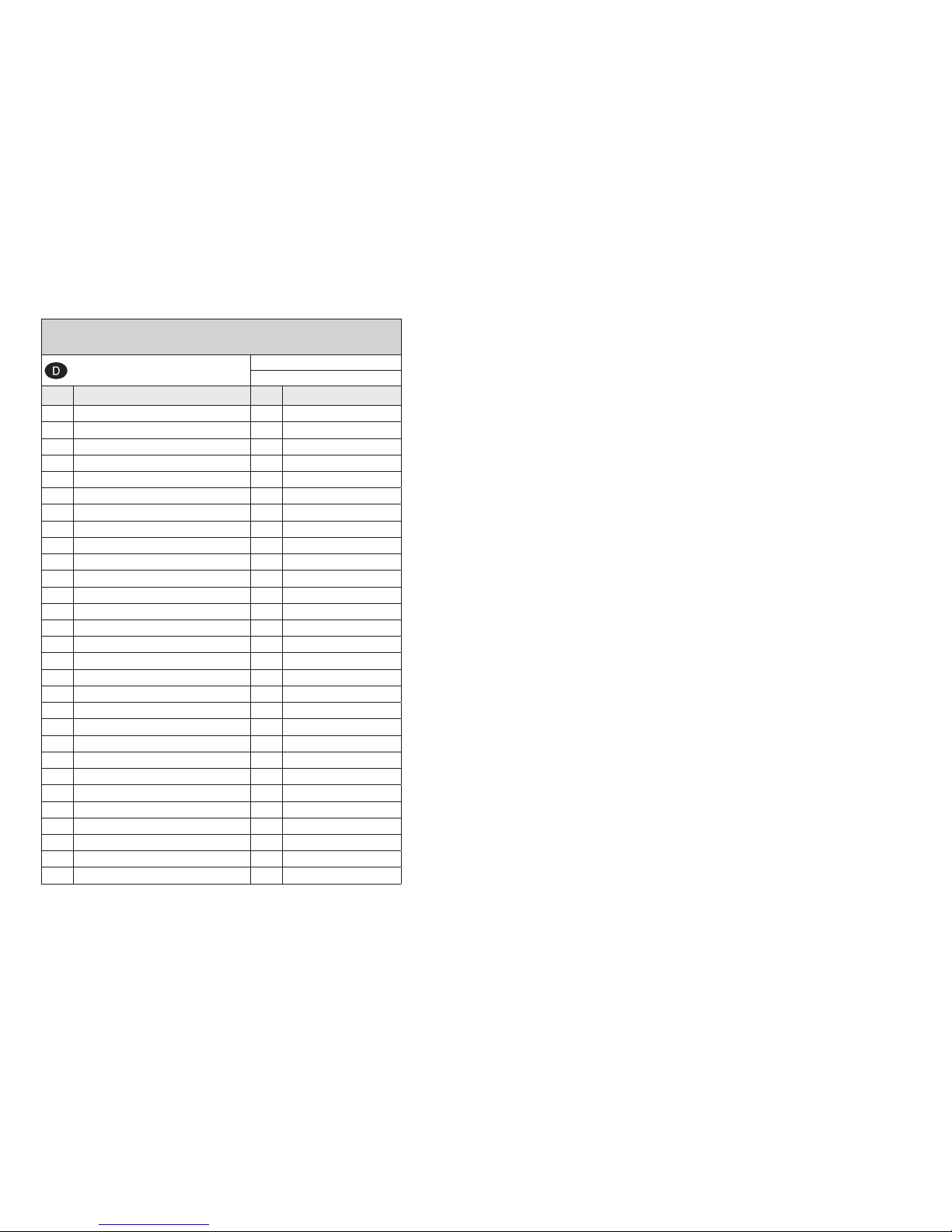
Ersatzteilliste PILOT WA 55
PILOT WA 55
V 20 301 51 XX3
Pos. Bezeichnung Stck Ersatzteilnummer
1 Überwurfmutter 1 V 21 300 03 000
2 Luftkopf 1,2 - 1,5 mm ø 1 V 20 336 34 125
3 Materialdüse 1,5 mm ø 1 V 20 336 23 153
4 Packungsschraube 1 V 20 305 04 003
5 Nadeldichtung kompl. 1 V 20 305 13 000
6 Materialnadel 1 V 20 300 30 XX3
7 Pistolenkörper kompl. incl.(7a + 7b) 1 V 20 300 01 003
8 Nutring 1 V 09 220 26 000
9 O-Ring 1 V 09 102 21 001
10 Kolben 1 V 20 305 03 004
11 Mutter 1 V 20 305 07 003
12 Kolbenfeder 1 V 20 305 12 005
13 Federbuchse 1 V 20 300 02 003
14 Kappenschraube 2 V 20 305 08 003
15 Zylinderschraube 4 V 20 307 08 003
16 Deckel 1 V 20 300 03 003
17 Dichtung 1 V 20 300 04 000
18 Nutkolben 1 V 20 300 05 003
19 O-Ring 1 V 09 102 38 001
20 O-Ring 7 V 20 300 06 000
21 Kolbenkörper 1 V 20 300 07 003
22 O-Ring 1 V 09 103 33 001
23 Federstopfbuchse 1 V 20 300 08 003
24 Steckverschraubung 1 V 66 001 53 304
25 Schraube 2 V 20 307 09 003
26 L-Steckverschraubung 1 V 66 101 53 333
27 Zylinderstift 1 V 20 300 09 003
28 L-Steckverschraubung 1 V 66 101 53 336
29 Steckverschraubung 1 V 66 001 33 043
Wir empfehlen, alle fettgedruckten Teile (Verschleißteile) auf Lager zu halten.
1 Allgemeines
1.1 Kennzeichnung des Modells
Modell: Automatische Spritzpistole PILOT WA 55
Typ: V 20 301 51 XX3
Hersteller: WALTHER Spritz- und Lackiersysteme GmbH
Kärntner Str. 18-30
D-42327 Wuppertal
Tel.: 0202 / 787-0
Fax: 0202 / 787-2217
www.walther-pilot.de • Email: info@walther-pilot.de
1.2 Bestimmungsgemäße Verwendung
Der automatische Spritzautomat PILOT WA 55 dient ausschließlich der Verarbeitung
wasserlöslicher Medien.
Sind Materialien, die Sie verspritzen wollen hier nicht aufgeführt, wenden Sie sich
bitte an WALTHER Spritz- und Lackiersysteme GmbH, Wuppertal. Sämtliche materialführenden Teile sind aus Edelstahl rostfrei gefertigt.
Die spritzbaren Materialien dürfen lediglich auf Werkstücke bzw. Gegenstände aufgetragen werden. .
Das Modell PILOT WA 55 ist kein handgeführter Spritzautomat und muss deshalb an
einer geeigneten Halterung befestigt werden.
Die bestimmungsgemäße Verwendung schließt auch ein, dass alle Hinweise und
Angaben der vorliegenden Betriebsanleitung gelesen, verstanden und beachtet
werden.
Beim Betreiben des Gerätes sind die Vorgaben dieser Betriebsanleitung unbedingt
einzuhalten. Die vorgeschriebenen Inspektions- und Wartungsintervalle sind einzuhalten.
Die Angaben auf den Geräteschildern bzw. die Angaben in dem Kapitel technische
Daten sind unbedingt einzuhalten und dürfen nicht überschritten werden. Eine
Überlastung des Gerätes muss ausgeschlossen sein.
Bei Anwendungen, bei denen der Ausfall des Gerätes zu einer Personengefährdung
führen könnten, sind betreiberseitig entsprechende Sicherheitsmaßnahmen vorzusehen.
Falls im Betrieb Auffälligkeiten erkannt werden, muss das Gerät sofort stillgesetzt
werden und es ist mit WALTHER Spritz- und Lackiersysteme GmbH Rücksprache zu
halten.
Erdung / Potentialausgleich
Es muss sichergestellt werden, dass die Spritzpistole separat oder in Verbindung mit
dem Gerät auf dem sie aufgebaut ist, ausreichend geerdet ist (max. Widerstand 106Ω).
1.3 Sachwidrige Verwendung
Die Spritzpistole darf nicht anders verwendet werden, als es im Abschnitt Bestimmungsgemäße Verwendung geschrieben steht. Jede andere Verwendung ist sach-
1312
widrig. Zur sachwidrigen Verwendung gehören z.B.:
• das Verspritzen von Materialien auf Personen und Tiere
• das Verspritzen von flüssigem Stickstoff.
• das Verspritzen von brennbaren Medien
2 Technische Beschreibung
Das Modell PILOT WA 55 arbeitet automatisch über eine Druckluftsteuerung und
wird über 3/2-Wege-Steuerventile angesteuert. Dazu können Hand-, Fuß- oder
Magnetventile eingesetzt werden.
Der Nutkolben (Pos. 18) befindet sich in der Ausgangsstellung und der Materialkanal
im Kolbenkörper ist offen. Zunächst wird die Zerstäuberluft (Pos. 7b) über ein
3/2-Wege-Steuerventil zugeschaltet. Danach wird über ein bauseitiges Steuerventil
die Steuerluft (Pos. 7a) geöffnet und die Materialzufuhr freigegeben. Die in den
Zylinderraum einströmende Druckluft betätigt den Steuerkolben (Pos. 10) und öffnet
die Materialzufuhr zur Materialdüse.
Das Schließen erfolgt in umgekehrter Reihenfolge.
Für den Spülvorgang wird das 3/2-Wege-Steuerventil für das Spülmittel (Pos. 28)
angesteuert. Danach wird die Steuerluft (Pos. 26) für den Kolbenkörper betätigt, die
den Nutkolben nach hinten schiebt, um den Spülkanal zu öffnen. Die in den
Zylinderraum einströmende Druckluft betätigt den Steuerkolben und öffnet die
Zufuhr zur Materialdüse.
Die Spritzpistole wird jetzt gespült. Der Spülvorgang dauert zwischen 5-10
Sekunden. Dann wird das Spülmittel abgeschaltet und die Zerstäuberluft kurz
betätigt, um die Materialdüse vom Spülmittel zu befreien.
Nach Betätigen der Steuerluft (Pos. 24), um den Nutkolben in die Ausgangsstellung
zu bewegen, wird die Spülmittelzufuhr unterbrochen und der Materialkanal wieder
geöffnet.
Danach wird die Steuerluft (Pos. 7a) für das Gehäuse durch das 3/2-Wege-Steuerventil unterbrochen und die im Zylinderraum befindliche Druckluft entweicht. Der
Federdruck der Kolbenfeder verschließt die Materialzufuhr zur Materialdüse.
Anschließend wird die Zerstäuberluft und die Spülmittelzufuhr über das 3/2-WegeSteuerventil abgeschaltet.
3 Sicherheitshinweise
3.1 Kennzeichnung der Sicherheitshinweise
Warnung
Das Piktogramm und die Dringlichkeitsstufe „Warnung“ kennzeichnen eine mögliche Gefahr für Personen. Mögliche Folgen: schwere oder leichte Verletzungen.
Achtung
Das Piktogramm und die Dringlichkeitsstufe „Achtung“ kennzeichnen eine mögliche Gefahr für Sachwerte. Mögliche Folgen: Beschädigung von Sachen.
Hinweis
Das Piktogramm und die Dringlichkeitsstufe „Hinweis“ kennzeichnen zusätzliche
Informationen für das sichere und effiziente Arbeiten mit der Spritzpistole.
3.2 Allgemeine Sicherheitshinweise
• Die einschlägigen Unfallverhütungsvorschriften sowie die sonstigen anerkannten
sicherheitstechnischen und arbeitsmedizinischen Regeln sind einzuhalten.
• Benutzen Sie die Spritzpistole nur in gut belüfteten Räumen. Im Arbeitsbereich ist
Feuer, offenes Licht und Rauchen verboten.
• Schalten Sie vor jeder Wartung und Instandsetzung die Luft- und Materialzufuhr
zur Spritzpistole drucklos - Verletzungsgefahr.
• Halten Sie beim Verspritzen von Materialien keine Hände oder andere Körperteile
vor die unter Druck stehende Düse der Spritzpistole - Verletzungsgefahr.
• Richten Sie die Spritzpistole nicht auf Personen und Tiere - Verletzungsgefahr.
• Beachten Sie die Verarbeitungs- und Sicherheitshinweise der Hersteller von
Spritz- material und Reinigungsmittel. Insbesondere aggressive und ätzende
Materialien können gesundheitliche Schäden verursachen.
• Die partikelführende Abluft ist vom Arbeitsbereich und Betriebspersonal fernzuhalten.
• Tragen Sie dennoch vorschriftsgemäßen Atemschutz und vorschriftsgemäße
Arbeitskleidung, wenn Sie mit der Spritzpistole Materialien verarbeiten.
• Umherschwebende Partikel gefährden Ihre Gesundheit.
• Tragen Sie im Arbeitsbereich der Spritzpistole einen Gehörschutz. Der erzeugte
Schallpegel der Spritzpistole beträgt ca. 83 dB (A).
• Achten Sie stets darauf, dass bei Inbetriebnahme, insbesondere nach Montageund Wartungsarbeiten alle Muttern und Schrauben fest angezogen sind.
• Verwenden Sie nur Original-Ersatzteile, da WALTHER nur für diese eine sichere
und einwandfreie Funktion garantieren kann.
•
Bei Nachfragen zur gefahrlosen Benutzung der Spritzpistole sowie der darin
verwendeten Materialien, wenden Sie sich bitte an WALTHER Spritz- und
Lackiersysteme GmbH, D-42327 Wuppertal.
4 Montage
Die Spritzpistole ist werkseitig komplett montiert. Bevor Sie die Spritzpistole in
Betrieb setzen können, sind die folgenden Tätigkeiten durchzuführen:
4.1 Spritzpistole befestigen
Befestigen Sie die Spritzpistole an einer geeigneten, standsicheren Halterung. Zum
Fixieren dient die Zentrierbohrung des Gehäuses.
4.2 Versorgungsleitungen anschließen
Warnung
Achten Sie darauf, dass die Anschlüsse nicht vertauscht werden - Verletzungsgefahr.

1514
Warnung
Material- und Luftschläuche, die mit einer Schlauchtülle befestigt werden, müssen
zusätzlich mit einer Schlauchschelle gesichert sein.
5 Bedienung
5.1 Sicherheitshinweise
Beachten Sie bei der Bedienung der Spritzpistole insbesondere die nachfolgenden
Sicherheitshinweise!
• Tragen Sie vorschriftsmäßigen Atemschutz und Arbeitskleidung, wenn Sie mit
der Spritzpistole Materialien verspritzen. Umherschwebende Partikel gefährden
Ihre Gesundheit.
• Tragen Sie im Arbeitsbereich der Spritzpistole einen Gehörschutz. Der erzeugte
Schallpegel der Spritzpistole von ca. 83 dB (A) kann einen Gehörschaden
verursachen.
• Im Arbeitsbereich ist Feuer, offenes Licht und Rauchen verboten. Beim
Verspritzen leicht entzündbarer Materialien (z. B. Lacke, Kleber) besteht
erhöhte Explosions- und Brandgefahr.
5.2 Inbetrieb- und Außerbetriebsetzen
Bevor Sie die Spritzpistole in Betrieb setzen können, müssen folgende Voraussetzungen erfüllt sein:
• Der Steuerluftdruck muss an der Spritzpistole anstehen.
• Der Zerstäuberluftdruck muss an der Spritzpistole anstehen.
• Der Materialdruck muss an der Spritzpistole anstehen.
• Der Spülmitteldruck muss an der Spritzpistole anstehen.
Achtung
Der Materialdruck darf nicht höher eingestellt sein als • 6 bar, da sonst kein funktionssicherer Betrieb der Spritzpistole gewährleistet ist. Stellen Sie den Steuerluftdruck
auf • mindestens 4,5 bar, damit die Spritzpistole in Betrieb gesetzt werden kann.
Sie können die Spritzpistole in und außer Betrieb setzen, indem Sie das 3/2-WegeSteuerventil betätigen (siehe Betriebsanleitung des Anlagenherstellers).
M
SP
ST 1
ST 2
Z
ST 3
Warnung
Die Spritzpistole muss nach Arbeitsende immer drucklos geschaltet werden. Die
unter Druck stehenden Leitungen können platzen und nahestehende Personen
durch das ausströmende Material verletzen.
5.3 Spritzbild verändern
Materialdurchflußmenge einstellen
Die Bestimmung der Materialdurchflußmenge ist anhand der Auswahl einer geeigneten Düsengröße vorzunehmen. Sie ist außerdem abhängig vom anstehenden
Materialdruck.
Materialdruck regulieren
Diese Einstellung nehmen Sie an der Pumpe oder am Druckbehälter vor. Beachten
Sie dabei die Anweisungen und Sicherheitshinweise des Herstellers.
Zerstäuberluftdruck regulieren
Der Zerstäuberluftdruck wird stufenlos über ein in der Anlage angeordnetes Druckluft-Reduzierventile eingestellt. Beachten Sie die Anweisungen und Sicherheitshinweise des Herstellers.
Steuerluftdruck regulieren
Der Steuerluftdruck wird am Druckluft-Reduzierventil der Kompressoranlage eingestellt. Beachten Sie die Anweisungen und Sicherheitshinweise des Herstellers.
6 Reinigung und Wartung
• Schalten Sie vor jeder Wartung die Steuer- und Zerstäuberluft sowie die
Materialzufuhr zur Spritzpistole drucklos - Verletzungsgefahr.
• Im Arbeitsbereich ist Feuer, offenes Licht und Rauchen verboten. Beim Verspritzen leichtentzündlicher Materialien (z.B. Reinigungsmittel) besteht erhöhte
Explosions- und Brandgefahr.
• Beachten Sie die Sicherheitshinweise des Reinigungsmittel Herstellers.
Insbesondere aggressive und ätzende Reinigungsmittel können gesundheitliche
Schäden verursachen.
6.1 Grundreinigung
Damit die Lebensdauer und die Funktion der Spritzpistole lange erhalten bleibt,
muss die Spritzpistole regelmäßig gereinigt und geschmiert werden.
Verwenden Sie zur Reinigung der Spritzpistole nur Reinigungsmittel, die vom
Hersteller des Spritzmaterials angegeben werden und die folgenden Bestandteile
nicht enthalten:
• halogenierte Kohlenwasserstoffe (z. B. 1,1,1, Trichlorethan, Methylen-Chlorid
usw.)
• Säuren und säurehaltige Reinigungsmittel
• regenerierte Lösemittel (sog. Reinigungsverdünnungen)
M = Materialanschluss (QSM-1/8-6)
SP = Spülmittelanschluss (QSML-1/8-4)
ST 1 = Steuerluftanschluss (QSM-M5-4):
Material offen bzw. Spülmittel zu
ST 2 = Steuerluftanschluss (QSML-M5-4):
Material zu bzw. Spülmittel offen
Z = Zerstäuberluftanschluss
(M 3-4 mm ø)
ST 3 = Steuerluftanschluss (M 3-2 mm ø):
Materialnadel auf
Die Spritzpistole ist nun vollständig montiert
und kann in Betrieb gesetzt werden.

1716
• Entlackungsmittel.
Die o.g. Bestandteile verursachen an galvanisierten Bauteilen chemische Reaktionen
und führen zu Korrosionsschäden.
Für Schäden, die aus einer derartigen Behandlung herrühren, übernimmt WALTHER
Spritz- und Lackiersysteme keine Gewährleistung.
Reinigen Sie die Spritzpistole
• vor jedem Farb- bzw. Materialwechsel.
• mindestens einmal wöchentlich.
• materialabhängig und je nach Verschmutzungsgrad mehrfach wöchentlich.
Achtung
Legen Sie die Spritzpistole nie in Lösemittel oder ein anderes Reinigungsmittel. Die
einwandfreie Funktion der Spritzpistole kann sonst nicht garantiert werden.
Achtung
Verwenden Sie zur Reinigung keine harten oder spitzen Gegenstände. Präzisionsteile der Spritzpistole könnten sonst beschädigt werden und das Spritzergebnis
verschlechtern.
1. Zerlegen Sie die Pistole gemäß 7 Instandsetzung.
2. Reinigen Sie den Luftkopf und die Materialdüse mit einem Pinsel und dem
Reinigungsmittel.
3. Reinigen Sie alle übrigen Bauteile und den Pistolenkörper mit einem Tuch und
dem Reinigungsmittel.
4. Bestreichen Sie folgende Teile mit einem dünnen Fettfilm:
• Feder des Nutkolbens
• O-Ring des Kolbens
• Nutkolben
• Materialnadel
• Kolbenfeder
• Kolben
Verwenden Sie dazu ein säurefreies, nicht harzendes Fett und einen Pinsel.
Anschließend wird die Spritzpistole in umgekehrter Reihenfolge zusammengesetzt.
6.2 Spülvorgang
In Betrieb wird das Model PILOT WA 55 nach jedem Spritzvorgang automatisch
gereinigt. Es ist dennoch zu beachten:
1. Der letzte Arbeitsgang vor dem Ausserbetriebsetzen sollte immer das Spülen
sein.
2. Setzen Sie die Spritzpistole erst außer Betrieb, wenn diese nur noch klares
Reinigungsmittel verspritzt.
Die gesamte Spritzanlage sollte nun bis zum nächsten Einsatz drucklos geschaltet
werden.
Hinweis
Reinigen und schmieren Sie die Spritzpistole dennoch regelmäßig gemäß Abschnitt
6.1 Grundreinigung. Sie erhalten so die sichere Funktion der Spritzpistole.
7 Instandsetzung
Warnung
Schalten Sie vor jeder Instandsetzung die Steuer- und Zerstäuberluft sowie die
Materialzufuhr zur Spritzpistole drucklos - Verletzungsgefahr.
Hinweis
Zur Durchführung der im Folgenden aufgeführten Arbeitsschritte benutzen Sie bitte
die Zeichnung am Anfang dieser Betriebsanleitung.
7.1 Luftkopf und Materialdüse austauschen
1. Schrauben Sie die Überwurfmutter (Pos. 1) ab und entfernen den Luftkopf
(Pos. 2).
2. Schrauben Sie die Materialdüse (Pos. 3) aus dem Gehäuse (Pos. 7).
Der Einbau geschieht in umgekehrter Reihenfolge.
7.2 Materialnadel austauschen
1. Entfernen Sie alle Schläuche von den Anschlüssen des Gehäuse (Pos. 7).
2. Schrauben Sie die beiden Kappenschrauben (Pos. 14) aus dem Gehäuse und
ziehen Sie Federbuchse (Pos. 13) nach hinten heraus .
3. Entfernen Sie die Kolbenfeder (Pos. 12) und ziehen den Kolben (Pos. 10) mit
der Materialnadel (Pos. 6) heraus.
4. Lösen Sie die Mutter (Pos. 11) und schrauben Sie die Materialnadel aus dem
Kolben.
5. Bestreichen Sie das Gewinde der neuen Materialnadel mit einem Kleber (zum
Abdichten) und schrauben Sie die Nadel in den Kolben.
6. Schrauben Sie die Mutter zum Kontern auf die Materialnadel. Das Einstellmaß
der Materialnadel von Nadelspitze bis Kolben beträgt 46,8 mm.
Der Einbau geschieht in umgekehrter Reihenfolge.
7.3 Nadeldichtung austauschen
1. Bauen Sie den Luftkopf, Materialdüse und Materialnadel, wie unter 7.1 und 7.2
beschrieben, aus.
2. Schrauben Sie die Packungsschraube (Pos. 4) aus dem Gehäuse.
3. Ziehen Sie die Nadeldichtung (Pos. 5) mit einem Hilfswerkzeug aus ihrem Sitz.
Verwenden Sie hierzu einen festen Draht, dessen Ende zu einem kleinen Haken
umgebogen ist.
Der Einbau geschieht in umgekehrte Reihenfolge.
Hinweis
Die aus dem Pistolenvorsatz entnommene Nadeldichtung (Pos. 5) darf nicht wiederverwendet werden, da sonst eine funktionssichere Dichtwirkung nicht gewährleistet
ist.

1918
7.4 O-Ringe des Nutkolbens austauschen
1. Schrauben Sie die Federstopfbuchse (Pos. 23) aus den Kolbenkörper (Pos. 21).
2. Ziehen Sie den Nutkolben (Pos. 18) aus den Kolbenkörper nach hinten heraus.
3. Tauschen Sie die sechs O-Ringe (Pos. 20) vom Nutkolben aus.
Der Einbau erfolgt in umgekehrter Reihenfolge.
Hinweis
Die aus dem Nutkolben entnommene O-Ringe (Pos. 20) dürfen nicht wiederverwendet werden, da sonst eine funktionssichere Dichtwirkung nicht gewährleistet ist.
7.5 Federn und Dichtungen austauschen
Zerlegen Sie die Spritzpistole gemäß Abschnitt 7.1 und 7.2, wenn die folgenden
Bauteile ausgetauscht werden müssen:
• Materialdüse
• Materialnadel*
• Kolbenfeder*
• O-Ring des Kolbens*
• O-Ringe des Nutkolbens*
• Nutring*
Hinweis
Die mit * gekennzeichneten Bauteile müssen vor dem Einbau in das Pistolengehäuse mit einem säurefreien, nicht harzenden Fett eingefettet werden.
8 Fehlersuche und -beseitigung
Warnung
Schalten Sie vor jeder Wartung und Instandsetzung die Steuer- und Zerstäuberluft
sowie Materialzufuhr zur Spritzpistole drucklos - Verletzungsgefahr.
Fehler Ursache Abhilfe
Pistole tropft
Materialnadel oder -düse verschmutzt oder beschädigt
Materialnadel oder -düse ausbauen
und reinigen oder austauschen,
siehe 7 Instandsetzung
Pistole öffnet nicht Steuerluft zu niedrig
Steuerluftdruck erhöhen auf min.
4,5 bar
Material sprudelt
im Materialbehälter
Zerstäuberluft gelangt über
Materialkanal in den Materialbehälter. Materialdüse oder
Luftkopf nicht richtig angezogen.
Teile reinigen, anziehen oder ersetzen
Stoßweiser oder
flatternder
Spritzstrahl
zu wenig Material im
Materialbehälter
Material auffüllen (siehe Betriebsanleitung des Anlagenherstellers)
9 Entsorgung
Die bei der Reinigung und Wartung anfallenden Materialien sind den Gesetzen und
Vorschriften entsprechend sach- und fachgerecht zu entsorgen.
Warnung
Beachten Sie insbesondere die Hinweise des Herstellers der Spritz- und Reinigungsmittel. Unachtsam entsorgtes Material gefährdet die Gesundheit von Mensch und
Tier.
10 Technische Daten
Gewicht: 232 g
Anschluss:
Zerstäuberluft M 3-4 mm ø
Steuerluft (Kolbenkörper) QSML-M5-4
Steuerluft (Gehäuse) M 3-2 mm ø
Materialzufuhr QSM-1/8-6
Spülmittel QSML-1/8-4
Druckbereiche:
Steuerluft mind. 4,5 bar
Materialdruck max. 6 bar
Zerstäuberluft max. 6 bar
Spülmittel max. 6 bar
max. Betriebstemperatur
der Spritzpistole 80 °C
Schallpegel
(gemessen in ca. 1 m
Abstand zur Spritzpistole) 83 dB (A)
Luftverbrauch
Zerstäuberluftdruck Luftverbrauch
1,0 bar 50 l/min
2,0 bar 60 l/min
3,0 bar 70 l/min
4,0 bar 85 l/min
5,0 bar 90 l/min
6,0 bar 100 l/min
Technische Änderungen vorbehalten.

2120
Contents
Exploded Drawing 2
Dimension Sheet 4
Declaration of CE-Conformity 21
Replacement parts 22
1 General 23
1.1 Identification of Model Version 23
1.2 Normal Use 23
1.3 Improper Use 23
2 Technical Description 24
3 Safety Instructions 24
3.1 Identification of safety instructions 24
3.2 General Safety Instructions 25
4 Assembly 25
4.1 Mounting of the Spray Gun 25
4.2 Connection of Input Lines 25
5 Operational Handling 26
5.1 Safety Warnings 26
5.2 Starting/Stopping Requirements 26
5.3 Spray Pattern Adjustments 27
6 Cleaning and Maintenance 27
6.1 Cleaning - Complete 27
6.2 Cleaning Process 28
7 Repairs 29
7.1 Replacement of Air Cap and Material Nozzle 29
7.2 Replacement of Material Needle 29
7.3 Replacement of Needle Seal 29
7.4 Replacement of O-rings of the Flute-Piston 30
7.5 Replacement of Springs and Seals 30
8 Troubleshooting and Corrective Action 30
9 Disposal of Cleaning and Servicing Substances 31
10 Technical Data 31
Declaration of EC/EU-Conformity
We, the manufacturers of the equipment, hereby declare under our sole responsibility
that the product(s) described below conform to the essential safety requirements. This
declaration will be rendered invalid if any changes are made to the equipment without
prior consultation with us.
Manufacturer WALTHER Spritz- und Lackiersysteme GmbH
Kärntner Str. 18 - 30
D - 42327 Wuppertal
Tel.: +49(0)202 / 787 - 0
Fax: +49(0)202 / 787 - 2217
www.walther-pilot.de • e-mail: info@walther-pilot.de
Type Designation Automatic Spray Gun
PILOT WA 55 V 20 301 51 XX3
Intended purpose Processing of sprayable media
Applied Standards and Directives
EU-Mechanical Engineering Directives 2006/42/EC
EN ISO 12100
DIN EN 1127-1
Specification according 2014/34/EU
Authorized with the compilation of the technical file:
Nico Kowalski, WALTHER Spritz- und Lackiersysteme GmbH, Kärntner Str. 18 - 30
D- 42327 Wuppertal
Special remarks :
The named product is intended for installation in other equipment. Commissioning is
prohibited until such time as the end product has been proved to conform to the
provision of the Directives 2006/42/EC.
Wuppertal, the 11th of April 2017
Name: Torsten Bröker
Position: Manager, Design and Development
This Declaration does not give assurance of properties in the sense of product liability. The safety instructions
provided in the product documentation must be observed at all times.
p.p.

2322
1 General
1.1 Identification of Model Version
Model: Automatic Spray Gun PILOT WA 55
Type: V 20 301 51 XX3
Manufacturer: WALTHER Spritz- und Lackiersysteme GmbH
Kärntner Str. 18-30
D-42327 Wuppertal
Tel.: 00 49 202 / 787-0
Fax: 00 49 202 / 787-2217
www.walther-pilot.de • Email: info@walther-pilot.de
1.2 Normal Use
The automatic spray gun PILOT WA 55 must be used only for processing watersoluble media.
If you intend to spray materials that are not listed here, please contact WALTHER
Spritz- und Lackiersysteme GmbH, Wuppertal. All parts which are in contact with the
material are made of stainless steel.
The sprayable materials must be sprayed only on workpieces or objects. The model
PILOT WA 55 is not a manual spray gun and must therefore be mounted in a suitable bracket.
The term normal use also implies that any and all safety warnings, operational handling details, etc., as stated in these operating instructions, must be carefully read,
understood and duly complied with.
The technical data indicated on the equipment rating plates and the specifications in
the chapter „Technical Data“ must be complied with at all times and must not be
exceeded. An overloading of the equipment must be ruled out.
The equipment may be used in potentially explosive atmospheres only with the
authorisation of the relevant supervisory authority.
The operator must provide corresponding safety measures for all applications in
which the breakdown of the equipment might lead to danger to persons.
If any irregularities are observed while the equipment is in operation, the equipment
must be put out of operation immediately and WALTHER Spritz- und Lackiersysteme
must be consulted.
Grounding / Equipotential Bonding
You must ensure that the spray gun is properly earthed (grounded) either separately
or in connection with the equipment with which it is being used (max. resistance 106
Ω).
1.3 Improper Use
This spray gun shall not be used for purposes other than set forth in the above
Chapter Normal Use. Any other form of use and/or application is prohibited.
Replacement parts PILOT WA 55
PILOT WA 55
V 20 301 51 XX3
Item Description Qty. Art.-No.
1 Sleeve nut 1 V 21 300 03 000
2 Round jet air cap 1,2 - 1,5 mm ø 1 V 20 336 34 125
3 Material nozzle 1,5 mm ø 1 V 20 336 23 153
4 Packing screw 1 V 20 305 04 003
5 Needle seal compl. 1 V 20 305 13 000
6 Material needle 1 V 20 300 30 XX3
7 Housing compl. (7a + 7b) 1 V 20 300 01 003
8 Lip seal 1 V 09 220 26 000
9 O-ring 1 V 09 102 21 001
10 Piston 1 V 20 305 03 004
11 Nut 1 V 20 305 07 003
12 Piston spring 1 V 20 305 12 005
13 Spring bushing 1 V 20 300 02 003
14 Cap screw 2 V 20 305 08 003
15 Cylinder head screw 4 V 20 307 08 003
16 Closure head 1 V 20 300 03 003
17 Seal 1 V 20 300 04 000
18 Flute-piston 1 V 20 300 05 003
19 O-ring 1 V 09 102 38 001
20 O-Ring 7 V 20 300 06 000
21 Piston body 1 V 20 300 07 003
22 O-Ring 1 V 09 103 33 001
23 Spring gland 1 V 20 300 08 003
24 Push-in fitting 1 V 66 001 53 304
25 Screw 2 V 20 307 09 003
26 Push-in threated/L-fitting 1 V 66 101 53 333
27 Cylindrical pin 1 V 20 300 09 003
28 Push-in threated/L-fitting 1 V 66 101 53 336
29 Push-in fitting 1 V 66 001 33 043
We recommend all bold-faced replacement parts (wearing parts) are held on stock.

2524
Improper use is for example:
• spraying of material onto persons and animals
• spraying of liquid nitrogen, etc.
• spraying of flammable media
2 Technical Description
The model PILOT WA 55 is operated automatically by compressed air and is controlled via 3/2-way control valves. Hand-operated, foot-operated or solenoid-valveoperated valves can be used for this purpose.
The flute-piston is in the starting position and the material duct in the piston body is
open. At frirst the atomising air (item 7b) is switched on by the 3/2-way-control valve.
Afterwards the control air (item 7a) is opened by a control valve (provided by customer) and the material supply is disconnected. The compressed air flowing into the
cylinder chamber moves the control piston and opens the material supply to the
material nozzle.
The closing takes place in reverse order.
For the cleaning process the 3/2-way control valve for the scavenger (item 28) is
activated. Afterwards the control air (item 26) for the piston body is actuated to push
backward the flute-piston to open the duct for the scavenger. The compressed air
flowing into the cylinder chamber moves the control piston and opens the supply to
the material nozzle.
Now the spray gun is fushed. The cleaning process takes 5 - 10 seconds.
The closing takes place in reverse order. Then the scavenger is switched off and the
atomizing air is activated short to clean the material nozzle from the scavenger.
By activating the control air (item 24) to push the flute-piston in the starting position
the scavenger supply is closed and the material supply is already opened.
After the control air (item 7a) for the housing is interrupted by the 3/2-way valve, the
compressed air in the cylinder chamber is allowed to escape. The spring pressure of
the piston spring shuts off the material supply to the material nozzle.
After this, the atomising air and the scavenger are switched off by the 3/2-way valve.
3 Safety instructions
3.1 Identification of safety instructions
Warning
The pictogram and the urgency level “Warning“ identify a possible danger to persons.
Possible consequences: Slight to severe injuries.
Caution
The pictogram and the urgency level “Caution“ identify a possible danger to material assets.
Possible consequences: Damage to material assets.
Note
The pictogram and the urgency level “Note“ identify additional information for the
safe and efficient operation of the spray gun.
3.2 General Safety Instructions
• All applicable accident prevention rules and regulations as well as other recognis-
ed industrial safety and health rules and regulations must be observed at all times.
• Use the spray gun only in well-ventilated rooms. Fire, naked flames and smoking
are strictly prohibited within the working area.
• Before carrying out maintenance or servicing work, always ensure that the air and
material feed to the spray gun have been depressurised. Risk of injury!
• When spraying materials, do not place your hands or other parts of the body in
front of the pressurised nozzle or the spray gun. Risk of injury!
• Never point the spray gun at persons or animals. Risk of injury!
• Always observe the spraying and safety instructions given by the manufacturers of
the spraying material and the cleaning agent. Aggressive and corrosive materials
in particular can be harmful to health.
• Exhaust air containing particles (overspray) must be kept away from the working
area and personnel. In spite of these measures, always wear the regulation breathing masks and protective overalls when using the gun. Airborne particles represent a serious health hazard!
• Always wear hearing protection when using the gun or when in the vicinity of a gun
that is in use. The noise level generated by the spray gun is approx. 83 dB (A).
• After carrying out assembly or maintenance work, always ensure that all nuts, bolts
and screw connections have been fully tightened before the gun is used.
• Use only original replacement parts, since WALTHER can only guarantee safe and
fault-free operation for original parts.
• For further information on the safe use of the spray gun and the spraying materials,
please contact WALTHER Spritz- und Lackiersysteme GmbH, D-42327 Wuppertal,
Germany.
4 Assembly
The spray gun is delivered fully assembled. Before using it, the following steps
should be carried out:
4.1 Mounting of Spray Gun
Install the gun in a suitable and stable mounting device. Use the centre hole of the
housing for locate the gun.
4.2 Connection of Input Lines
Warning
Make sure not to confuse the control and atomizing air connections -risk of injury.

2726
Warning
Material and air hoses which are installed with a hose grommet must be additionally
secured with a hose clamp.
5 Operational Handling
5.1 Safty Warnings
Please pay special attention to the following safety warnings prior to taking this
spray gun into operation!
• Wear proper respiratory protection masks and protective overalls, whenever you
are operating this spray gun. Air-borne particles represent a health hazard.
• Make sure to wear suitable haering protectors. The gun produces sound levels
of up to 83 dB (A) which may cause hearing defects.
• Open fires, naked lights and smoking prohibited in the working area. Spraying
of readily flammable media such as paints and adhesive compounds is always
accompanied by the risk of fire and explosion.
5.2 Starting/Stopping Requirements
The following requirements must be met before the spray gun is operated:
• The control air pressure must be available at the gun.
• The atomizing air pressure must be available at the gun.
• The material pressure must be available at the gun.
• The scavenger pressure must be avaiable at the gun.
Caution
The material pressure should not exceed • 6 bar, since otherwise the operational
reliability of the spray gun will be impaired. The control air pressure should be set at
• minimum of 4,5 bar, in order to operate the gun.
The operation of the spray gun can be started/stopped by way of the 3/2-way control
valve (see the operating instructions of the plant systems manufacturer).
Warning
It is important to remember to relieve the spray gun of all pressures when work is
terminated. Lines left under pressure may burst and the released material may injure any persons in the vicinity.
5.3 Spray Pattern Adjustment
Material flow rate
In order to establish the material flow rate choose a suitable nozzle size. Furthermore
it is dependent on the upcoming material pressure.
Regulate the material pressure
Adjust the material pressure at the pump or the material pressure tank - make sure
to follow relevant instructions and safety warnings of the manufacturer!
Regulate the atomizing air pressure
The atomizing air pressure is continuously variable adjusted at the arranged air
pressure-reducer in the plant system. Please comply with the operating instructions
and safety warnings issued by the manufacturer.
Regulate the control air pressure
The control air pressure is to be adjusted at the air pressure reducing valve of the
compressor system. Please comply with the operating instructions and safety warnings issued by the manufacturer.
6 Cleaning and Maintenance
• Make sure that the spray gun is in unpressurised condition, i.e. all air and material inputs must be shut off - if not, imminent Risk of Injury.
• Open fires, naked lights and smoking is prohibited in the working area. There is
an increasing risk of fire and explosion, when spraying readily flammable media
(such as cleaning solutions).
• Observe all processing specifactions and safety warnings issued by the manufacturer of cleaning media. Especially aggressive and corrosive media represents risks and hazard to personal health.
6.1 Cleaning - Complete
Regular cleaning and lubrication of the spray gun has to be performed, in order to
increase the service life and the function of the spray gun.
Clean the gun only with cleaning solutions recommended by the manufacturer of the
spraying material, which do not contain any of the following constituents:
• halogenated hydrocarbons (e.g. 1,1,1, trichloroethane; methylene chloride, etc.)
• acids and acidiferous cleaning solutions
• regenerated solvents (so-called cleaning dilutions)
• paint removers
M = Material connection (QSM-1/8-6)
SP = Scavenger connection (QSML-1/8-4)
ST 1 = Control air connetion (QSM-M5-4):
Material open and scavenger close
ST 2 = Control air connection (QSML-M5-4)
Material close and scavenger open
Z = Atomising air connection
(M 3-4 mm ø)
ST 3 = Control air connection
(M 3-2 mm ø): Material needle open
The spray gun is now properly installed and
ready for operation.
M
SP
ST 1
ST 2
Z
ST 3

2928
The above constituents cause chemical reactions with electroplated components
resulting in corrosion damage. WALTHER Spritz- und Lackiersysteme is not responsible for damages resulting from this kind of treatment.
Clean the spray gun
• prior to each change of the spraying medium
• at least once a week
• as often as may be required by the spraying medium handled and the resulted
degree of fouling.
Caution
Never immerse the spray gun in solvent or any other cleaning solution as such
measure is very likely to affect the functional reliability and efficiency of the gun.
Caution
Do not use any hard, pointed or sharp-edged objects when cleaning the spray gun,
as the precision-made parts can be easily damaged and are likely to affect your
spraying results.
1. Dismantle the gun as described in section 7 Repairs.
2. Clean the air cap and the material nozzle with a soft brush and cleaning fluid.
3. Clean all other components and the gun body with a soft cloth and cleaning fluid.
4. Coat the following parts with a thin layer of grease:
• Spring of the flute-piston
• O-ring of the piston
• Flute-piston
• Material needle
• Piston spring
• Piston
Use non-acidic, non-resinogenic grease and a brush. The spray gun is then reassembled in reverse order.
6.2 Cleaning Process
The model PILOT WA 55 is automatic cleaned after each spraying process when it
is in use.
1. The last process step before stopping requirement should be always the
cleaning process.
2. Do not stop the spray gun until clear cleaning solution emerges from the nozzle.
All pressures should then be removed from the complete spraying system until the
next operation.
Note
Clean and lubricate the spray gun frequently in accordance with Chapter 6.1
Cleaning - Complete. This will ensure functional reliability of the spray gun.
7 Repairs / Replacements
Warning
Prior to any repairs / replacements: Make sure that the spray gun is in unpressurized
condition, i.e. all air and material inputs must be shut off - if not, imminent risk of
injury.
Note
Please use the drawing at the beginning of these operating instructions to perform
the following procedures.
7.1 Replacement of Air Cap and Material Nozzle
1. Unscew the sleeve nut (item 1) and remove the air cap (item 2).
2. Unscrew the material nozzle (item 3) from the housing (item 7).
Installation takes place in reverse order.
7.2 Replacement of Material Needle
1. Remove all hoses from the connections of the housing (item 7).
2. Unscrew both cap screws (item 14) from the housing and pull back the spring
bushing (item 13).
3. Remove the piston spring (item 12) and pull out the piston (item 10) with material needle (item 6).
4. Loose the nut (item 11) and unscrew the material needle from the piston.
5. Brush the thread of the new material needle with adhesive (to seal) and screw
the needle in the piston.
6. Screw the nut to counter at the material needle. The setting dimension of the
material from needle tip to the piston is 46,8 mm.
Installation takes place in reverse order.
7.3 Replacement of Needle Seal
1. Remove the air cap, the material nozzle and material needle as described under
7.1 and 7.2.
2. Unscrew the packing screw (item 4) from the housing.
3. Pull out the needle seal (item 5) with an auxilliary tool. Use a strong wire on
which one end is bent making a small hook.
Installation takes place in reverse order.
Note
Never reinstall a used needle seal (item 5) as otherwise the functional sealing reliability of the spray gun will suffer.

3130
7.4 Replacement of O-rings of the Flute-Piston
1. Unscrew the spring gland (item 23) from the piston body (item 21).
2. Pull back the flute-piston (item 18) from the piston body.
3. Change the six o-rings (item 20) of the flute-piston.
Installation takes place in reverse order.
Note
Never reinstall the used o-rings (item 20) as otherwise the functional sealing reliability of the spray gun will suffer.
7.5 Replacement of Springs and Seals
Dismantle the spray gun in accordance with Chapter 7.1 and 7.2, if the following
components have to be replaced:
• Material nozzle
• Material needle*
• Piston spring*
• O-ring of the piston*
• O-ring of the flute-piston*
• Flute-piston
Note
Parts marked with * must be lubricated with non-acidic, non-resinogenic grease prior
to installation.
8 Troubleshooting and Corrective Action
Warning
Prior to any servicing and repair work: Make sure that the spray gun is in unpressurized condition, i.e. all air and material inputs must be shut off - if not, imminent risk
of injury.
Fault Cause Remedy
Gun is dripping
Material nozzle or needle are fouled or damaged
Remove material nozzle or needle
and clean or replcace
see 7 Repairs
Gun fails to open
Control air pressure too
low
Increaese control air pressure to
at least 4.5 bar
Material bubbling
in material container
Atomising air is entering the
material container via the material channel.
Material nozzle or air cap not properly tightened.
Clean the parts, tighten or
replace.
Spray jet pulsating
or unsteady
Level in material tank too low
Top-up material level (see operating instructions of plant systems
manufacturer)
9 Disposal of Cleaning / Servicing Substances
Disposal of any such substances must be in accordance with all applicable local and
national regulations, directives and laws.
Warning
Pay special attention to all processing specifications and safety warnings issued by
the manufacturers of spraying and cleaning media. The improper disposal of any
toxic waste material represents a serious threat to the environment, i.e. to the health
of mankind and animal life.
10 Specification Data
Weight: 232 g
Connections:
Atomising air M 3-4 mm ø
Control air (piston body) QSML-M5-4
Control air (housing) M 3-2 mm ø
Material supply QSM-1/8-6
Scavenger QSML-1/8-4
Pressure ranges:
Control air pressure min. 4.5 bar
Material pressure max. 6 bar
Atomizing air pressure max. 6 bar
Scavenger pressure max. 6 bar
max. Operating Temperature
of Spray gun 80 °C
Sound Level
(measured at a distance
of 1 m from the spray gun) 83 dB (A)
Air Consumption:
Atomizing air pressure Air consumption
1,0 bar 50 l/min
2,0 bar 60 l/min
3,0 bar 70 l/min
4,0 bar 85 l/min
5,0 bar 90 l/min
6,0 bar 100 l/min
Right to effect technical changes reserved.

3332
Indice
Disegno esploso 2
Disegno quotato 4
Dichiarazione di conformità 33
Elenco dei pezzi di ricambio 34
1 In generale 35
1.1 Marcatura del modello 35
1.2 Uso previsto 35
1.3 Uso improprio 35
2 Specifica tecnica 36
3 Avvertenze di sicurezza 36
3.1 Pittogrammi per le avvertenze di sicurezza 36
3.2 Avvertenze di sicurezza generali 37
4 Montaggio 37
4.1 Fissaggio della pistola a spruzzo 37
4.2 Allacciamento dei tubi di alimentazione 37
5 Uso 38
5.1 Avvertenze di sicurezza 38
5.2 Messa in funzione e messa fuori funzione 38
5.3 Modificare la qualità di spruzzatura 39
6 Pulizia e manutenzione 39
6.1 Pulizia completa 39
6.2 Lavaggio 40
7 Riparazione 41
7.1 Sostituzione del cappello aria e dell'ugello materiale 41
7.2 Sostituzione dell'ago materiale 41
7.3 Sostituzione della guarnizione dell'ago 41
7.4 Sostituzione degli anelli di tenuta OR del pistone con
scanalatura 42
7.5 Sostituzione delle molle e guarnizioni 42
8 Ricerca ed eliminazione dei guasti 42
9 Smaltimento 43
10 Dati tecnici 43
Dichiarazione di conformità CE/UE
Noi, il costruttore, dichiariamo sotto la nostra esclusiva responsabilità che il prodotto qui
di seguito descritto corrisponde ai requisiti di sicurezza e di salute essenziali in materia.
In caso di modifiche dell'apparecchiatura non concordate con noi o in caso di uso
improprio, la presente dichiarazione non è più valida.
Costruttore WALTHER Spritz- und Lackiersysteme GmbH
Kärntner Str. 18 – 30
D - 42327 Wuppertal
Tel.: +49 202 / 787 - 0
Fax: +49 202 / 787 - 2217
www.walther-pilot.de • e-mail: info@walther-pilot.de
Designazione del tipo Pistole a spruzzo automatiche
PILOT WA 55 V 20 301 51 XX3
Uso previsto Applicazione di materiali spruzzabili
Norme e direttive applicate
Direttive macchine 2006/42/CE
EN ISO 12100
DIN EN 1127-1
Specifica ai sensi della direttiva 2014/34/EU
Responsabile della redazione della documentazione tecnica:
Nico Kowalski, WALTHER Spritz- und Lackiersysteme GmbH, Kärntner Str. 18 - 30
D- 42327 Wuppertal
Peculiarità:
Il prodotto è previsto per essere incorporato in un altro apparecchio. La messa in
sevizio non è consentita fino a quando non è stata constatata la conformità del
prodotto finale ai sensi della direttiva 2006/42/CE.
Wuppertal, il 11. aprile 2017
Nome e cognome: Torsten Bröker
Posizione aziendale: Dirigente del reparto progettazione e sviluppo
La presente dichiarazione non è una garanzia di caratteristiche nel senso della responsabilità del prodotto.
Rispettare rigorosamente le avvertenze di sicurezza della documentazione del prodotto.
p.p.

3534
1 In generale
1.1 Marcatura del modello
Modello: Pistola a spruzzo automatica PILOT WA 55
Tipo: V 20 301 51 XX3
Costruttore: WALTHER Spritz- und Lackiersysteme GmbH
Kärntner Str. 18-30
D-42327 Wuppertal
Tel.: ++49 0202 / 787-0
Fax: ++49 0202 / 787-2217
www.walther-pilot.de • Email: info@walther-pilot.de
1.2 Uso previsto
La pistola a spruzzo automatica PILOT WA 55 serve esclusivamente per applicare
mezzi idrosolubili.
Se i materiali che desiderate spruzzare non sono tra quelli elencati, rivolgetevi alla
WALTHER Spritz- und Lackiersysteme GmbH, Wuppertal. Tutte le parti alimentate
con materiale sono realizzate in acciaio inox.
I materiali spruzzabili devono essere applicati solo su pezzi oppure su oggetti.
Il modello PILOT WA 55 non è un apparecchio di verniciatura a spruzzo manuale,
per questo motivo deve essere montato su un portapistola idoneo.
La lettura, la comprensione e il rispetto di tutte le indicazioni e prescrizioni del
presente manuale fanno parte dell'uso previsto.
Durante l'uso dell'apparecchio è necessario rispettare rigorosamente le indicazioni
contenute nel presente manuale. Rispettare gli intervalli d'ispezione e di manutenzione prescritti.
I dati sulla targhetta oppure le specifiche nel capitolo dati tecnici devono essere
rispettati rigorosamente e non devono essere superati. Un sovraccarico
dell'apparecchio deve essere escluso.
L'azienda utilizzatrice deve prendere misure di sicurezza adatte per tutte le applicazioni, per le quali il guasto dell'apparecchio potrebbe costituire un pericolo per
persone.
Se durante il funzionamento vengono rilevate irregolarità, è necessario spegnere
immediatamente l'apparecchio e consultare la WALTHER Spritz- und Lackiersysteme
GmbH.
Messa a terra / collegamento equipotenziale
E' necessario assicurare che la pistola a spruzzo sia sufficientemente collegata
a massa, separatamente o insieme all'apparecchio su cui è montata (massima
resistenza 106 Ω).
1.3 Uso improprio
La pistola a spruzzo non deve essere utilizzata diversamente da quanto previsto nel
paragrafo Uso previsto. Ogni utilizzo diverso da quello previsto è considerato
improprio. Fanno parte dell'uso improprio:
Elenco dei pezzi di ricambio PILOT WA 55
PILOT WA 55
V 20 301 51 XX3
Pos. Denominazione Q.tà. Codice del ricambio
1 Dado per raccordi 1 V 21 300 03 000
2
Cappello aria ventaglio rotondo 1,2 - 1,5 mm ø
1 V 20 336 34 125
3 Ugello materiale 1,5 mm ø 1 V 20 336 23 153
4 Vite della guarnizione 1 V 20 305 04 003
5 Guarnizione dell'ago compl. 1 V 20 305 13 000
6 Ago materiale 1 V 20 300 30 XX3
7 Corpo compl. (incl.7a + 7b) 1 V 20 300 01 003
8
Guarnizione ad anello con scanalatura
1 V 09 220 26 000
9 Anello di tenuta OR 1 V 09 102 21 001
10 Pistone 1 V 20 305 03 004
11 Dado 1 V 20 305 07 003
12 Molla pistone 1 V 20 305 12 005
13 Boccola della molla 1 V 20 300 02 003
14 Vite cappuccio 2 V 20 305 08 003
15 Vite a testa cilindrica 4 V 20 307 08 003
16 Coperchio 1 V 20 300 03 003
17 Guarnizione 1 V 20 300 04 000
18 Pistone con scanalatura 1 V 20 300 05 003
19 Anello di tenuta OR 1 V 09 102 38 001
20 Anello di tenuta OR 7 V 20 300 06 000
21 Corpo del pistone 1 V 20 300 07 003
22 Anello di tenuta OR 1 V 09 103 33 001
23 Molla premistoppa 1 V 20 300 08 003
24 Innesto filettato 1 V 66 001 53 304
25 Vite 2 V 20 307 09 003
26 Innesto filettato a L 1 V 66 101 53 333
27 Spina cilindrica 1 V 20 300 09 003
28 Innesto filettato a L 1 V 66 101 53 336
29 Innesto filettato 1 V 66 001 33 043
Consigliamo di avere sempre in magazzino tutti i pezzi in grassetto (pezzi di usura).

3736
• spruzzare materiali su persone e animali
• la spruzzatura di ossido di azoto liquido
• la spruzzatura di mezzi infiammabili
2 Specifica tecnica
Il modello PILOT WA 55 funziona in modo completamente automatico mediante un
comando pneumatico. Il pilotaggio avviene tramite una valvola di comando a 3/2 vie.
A questo scopo possono essere impiegate valvole manuali, valvole a pedale
o valvole elettromagnetiche.
Il pistone con scanalatura (pos. 18) si trova nella posizione di riposo e il canale del
materiale nel corpo del pistone è aperto. Dapprima viene applicata l'aria di nebulizzazione
(pos. 7b) tramite una valvola di comando a 3/2 vie. Dopodiché viene aperta l'aria
compressa (pos. 7a) tramite una valvola di comando sul luogo e abilitata l'alimentazione
del materiale. L'aria compressa affluisce nel vano cilindro e aziona il pistone di comando
(pos. 10) aprendo l'alimentazione del materiale verso l'ugello materiale.
La chiusura avviene in ordine inverso.
Per il lavaggio viene azionata la valvola di comando a 3/2 vie per il liquido di lavaggio
(pos. 28). Dopodiché, viene azionata l'aria compressa (pos. 26) per il corpo del
pistone, che spinge il pistone con scanalatura indietro per aprire il canale di lavaggio.
L'aria compressa affluisce nel vano cilindro e aziona il pistone di comando e apre
l'alimentazione del materiale verso l'ugello materiale.
La pistola a spruzzo viene ora lavata. Il lavaggio dura da 5 - 10 secondi. Il liquido di
lavaggio viene disattivato e l'aria di nebulizzazione viene azionata brevemente per
eliminare il liquido di lavaggio presente nell'ugello materiale.
Dopo aver azionato l'aria compressa (pos. 24) per spostare il pistone con scanalatura
nella posizione di riposo, l'alimentazione del liquido di lavaggio viene interrotta e il
canale del materiale viene aperto.
Dopodiché, l'aria compressa (pos. 7a) per il corpo viene interrotta tramite la valvola
di comando a 3/2 vie e l'aria compressa presente nel vano cilindro fuoriesce. La
pressione della molla della molla del pistone chiude l'alimentazione del materiale
verso l'ugello materiale. Dopodiché, l'aria di nebulizzazione e l'alimentazione del
liquido di lavaggio vengono disattivate tramite la valvola di comando a 3/2 vie.
3 Avvertenze di sicurezza
3.1 Pittogrammi per le avvertenze di sicurezza
Avvertimento
Il pittogramma ed il livello di priorità “Avvertimento” indicano un eventuale pericolo
per persone.
Possibili conseguenze: lesioni gravi o leggere.
Attenzione
Il pittogramma ed il livello di priorità "Attenzione" indicano un eventuale pericolo per
beni.
Possibili conseguenze: danneggiamento di beni.
Avviso
Il pittogramma ed il livello di priorità "Avviso" indicano ulteriori informazioni per il
lavoro sicuro ed efficiente con la pistola a spruzzo.
3.2 Avvertenze di sicurezza generali
• Le norme antinfortunistiche in materia così come le altre regole di sicurezza e di
medicina del lavoro riconosciute devono essere rigorosamente rispettate.
• Utilizzare la pistola a spruzzo solo in ambienti ben ventilati. Non provocare scintil-
le e fiamme libere e non fumare nella zona di lavoro.
• Prima di eseguire interventi di manutenzione e di riparazione, depressurizzare il
tubo d'alimentazione dell'aria e del materiale alla pistola a spruzzo - pericolo di
lesioni.
• Durante la spruzzatura di materiali non mettere le mani o altre parti del corpo
davanti all'ugello sotto pressione della pistola a spruzzo - pericolo di lesioni.
• Non puntare la pistola a spruzzo su persone o animali - pericolo di lesioni.
• Rispettare le avvertenze per l'applicazione e per la sicurezza dei produttori di
materiali per spruzzatura e detergenti. In particolare materiali aggressivi e corrosivi possono provocare danni alla salute.
• Tenere lontano dalla zona di lavoro e dal personale di servizio l'aria esausta piena
di vernice spruzzata in eccesso (overspray).
• Durante l'applicazione di materiali con la pistola a spruzzo, indossare sempre una
maschera respiratoria ed indumenti da lavoro conformi alle norme.
• Le particelle disperse nell'aria costituiscono un serio pericolo per la salute.
• Indossare sempre cuffie antirumore nella zona di lavoro della pistola a spruzzo. La
pressione sonora della pistola a spruzzo è di circa 83 dB (A).
• Fare sempre attenzione che, alla messa in funzione, in particolare dopo lavori di
montaggio e di manutenzione, tutti i dadi e tutte le viti siano serrati saldamente.
• Utilizzare soltanto ricambi originali, gli unici per i quali la WALTHER può garantire
un funzionamento corretto e sicuro.
• In caso di domande sull'utilizzo sicuro della pistola a spruzzo e dei materiali in
essa utilizzati, rivolgersi alla WALTHER Spritz- und Lackiersysteme GmbH,
D-42327 Wuppertal.
4 Montaggio
La pistola a spruzzo è assemblata completamente in fabbrica. Prima di mettere in
funzione la pistola a spruzzo, devono essere eseguite le seguenti operazioni:
4.1 Fissaggio della pistola a spruzzo
Fissare la pistola a spruzzo su un portapistola idoneo e stabile.
Il foro da centro serve per il fissaggio del corpo.
4.2 Allacciamento dei tubi di alimentazione
Avvertimento
Fare attenzione a non scambiare gli attacchi - pericolo di lesioni.

3938
Avvertimento
I flessibili del materiale e dell'aria che vengono fissati con un portagomma devono
essere fissati anche con una fascetta stringitubo.
5 Uso
5.1 Avvertenze di sicurezza
Durante il comando della pistola a spruzzo, rispettare soprattutto le seguenti avvertenze di sicurezza!
• Durante la spruzzatura di materiali con la pistola a spruzzo, indossare una
maschera respiratoria e indumenti da lavoro conformi alle norme. Le particelle
disperse nell'aria costituiscono un serio pericolo per la salute.
• Indossare sempre cuffie antirumore nella zona di lavoro della pistola a spruzzo.
La pressione sonora della pistola a spruzzo è di circa 83 dB (A) e può provocare danni all'udito.
• Non provocare scintille e fiamme libere e non fumare nella zona di lavoro. Durante
la spruzzatura di materiali altamente infiammabili (p.e. lacche, collanti, detergenti
ecc.) sussistono elevati rischi per la salute, di esplosione e di incendio.
5.2 Messa in funzione e messa fuori funzione
Prima di mettere in funzione la pistola a spruzzo, devono essere soddisfatte le seguenti condizioni:
• La pressione dell‘aria compressa deve essere presente nella pistola a spruzzo.
• La pressione dell‘aria di nebulizzazione deve essere presente nella pistola
a spruzzo.
• La pressione del materiale deve essere presente nella pistola a spruzzo.
• La pressione del liquido di lavaggio deve essere presente nella pistola a
spruzzo.
Attenzione
La pressione del materiale non deve superare • 6 bar, in caso contrario non è garantito il funzionamento sicuro della pistola a spruzzo. Regolare la pressione dell‘aria
compressa su • almeno 4,5 bar, affinché la pistola a spruzzo possa essere messa
in funzione.
É possibile mettere in funzione e fuori funzione la pistola a spruzzo azionando la
valvola di comando a 3/2 vie (vedere manuale del costruttore dell'impianto).
Avvertimento
Al termine del lavoro, la pistola a spruzzo deve essere sempre depressurizzata. I tubi
sotto pressione potrebbero scoppiare ed il materiale fuoriuscente potrebbe provocare lesioni alle persone nelle vicinanze.
5.3 Modificare la qualità di spruzzatura
Regolazione della portata del materiale
La determinazione della portata del materiale avviene in base alla scelta di una
dimensione adatta dell'ugello. Essa è inoltre in funzione della pressione del
materiale.
Regolazione della pressione del materiale
Tale regolazione avviene sulla pompa o sul serbatoio a pressione. A tale scopo,
seguire le istruzioni e le avvertenze di sicurezza del costruttore.
Regolazione della pressione dell'aria di nebulizzazione
La pressione dell'aria di nebulizzazione viene impostata continuamente tramite una
valvola riduttrice dell'aria compressa posizionata nell'impianto. Rispettare le istruzioni e le avvertenze di sicurezza del costruttore.
Regolazione della pressione dell'aria compressa
La pressione dell'aria compressa viene impostata sulla valvola riduttrice del compressore. Rispettare le istruzioni e le avvertenze di sicurezza del costruttore.
6 Pulizia e manutenzione
• Prima di ogni manutenzione, depressurizzare il tubo dell‘aria compressa
e dell‘aria di nebulizzazione così come il tubo d‘alimentazione del materiale alla
pistola di spruzzo - pericolo di lesioni.
• Non provocare scintille e fiamme libere e non fumare nella zona di lavoro.
Durante la spruzzatura di materiali infiammabili (p.e. detergenti) sussiste un
elevato rischio di esplosione e d‘incendio.
• Seguire le avvertenze di sicurezza del produttore del detergente. Soprattutto
detergenti aggressivi e corrosivi possono provocare danni alla salute.
6.1 Pulizia completa
É necessario pulire e lubrificare periodicamente la pistola a spruzzo, affinché ne
siano garantiti la lunga durata ed il corretto funzionamento.
Per la pulizia della pistola a spruzzo, usare solo detergenti autorizzati dal produttore
del materiale per spruzzatura, privi delle seguenti sostanze:
• idrocarburi alogenati (p. e. 1,1,1, tricloroetano, cloruro di metile ecc.)
• acidi e detergenti acidi
• solventi rigenerati (c.d. diluenti per detergenti)
M = Attacco materiale (QSM-1/8-6)
SP = Attacco liquido di lavaggio (QSML-1/8-4)
ST 1 = Attacco aria compressa (QSM-M5-4):
Materiale aperto oppure liquido di lavag-
gio chiuso
ST 2 = Attacco aria compressa (QSML-M5-4):
Materiale chiuso oppure liquido di lavag-
gio aperto
Z = Attacco aria di nebulizzazione
(M 3-4 mm ø)
ST 3 = Attacco aria compressa (M 3-2 mm ø):
Ago materiale aperto
A questo punto, la pistola a spruzzo
è completamente montata e può essere messa in
funzione.
M
SP
ST 1
ST 2
Z
ST 3

4140
• prodotti svernicianti.
Le sostanze sopraindicate provocano reazioni chimiche e quindi danni corrosivi ai
componenti galvanizzati.
Danni risultanti da un tale trattamento non rientrano nella garanzia della WALTHER
Spritz- und Lackiersysteme.
Pulire la pistola a spruzzo
• prima di ogni cambio di colore o di materiale.
• almeno una volta alla settimana.
• più volte alla settimana, a seconda del materiale e del grado di imbrattamento.
Attenzione
Non immergere mai la pistola a spruzzo in un solvente o in un altro detergente.
Altrimenti non può essere garantito il corretto funzionamento della pistola a spruzzo.
Attenzione
Non usare oggetti duri o appuntiti per la pulizia. Altrimenti i componenti di precisione
della pistola a spruzzo potrebbero essere danneggiati e la qualità di spruzzatura
potrebbe peggiorare.
1. Scomporre in particolari la pistola a spruzzo secondo il paragrafo 7 Riparazione.
2. Pulire il cappello aria e l‘ugello materiale con un pennello e il detergente.
3. Pulire tutti gli altri componenti e il corpo pistola con un panno e detergente.
4. Applicare un sottile velo di grasso sui seguenti componenti:
• Molla del pistone con scanalatura
• Anello di tenuta OR del pistone
• Pistone con scanalatura
• Ago materiale
• Molla pistone
• Pistone
Usare un grasso neutro non resinificante ed un pennello. Al termine assemblare la
pistola a spruzzo in ordine inverso.
6.2 Lavaggio
Durante l‘impiego, il modello PILOT WA 55 viene pulito automaticamente al termine
di ogni spruzzatura, tuttavia deve essere rispettato quanto segue:
1. L‘ultima operazione prima della messa fuori servizio deve sempre essere il
lavaggio.
2. Mettere fuori funzione la pistola a spruzzo soltanto quando spruzza solo deter-
gente limpido.
É consigliabile depressurizzare l‘intero sistema di spruzzatura fino al prossimo utilizzo.
Avviso
Tuttavia, pulire e lubrificare periodicamente la pistola a spruzzo come descritto nel
paragrafo 6.1 Pulizia completa. In questo modo è garantito il sicuro funzionamento
della pistola a spruzzo.
7 Riparazione
Avvertimento
Prima di ogni riparazione, depressurizzare il tubo dell'aria compressa e dell'aria di
nebulizzazione così come il tubo d'alimentazione del materiale alla pistola di spruzzo
- pericolo di lesioni.
Avviso
Per l'esecuzione delle operazioni indicate di seguito, utilizzare il disegno all'inizio del
presente manuale.
7.1 Sostituzione del cappello aria e dell'ugello materiale
1. Svitare il dado per raccordi (pos. 1) e rimuovere il cappello aria (pos. 2).
2. Svitare l'ugello materiale (pos. 3) dal corpo (pos. 7).
Il montaggio avviene in ordine inverso.
7.2 Sostituzione dell‘ago materiale
1. Staccare tutti i tubi flessibili dagli attacchi del corpo (pos. 7).
2. Svitare entrambe le viti cappuccio (pos. 14) dal corpo ed estrarre la boccola
della molla (pos. 13) all‘indietro.
3. Rimuovere la molla del pistone (pos. 12) ed estrarre il pistone (pos. 10) insieme
all‘ago materiale (pos. 6).
4. Allentare il dado (pos. 11) e svitare l‘ago materiale dal pistone.
5. Applicare una colla ( come sigillatura) sul filetto del nuovo ago materiale
e avvitare l‘ago nel pistone.
6. Avvitare il dado sull‘ago materiale per fissare tutto. La misura di registrazione
dell‘ago materiale dalla punta dell‘ago fino al pistone è 46,8 mm.
Il montaggio avviene in ordine inverso.
7.3 Sostituzione della guarnizione dell‘ago
1. Smontare il cappello aria, l‘ugello materiale e l‘ago materiale come descritto ai
punti 7.1 e 7.2.
2. Svitare la vite della guarnizione (pos. 4) dal corpo.
3. Estrarre la guarnizione dell‘ago (pos. 5) dalla sede con un utensile. A questo
scopo, utilizzare un filo metallico solido, la cui estremità è stata piegata a forma
di gancio.
Il montaggio avviene in ordine inverso.
Avviso
La guarnizione dell‘ago (pos. 5) rimossa dall‘attacco frontale della pistola non deve
essere riutilizzata: in caso contrario non è più garantito l‘effetto di tenuta necessario
per il sicuro funzionamento.

4342
7.4 Sostituzione degli anelli di tenuta OR del pistone con scanalatura
1. Svitare la molla premistoppa (pos. 23) dal corpo del pistone (pos. 21).
2. Estrarre il pistone con scanalatura (pos. 18) all'indietro dal corpo del pistone.
3. Sostituire i sei anelli di tenuta OR (pos. 20) del pistone con scanalatura.
Il montaggio avviene in ordine inverso.
Avviso
Gli anelli di tenuta OR (pos. 20) rimossi dal pistone con scanalatura non devono
essere riutilizzati: in caso contrario non è più garantito l'effetto di tenuta necessario
per il sicuro funzionamento.
7.5 Sostituzione delle molle e guarnizioni
Scomporre la pistola di spruzzo nei particolari come descritto nel paragrafo 7.1 e 7.2
quando devono essere sostituiti i seguenti componenti:
• Ugello materiale
• Ago materiale*
• Molla pistone*
• Anello di tenuta OR del pistone*
• Anelli di tenuta OR del pistone con scanalatura*
• Guarnizione ad anello con scanalatura*
Avviso
Prima di essere montati nel corpo pistola, i componenti contrassegnati con * devono
essere ingrassati con un grasso neutro non resinificante.
8 Ricerca ed eliminazione dei guasti
Avvertimento
Prima di ogni manutenzione e riparazione, depressurizzare il tubo dell‘aria compressa e dell‘aria di nebulizzazione così come il tubo d‘alimentazione del materiale alla
pistola a spruzzo - pericolo di lesioni.
Errore Causa Rimedio
La pistola gocciola
L'ago o l'ugello del materiale
sono sporchi o danneggiati
Smontare l'ago o l'ugello del
materiale, pulire o sostituirli,
vedere al punto 7 Riparazione
La pistola non
apre
Aria compressa troppo bassa
Aumentare la pressione dell'aria
compressa ad almeno 4,5 bar
Il materiale fa le
bollicine nel
serbatoio del
materiale
L'aria di nebulizzazione entra nel
serbatoio del materiale attraverso
il canale del materiale. L'ugello
materiale o il cappello aria non
sono serrati bene.
Pulire le parti, serrare o sostituirle
Getto dello spruzzo
pulsante od
oscillante
troppo poco materiale nel
serbatoio del materiale
Rabboccare materiale (vedere il
manuale del costruttore
dell'impianto)
9 Smaltimento
I materiali risultanti dalla pulizia e dalla manutenzione devono essere smaltiti a regola d'arte secondo le leggi e le disposizioni vigenti.
Avvertimento
Rispettare soprattutto le indicazioni del produttore dei materiali per spruzzatura e dei
detergenti. Il materiale non smaltito secondo le prescrizioni costituisce un pericolo
per la salute di persone e animali.
10 Dati tecnici
Peso: 232 g
Attacco:
Aria di nebulizzazione M 3-4 mm ø
Aria compressa (corpo del pistone) QSML-M5-4
Aria compressa (corpo) M 3-2 mm ø
Alimentazione materiale QSM-1/8-6
Liquido di lavaggio QSML-1/8-4
Range di pressione:
Aria compressa almeno 4,5 bar
Pressione del materiale max. 6 bar
Aria di nebulizzazione max. 6 bar
Liquido di lavaggio max. 6 bar
Temperatura max. di esercizio
della pistola a spruzzo 80 °C
Pressione sonora
(misurata a circa 1 m
di distanza dalla pistola a spruzzo) 83 dB (A)
Consumo di aria
Pressione aria nebulizzazione Consumo di aria
1,0 bar 50 l/min
2,0 bar 60 l/min
3,0 bar 70 l/min
4,0 bar 85 l/min
5,0 bar 90 l/min
6,0 bar 100 l/min
Ci riserviamo il diritto di applicare modifiche tecniche.

Das WALTHER PILOT-Programm
• Hand-Spritzpistolen
• Automatik-Spritzapparate
• Niederdruck-Spritzpistolen (System HVLP)
• Zweikomponenten-Spritzsysteme
• Materialfördersysteme
• Materialdruckbehälter
• Drucklose Behälter
• Rührwerk-Systeme
• Farbwechsler
• Airless-Geräte und Flüssigkeitspumpen
• Kombinierte Spritz- und Trockenboxen
• Absaugsysteme mit Trockenabscheidung
• Absaugsysteme mit Nassabscheidung
• Trockner
• Zuluft-Systeme
• Atemschutzsysteme und Zubehör
Il programma WALTHER PILOT
• Pistole a spruzzo manuali
• Pistole a spruzzo automatiche
• Pistole a spruzzo a bassa pressione (sistema
HVLP)
• Sistemi di spruzzatura a due componenti
• Sistemi di pompaggio materiale
• Serbatoi materiale a pressione
• Serbatoi senza pressione
• Sistemi di agitazione
• Cambiacolori
• Apparecchiatura airless e pompe per fluidi
• Cabine combinate di spruzzatura e di
essiccazione
• Sistemi di aspirazione con abbattimento a secco
delle polveri
• Sistemi di aspirazione con abbattimento a umido
delle polveri
• Essiccatoi
• Sistemi di ventilazione
• Sistemi di protezione respiratoria e accessori
The WALTHER PILOT Programme
• Manual Spray Guns
• Automatic Spray Guns
• Low Pressure Spray Guns (System HVLP)
• Two-Component Spray Guns
• Material Pressure Tanks
• Nonpressurized Tanks
• Agitator Systems
• Airless Equipment and Transfer Pumps
• Material Circulation Systems
• Combined Spraying and Drying Booths
• Spray Booths with Filter Mats
• Spray booths with Water-Wash Function
• Powder Spray Stands
• Dryers
• Ventilation Systems
• Protective Respiratory Systems and
Accessory Items
Walther Spritz- und Lackiersysteme GmbH
Kärntner Straße 18 -30 . D-42327 Wuppertal
T +49 202 787-0 . F +49 202 787-2217
info@walther-pilot.de . www.walther-pilot.de
Technische Änderungen und Irrtümer vorbehalten. © WALTHER PILOT 05/2017
 Loading...