

WWAALLTTHHEERR PPIILLOOTT
Betriebsanleitung / Operating Instructions
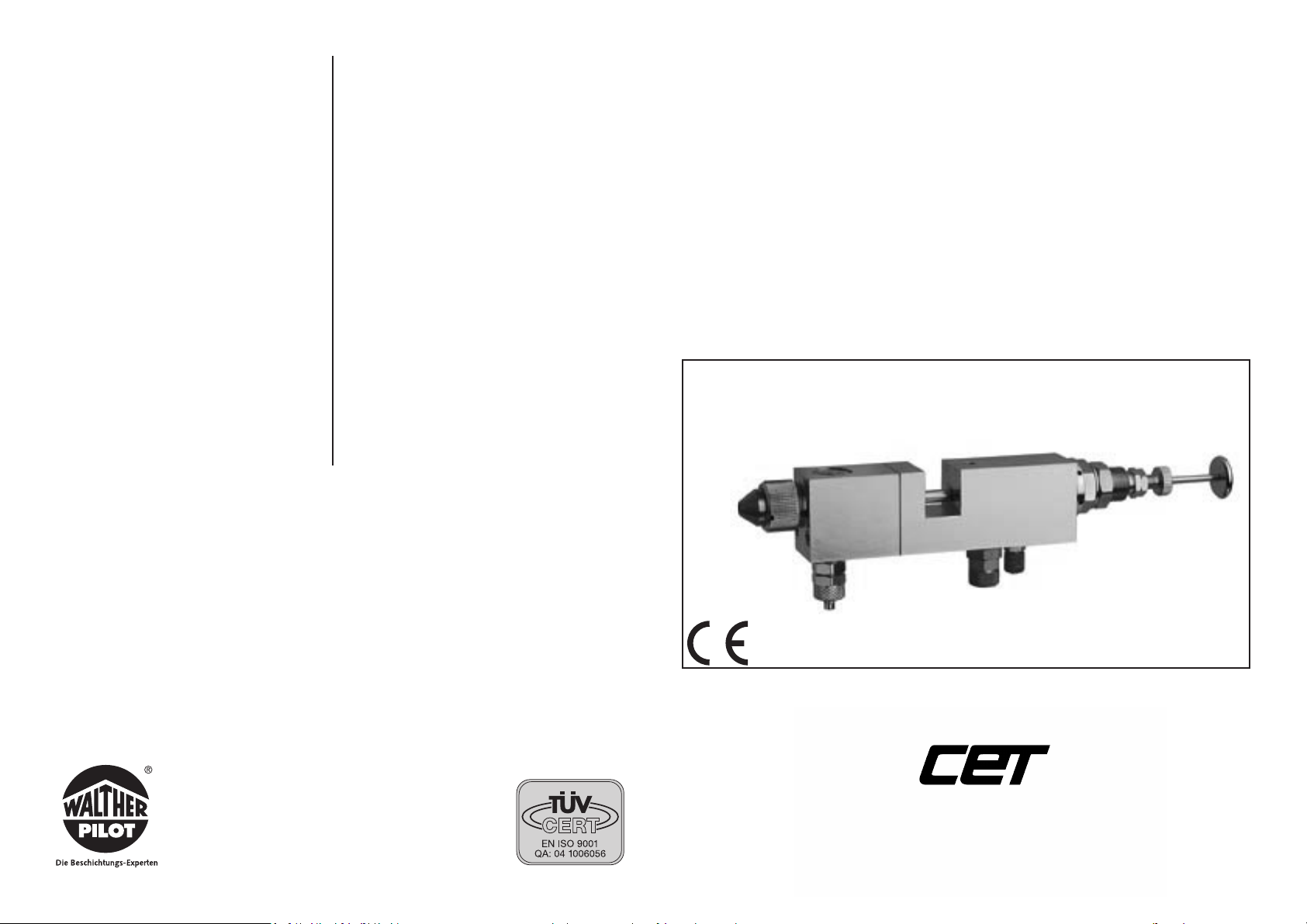
Signierpistole / Marking Gun
PPIILLOOTT SSiiggnniieerr 2200 335577
Membranausführung / Diaphragm - Version
Das WALTHER PILOTProgramm
• Hand-Spritzpistolen
• Automatik-Spritzpistolen
• Niederdruck-Spritzpistolen (System HVLP)
• Zweikomponenten-Spritzpistolen
• Materialdruckbehälter
• Drucklose Behälter
• Rührwerk-Systeme
• Airless-Geräte und Flüssigkeitspumpen
• Materialumlaufsysteme
• Kombinierte Spritz- und Trockenboxen
• Absaugsysteme mit Trockenabscheidung
• Absaugsysteme mit Naßabscheidung
• Pulversprühstände
• Trockner
• Zuluft-Systeme
• Atemschutzsysteme und Zubehör
The WALTHER PILOTProgramme
• Manual spray guns
• Automatic spray guns
• HVLP spray guns
• Two-component spray guns
• Pressure pots
• Pressureless containers
• Agitator systems
• Airless equipment and fluid pumps
• Material circulation systems
• Combined spraying and drying booths
• Exhaust extraction systems with dry filtering
• Exhaust extraction systems with wet filtering
• Powder spraying stands
• Dryers
• Air supply systems
• Breathing masks, breathing equipment and
accessories
WALTHER Spritz- und Lackiersysteme
Kärntner Str. 18-30 • 42327 Wuppertal
D-42306 Wuppertal
Telefon: 0202 / 787-0 • Telefax: 0202 / 787-217
www.walter-pilot.de • Email:info@walther-pilot.de
DISTRIBUTED BY COATING EQUIPMENT TECHNOLOGY, INC
PHONE: 586-210-0555
WEB: www.cetinc.com
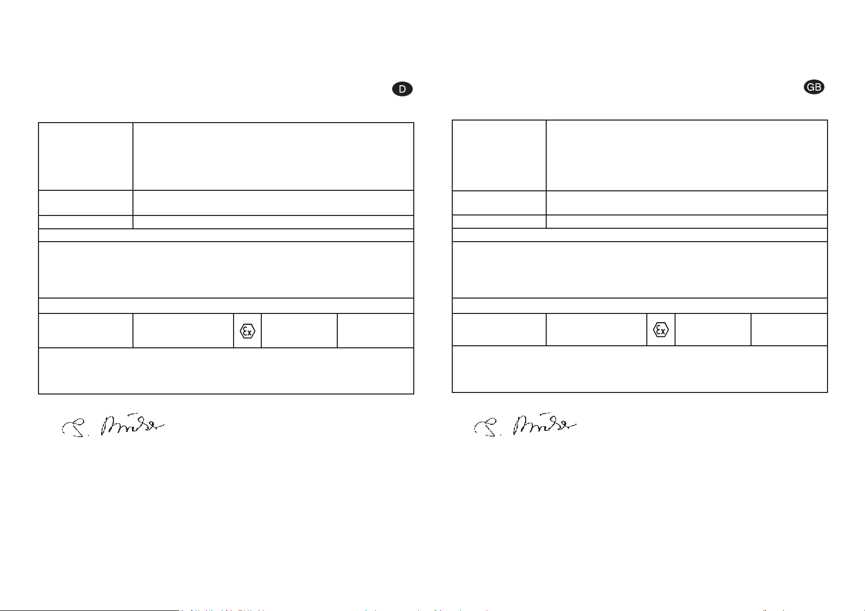
EG-Konformitätserklärung
Wir, der Gerätehersteller, erklären in alleiniger Verantwortung, daß das Produkt in der
untenstehenden Beschreibung den einschlägigen grundlegenden Sicherheits- und
Gesundheitsanforderungen entspricht. Bei einer nicht mit uns abgestimmten Änderung an dem Gerät oder bei einer unsachgemäßen Verwendung verliert diese
Erklärung ihre Gültigkeit.
Wuppertal,den 7. Juli 2003
Name: Torsten Bröker
Stellung im Betrieb: Leiter der Konstruktion und Entwicklung
Diese Erklärung ist keine Zusicherung von Eigenschaften im Sinne der Produkthaftung. Die Sicherheitshinweise der
Produktdokumentation sind zu beachten.
i.V.
Declaration of CE-Conformity
We, the manufacturers of the equipment, hereby declare under our sole responsibility
that the product(s) described below conform to the essential safety requirements.
This declaration will be rendered invalid if any changes are made to the equipment
without prior consultation with us.
Wuppertal, the 7th of July 2003
Name: Torsten Bröker
Position: Manager, Design and Development
This Declaration does not give assurance of properties in the sense of product liability. The safety instructions provided in the product documentation must be observed at all times.
Manufacturer WALTHER Spritz-und Lackiersysteme GmbH
Kärntner Str. 18-30
D-42327 Wuppertal
Tel.: 0202 / 787-0
Fax: 0202 / 787-217
www.walther-pilot.de • Email: info@walther-pilot.de
Type Designation Automatic Spray Gun PILOT Signier
PILOT Signier 20 357 (Marking - Diaphragm - Version) V 20 357
Intended purpose Processing of sprayable media
Applied Standards and Directives
EU-Machinery Directive 98 / 37 CE
94 / 9 EC (ATEX Directives)
DIN EN 292 Part 1
DIN EN 292 Part 2
DIN EN 1953
Specification according 94 / 9 / CE
Category 2 Part marking II 2 G c T 5
Tech.File,Ref.:
2408
Special remarks :
The named product is intended for installation in other equipment. Commissioning is prohibited until such time as the end product has been proved to conform to the provision of
the Directives 98 / 37 / CE.
i.V.
Hersteller WALTHER Spritz-und Lackiersysteme GmbH
Kärntner Str. 18-30
D-42327 Wuppertal
Tel.: 0202 / 787-0
Fax: 0202 / 787-217
www.walther-pilot.de • Email: info@walther-pilot.de
Typenbezeichnung Automatische Spritzpistole PILOT Signier
PILOT Signier 20357 (Signier - Membranausführung) V 20 357
Verwendungszweck Verarbeitung spritzbarer Materialien
Angewandte Normen und Richtlinien
EG-Maschinenrichtlinien 98 / 37 EG
94 / 9 EG (ATEX Richtlinien)
DIN EN 292 Teil 1
DIN EN 292 Teil 2
DIN EN 1953
Spezifikation im Sinne der Richtlinie 94 / 9 / EG
Kategorie 2 Gerätebezeichnung II 2 G c T 5
Tech.File,Ref.:
2408
Besondere Hinweise :
Das Produkt ist zum Einbau in ein anderes Gerät bestimmt. Die Inbetriebnahme ist so
lange untersagt, bis die Konformität des Endproduktes mit der Richtlinie 98 / 37 / EG
festgestellt ist.

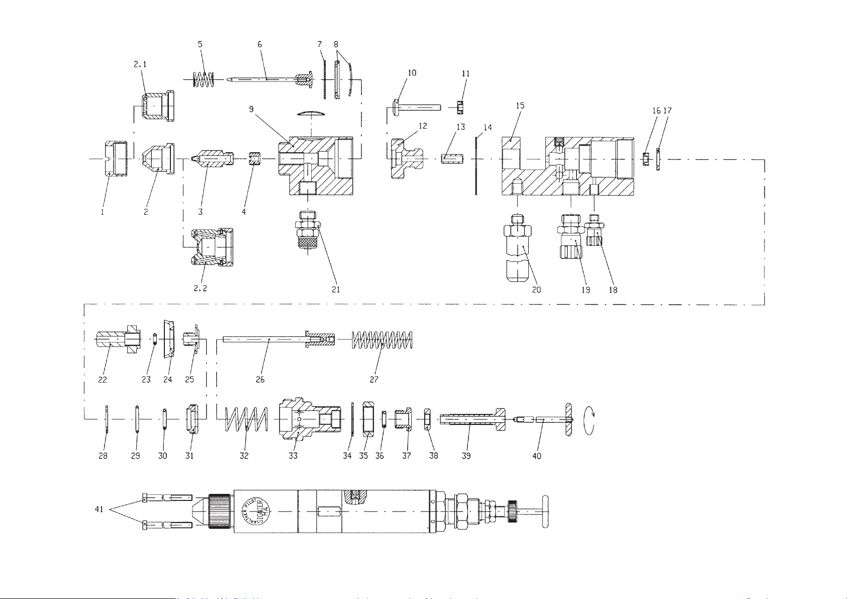
Parts list PILOT 20 357
Item Part number Description
1 V 20 335 15 . . 5 Air cap nut
2 V 20 336 34 . . 5* Round fan cap
2.1 V 20 336 44 . . 5* Small wide fan cap
2.2 V 20 336 50 . . 5* Large wide fan cap
3 V 20 336 23 . . 3* Material nozzle
4 V 20 355 25 004 Needle guide
5 V 20 355 17 003 Pressure spring
6 V 20 355 11 . . 3 Material needle
7 V 09 230 03 000 Diaphragm
8 V 20 355 15 000 Support washer
9 V 20 357 02 005 Front part
10 V 20 355 12 003 Pressure bar
11 V 09 220 25 000 Lip seal
12 V 20 355 03 004 Clamping sleeve
13 V 20 355 05 005 Coupling
14 V 09 002 44 000 Seal
15 V 20 357 01 005 Housing
16 V 09 220 25 000 Lip seal
17 V 09 230 04 000 Piston cylinder seal
18 V 66 100 03 561 Control air connection
19 V 66 100 02 027 Atomising air connection
20 V 20 357 03 003 Fastening bolt
21 V 66 100 02 127 Material connection
22 V 20 355 06 004 Piston
23 V 09 102 08 000 O - ring
24 V 09 210 11 000 Rubber packing ring
25 V 20 355 07 004 Piston screw
26 V 20 355 08 000 Piston rod
27 V 20 355 18 003 Needle spring
28 V 20 355 14 004 Washer
29 V 09 103 36 001 O - ring
30 V 09 102 09 001 O - ring
31 V 02 355 13 004 Piston guide
32 V 20 355 19 003 Piston spring
33 V 20 357 04 005 Spring bushing
34 V 20 666 06 000 Plain washer
35 V 20 660 04 003 Hexagonal nut
36 V 20 336 36 000 Clamping ring
37 V 10 501 06 000 Plug bushing
38 V 20 336 45 000 Locknut
39 V 20 355 20 005 Adjusting screw
40 V 20 336 38 390 Tension bar
41 V 20 355 21 003 Screw
* When ordering parts, please state the corresponding dimensions. We recommend that all
parts printed in bold type (wearing parts) are kept in stock.

Contents
1 General
1.1 Identification of Model Version
1.2 Proper use
1.3 Improper use
2 Technical description
3 Safety instructions
4 Using the spray gun
4.1 Connections for control air, atomising air and material
4.2 Spraying a test pattern
4.3 Changing the spray pattern
5 Retooling the spray gun
5.1 Changing the air cap
5.2 Changing the material nozzle
5.3 Changing the material needle
5.4 Changing the needle seal
6 Cleaning and maintenance
7 Troubleshooting
8 Technical data
1 General
1.1 Identification of Model Version
Model: Automatic Spray Gun PILOT Signier
Type: Marking Gun PILOT Signier 20 357 Diaphragm Version V 20 357
Manufacturer: WALTHER Spritz-und Lackiersysteme GmbH
Kärntner Str. 18-30
D-42327 Wuppertal
Tel.: 0202 / 787-0
Fax: 0202 / 787-217
www.walther-pilot.de • Email: info@walther-pilot.de
1.2 Proper use
The automatic spray gun PILOT Signier 20 357 must be used only for processing sprayable
materials, in particular:
• lacquers and paints
• grease, oil and anti-corrosion agents
• adhesives, grease, oil and anti-corrosion agents
• ceramic glazes
• stains
If you intend to spray materials that are not listed here, please contact WALTHER Spritz- und
Lackiersysteme GmbH, Wuppertal.
The sprayable materials must be sprayed only on workpieces or objects. The temperature of
the material to be sprayed must not exceed 80°C. The model PILOT WA 20 357 is not a
hand-held spray gun and must therefore be mounted in a suitable bracket.
Proper use of the spray gun also includes the fact that you have read, understood and
observed all information, advice and safety requirements presented in this instruction
manual.
This equipment complies with the explosion protection requirements of Directive 94 / 9 / EC
(ATEX 100a) for the explosion group, equipment category and temperature class indicated
on the type plate. When using the equipment, the requirements specified in these Operating
Instructions must be observed at all times. The technical data indicated on the equipment
rating plates and the specifications in the chapter "Technical Data" must be complied with at
all times and must not be exceeded. An overloading of the equipment must be ruled out.
The equipment may be used in potentially explosive atmospheres only with the authorisation
of the relevant supervisory authority.
The relevant supervisory authority or the operator of the equipment are responsible
for determining the explosion hazard (zone classification).
The operator must check and ensure that all technical data and the marking of the equipment in accordance with ATEX are compliant with the necessary requirements.
The operator must provide corresponding safety measures for all applications in which the
breakdown of the equipment might lead to danger to persons.
If any irregularities are observed while the equipment is in operation, the equipment must be
put out of operation immediately and WALTHER PILOT must be consulted.
Grounding / Equipotential Bonding
You must ensure that the spray gun is properly earthed (grounded) either separately or in
connection with the equipment with which it is being used (maximum resistance 10
6
Ω).
1.3 Improper use
The spray gun must not be used in any other way than as described above in the section
Proper use. Any other use is improper.
Improper use includes:
• spraying materials onto persons or animals.
• spraying liquid nitrogen.
2
1

2 Technical Description
The model PILOT WA 20 357 is operated automatically by compressed air and is controlled via a 3/2-way control valve. Hand-operated, foot-operated or solenoid-valve-operated
valves can be used for this purpose.
After actuating the 3/2-way control valve, the compressed air required for controlling enters
the cylinder chamber of the spray gun and opens the spraying air and material feed.
If the control air is interrupted by the 3/2-way valve, the compressed air in the cylinder
chamber is allowed to escape. The spring pressure of the piston and needle spring shuts
off the material feed to the material nozzle and then the spraying air feed.
The automatic spray gun as a recirculating version, e.g. for strongly settling materials, can
be integrated into a material circulation system. In addition, several automatic spray guns
can be supplied with the spraying material by the ring-shaped arrangement of the circulation piping.
3 Safety instructions
• The spray gun must be used only by trained and qualified persons.
• All relevant rules of safety and workers' safety regulations applicable in the country or
area of use must be fully observed.
• Observe the instructions given by the manufacturers of the spraying material and the
cleaning agents with regard to safety and proper use.
• Use the spray gun only in well-ventilated rooms. Fire, naked flames and smoking are prohibited within the working area.
• Always wear the regulation breathing masks, protective clothing and hearing protection
when using the spray gun.
• Exhaust air which contains particles must be kept away from the working area and operating personnel. Make sure that adequate exhaust extraction is provided.
• When spraying materials, keep your hands and other parts of the body away from the
pressurised nozzle of the spray gun.
• Do not direct the spray gun at persons or animals.
• Before carrying out maintenance or servicing, ensure that the air and material feed to the
spray gun have been de-pressurised.
•You must ensure that the spray gun is properly earthed (grounded) either separately or in
connection with the equipment with which it is being used (maximum resistance 10
6
Ω).
• After carrying out assembly and maintenance work, ensure that all nuts, bolts and screw
connections have been fully tightened.
• Use only original spare parts, since WALTHER can only guarantee safe and fault-free
operation for original parts.
For further information on the safe use of spraying equipment, please contact WALTHER
Spritz- und Lackiersysteme GmbH, Wuppertal
4 Using the spray gun
Before using the spray gun, ensure that the following conditions apply:
• The control air pressure is applied to the spray gun.
• The atomising air pressure is applied to the spray gun.
• The material pressure is applied to the spray gun.
4.1 Connections for control air, atomising air and material
• Connect the control air connector (via the 3/2-way valve) to the spray gun Item 18 and
set the control air pressure (min. 4.5 bar).
• Connect the atomising air connector to the air hose (filtered compressed air supply) and
to the atomising air connection of the spray gun Item 19.
• Switch on the compressed air and set the required atomising air pressure at the reducing
valve (max. 6 bar).
• Fill the pressure pot with the material to be sprayed and close the lid.
• Connect the material feed hose to the pressure pot or the pump and to the material
connection Item 21. Set the required material pressure (max. 6 bar).
• Open the material valve on the pressure pot.
4.2 Spraying a test pattern
A test spray pattern should always be made whenever:
• the spray gun is used for the first time.
• the spraying material is changed.
• the spray gun has been disassembled for maintenance or servicing.
The test pattern can be sprayed on a test workpiece, panel, cardboard or paper.
4.3 Changing the spray pattern
• Round-fan or wide-fan air caps are available
• The fan width can be varied by changing the atomising air
• The material flow rate is determined by the material pressure and the diameter of the
adjusting screw Item 33.
3
4

6 Troubleshooting5 Retooling the spray gun
Before retooling the spray gun, always ensure that the air supply and material supply to
the spray gun have been interrupted.
The combination of air cap, material nozzle and needle for a certain spraying material
forms a specially matched unit - the nozzle assembly. Always exchange the complete
nozzle assembly in order to maintain the desired spray pattern quality.
5.1 Changing the air cap
1. Unscrew the air cap nut and remove the air cap.
2. Installation takes place in reverse order.
5.2 Changing the material nozzle
1. Unscrew the air cap nut.
2. Remove the air cap.
3. Unscrew the material nozzle from the spray gun head.
4. Installation takes place in reverse order.
5.3 Changing the material needle
1. Unscrew the spray gun head from the body.
2. Release the front part and unscrew the clamping sleeve.
3. Remove the support washer and the diaphragm.
4. Withdraw the material needle together with the pressure spring.
5. Installation takes place in reverse order.
5.4 Changing the diaphragm
1. Unscrew the spray gun head from the body.
2. Release the front part and unscrew the clamping sleeve.
3. Remove the support washer and the diaphragm.
4. Installation takes place in reverse order.
5. When reinstalling the diaphragm, ensure that the teflon-coated side is pointing towards
the material channel.
Fault Cause Remedy
Gun drips
Gun does not open
Irregular or splattering spray
Gun sprays when switched off
Material leaks from the leakage hole
Material bubbling in material
container
Spray fan one-sided
Material needle or nozzle
dirty
Material needle or nozzle
damaged
Control air pressure too
low
Insufficient material in container
rubber packing ring Item
24 damaged
Diaphragm damaged
Atomising air is entering
the material container via
the material channel.
Material nozzle or air cap
not properly tightened
Air cap horn bore dirty
Remove and clean
Replace
Increase control air pressure
to min. 4.5 bar
Fill up with material (see
instructions from material
manufacturer)
Replace
Replace
Clean the parts, tighten or
replace
Remove and clean
5
6
Spray pattern test Fault Necessary adjustment
Swollen centre • Spray jet should be flatter
Swollen ends • Spray jet should be rounder
Coarse pearl effect • Increase atomising air pressure
Unduly thin paint
layer in centre
• Decrease atomising air pressure
Split centre
• Increase nozzle diameter
• Reduce atomising air pressure
• Increase material pressure
Split centre
• Decrease material pressure
• Increase atomising air pressure

7 Cleaning and maintenance
• To ensure that the spray gun functions properly and to maximise its service life, the spray
gun must be maintained, cleaned and lubricated regularly.
• Before carrying out any maintenance, ensure that the control air and atomising air as well
as the material feed are de-pressurised.
• Cleaning should be carried out after every colour and material change or according to the
degree of contamination.
• For cleaning the spray gun, use only those cleaning agents that are specified by the mate-
rial manufacturer and ensure that they do not contain any of the following components:
- halogenated hydrocarbons, e.g. 1,1,1-trichloroethane,
- methylene chloride,
- acids or acidic cleaning agents,
- paint strippers,
- regenerated solvents (cleaning thinners).
• Never immerse the whole spray gun in solvent or cleaning agent, as this could harm the
correct functioning of the gun.
• Do not use sharp or hard objects to clean the spray gun, as this might cause damage to
precision parts and impair the spraying result.
• WALTHER PILOT cannot accept any liability for damage caused by improper treatment of
the spray gun.
8 Technical data
Weight: 500 Gramm
Connections:
Atomising air: G 1/8 "
Control air: M 5
Material feed: G 1/8 "
Pressure range:
Control air pressure: min. 4,5 bar
Material pressure: max. 2 bar
Atomising air pressure: max. 6 bar
The noise level
is 83 dB (A)
Air consumption at:
1 bar Atomising air 1,2 m
3
/h
2 bar Atomising air 1,8 m3/h
3 bar Atomising air 2,4 m3/h
4 bar Atomising air 3,0 m3/h
5 bar Atomising air 3,6 m
3
/h
6 bar Atomising air 4,8 m3/h
Right to effect technical changes reserved.
7
 Loading...