

Page 1

Walther Systemtechnik GmbH – D 76726 Germersheim
Telefon: +49 (0)7274-7022-0 Telefax: +49 (0)7274-7022-91
http://www.walther-2000.de – info@walther-2000.de
Operating Manual
WALTHER Temperature Controller Bundle (WTRB)
Article Number: WTRB-x-x
IMPORTANT
Please read this manual carefully before the actual start of operation.
The device will only be used, maintained and repaired by personnel who are familiar with the
operating manual and also with the guiding regulations on workplace safety and accident prevention.
When used in or with other machines, the kit will not be operated if the machine does not
comply with the Machine Directive.
Page 2

Rev. 1.0
WALTHER Temperature Controller Bundle WTRB-x-x
Page 2 of 42
Walther Systemtechnik GmbH – D 76726 Germersheim
Telefon: +49 (0)7274-7022-0 Telefax: +49 (0)7274-7022-91
http://www.walther-2000.de – info@walther-2000.de
1 Table of Contents
1 Table of Contents ................................................................................................................... 2
2 General Information .............................................................................................................. 3
2.1 Scope of Delivery ................................................................................................................................... 3
2.2 Target Group of the Operating Manual .................................................................................................. 5
2.3 Contents of the Manual .......................................................................................................................... 5
2.4 List of Signs and Symbols ...................................................................................................................... 5
2.5 Warranty and Liability ............................................................................................................................. 5
2.6 Copyright ................................................................................................................................................ 5
3 Safety Information ................................................................................................................. 6
3.1 General Information ............................................................................................................................... 6
3.2 Basic Safety Instructions ........................................................................................................................ 6
3.3 Dangers from Using the Device ............................................................................................................. 6
3.4 Dangers from Residual Energy .............................................................................................................. 6
3.5 Correct Use ............................................................................................................................................ 7
3.6 Incorrect Use .......................................................................................................................................... 7
3.7 Personal Protective Equipment and Other Measures ............................................................................ 7
3.8 Required Qualification of Personnel....................................................................................................... 7
4 Transport ............................................................................................................................... 8
4.1 Packaging ............................................................................................................................................... 8
4.2 Transport ................................................................................................................................................ 8
4.3 Damages in Transport ............................................................................................................................ 8
4.4 Location of Set-up .................................................................................................................................. 8
5 Description of Product ............................................................................................................ 9
5.1 General Information ............................................................................................................................... 9
5.2 Electrical Installation / Start of Operation ............................................................................................. 11
5.3 Operation .............................................................................................................................................. 14
6 Technical Data / Installation Information ............................................................................. 16
6.1 Walther Temperature Controller WTR-x .............................................................................................. 16
6.2 Solid-state Relay WSSR-x-x ................................................................................................................ 22
7 Advanced Settings ............................................................................................................... 26
7.1 Concept of Levels................................................................................................................................. 26
7.2 Parameters ........................................................................................................................................... 28
7.3 Configuration (ConF) ............................................................................................................................ 29
7.4 Factory Configured Standard Parameters ........................................................................................... 37
8 Troubleshooting ................................................................................................................... 39
8.1 Error Messages .................................................................................................................................... 39
8.2 Self-Optimization .................................................................................................................................. 40
9 Service and Maintenance ..................................................................................................... 41
10 Spare Parts / Accessories .................................................................................................. 42
Page 3
Rev. 1.0
WALTHER Temperature Controller Bundle WTRB-x-x
Page 3 of 42
Walther Systemtechnik GmbH – D 76726 Germersheim
Telefon: +49 (0)7274-7022-0 Telefax: +49 (0)7274-7022-91
http://www.walther-2000.de – info@walther-2000.de
2 General Information
This operating manual is provided for a safe use and start of operation of our product series „Walther Temperature Controller Bundle (WTRB-x-x)“. The operating manual contains safety instructions for a smooth operation
as well as information on the function principle of the temperature controller. Above that, you will find information
and instructions for the mechanical and electrical installation. Please refer to Table 1 for an overview of all
available types and ordering numbers of the Walther Temperature Controller Bundles (WTRB).
Walther Temperature Controller Bundle (WTRB)
Ordering key
Version for 230 [VAC] heating
230AC
Solid-state Relay 230 [VAC] 6000 [mA]
6000
Version for 24 [VDC] heating
24DC
Solid-state Relay 24 [VDC] 3500 [mA]
3500
Solid-state Relay 24 [VDC] 6000 [mA]
6000
Solid-state Relay 24 [VDC] 12000 [mA]
12000
WTRB
- x
- x
Table 1: Ordering keys for the different versions of the Walther Temperature Controller Bundle (WTRB)
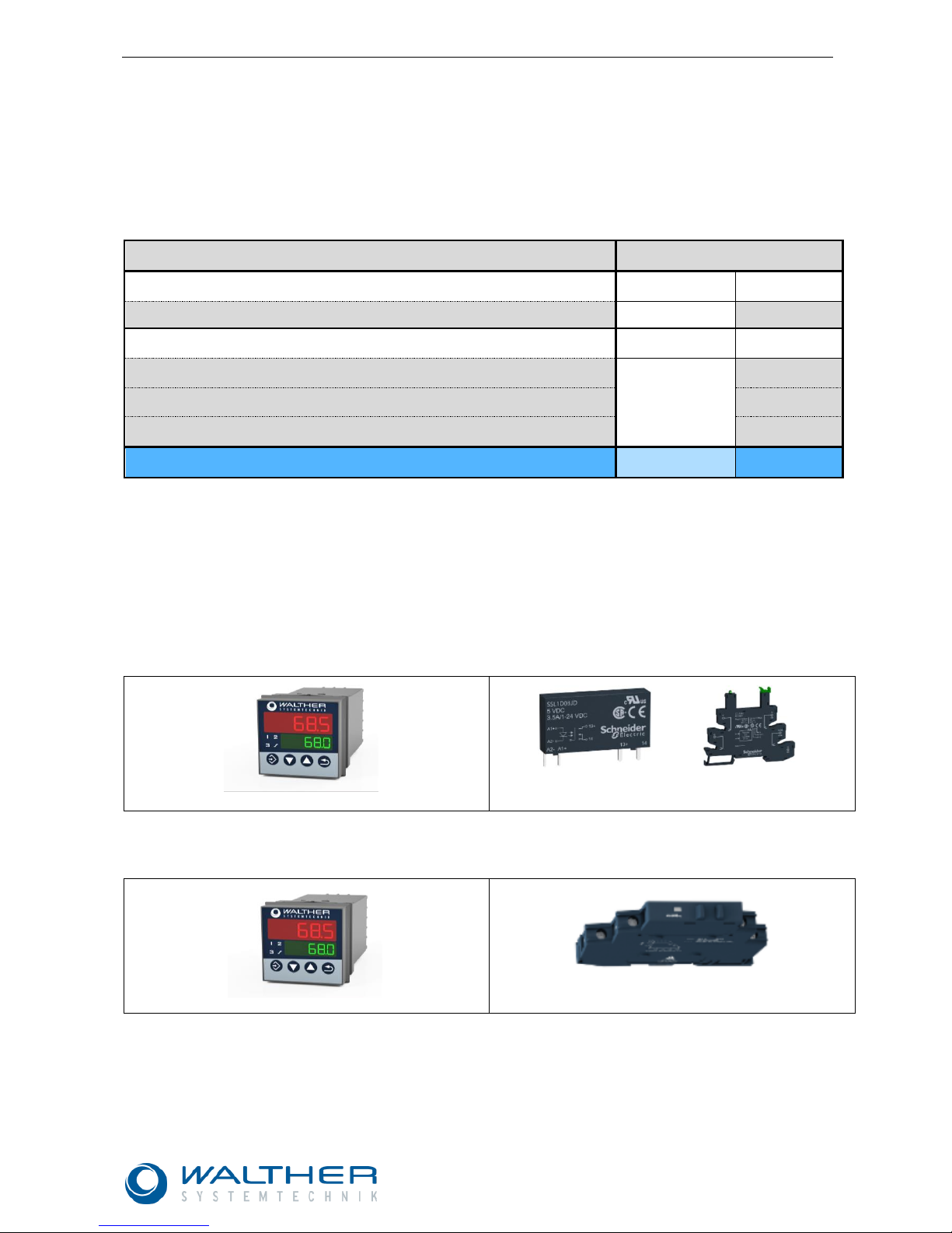
2.1 Scope of Delivery
The Walther Systemtechnik Temperature Controllers will be delivered as bundles, consisting of the temperature
controller itself and a solid-state relay (SSR) for top hat rail mounting. The scope of delivery varies depending
on the selected temperature controller bundle and is shown in the below figures:
Scope of Delivery for WTRB-24DC-3500
➀
Temp.Controller WTR-24DC
➁ Solid-state relay 24 [VDC] 3500 [mA] incl. mounting
base (WSSR-24DC-3500)
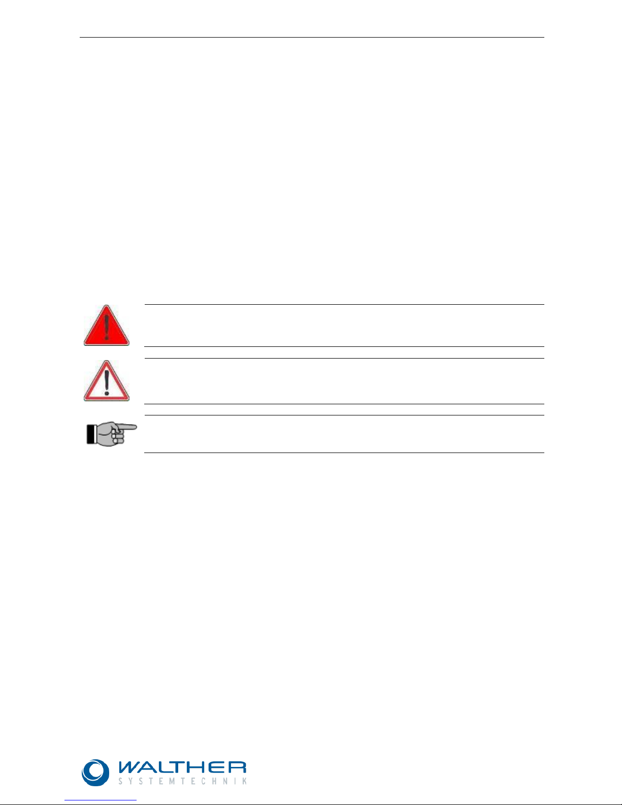
Scope of Delivery for WTRB-24DC-6000
➀
Temp.Controller WTR-24DC
➁ Solid-state relay 24 [VDC] 6000 [mA]
(WSSR-24DC-6000)
Page 4

Rev. 1.0
WALTHER Temperature Controller Bundle WTRB-x-x
Page 4 of 42
Walther Systemtechnik GmbH – D 76726 Germersheim
Telefon: +49 (0)7274-7022-0 Telefax: +49 (0)7274-7022-91
http://www.walther-2000.de – info@walther-2000.de
Scope of Delivery for WTRB-24DC-12000
➀
Temp.Controller WTR-24DC
➁ Solid-state relay 24 [VDC] 12000 [mA]
(WSSR-24DC-12000)
Scope of Delivery for WTRB-230AC-6000
➀ Temp.Controller WTR-230AC
➁ Solid-state relay 230 [VAC] 6000 [mA]
(WSSR-230AC-6000)
Page 5
Rev. 1.0
WALTHER Temperature Controller Bundle WTRB-x-x
Page 5 of 42
Walther Systemtechnik GmbH – D 76726 Germersheim
Telefon: +49 (0)7274-7022-0 Telefax: +49 (0)7274-7022-91
http://www.walther-2000.de – info@walther-2000.de
2.2 Target Group of the Operating Manual
➢ Operating personnel
➢ Maintenance personnel
2.3 Contents of the Manual
This Operating Manual contains information on:
➢ Safety
➢ Correct use
➢ Operation
➢ Service, maintenance and troubleshooting
2.4 List of Signs and Symbols
Symbols are used to indicate dangerous situations and specific behavior. These symbols are also used in this
operating manual. All warning, danger and information symbols describe situations which can be harmful to
persons, material or environment if rules are not followed.
The operating manual uses the following signs and symbols for dangers:
WARNING
Signals a potentially dangerous situation.
Death or severe injuries can follow, if you do not avoid this situation.
CAUTION
Signals a potentially dangerous situation.
Slight or minor injuries can follow, if you do not avoid this situation. This sign is also used
where damage to property is possible.
IMPORTANT
Indicates tips for usage and other particularly useful information.
No dangerous situation.
2.5 Warranty and Liability
According to the conditions laid down by the German Engineering Federation (VDMA), Walther Systemtechnik
GmbH has a guarantee of 12 months under normal European operating conditions on its own parts (spare parts
are excluded); or according to the conditions of the manufacturer.
This guarantee can only be granted by Walther Systemtechnik GmbH, if:
• the user has thorough knowledge of the content of this operating manual;
• the user follows the instructions and notes contained in this operating manual;
• the user does not rebuild or make changes on parts of the device without prior consent of Walther
Systemtechnik GmbH.
2.6 Copyright
We reserve the copyright for this operating manual. This operating manual is exclusively designated for the
operator and his personnel.
➢ Any copying – also only in part – or processing, or distribution or other use is strictly prohibited.
Page 6

Rev. 1.0
WALTHER Temperature Controller Bundle WTRB-x-x
Page 6 of 42
Walther Systemtechnik GmbH – D 76726 Germersheim
Telefon: +49 (0)7274-7022-0 Telefax: +49 (0)7274-7022-91
http://www.walther-2000.de – info@walther-2000.de
3 Safety Information
3.1 General Information
The construction of this device is according to the latest technology and is absolutely reliable. The individual
components as well as the complete device are continuously checked by our quality management team.
3.2 Basic Safety Instructions
Basic conditions for a safe handling and a failure-free operation of the device are:
Caution!!
• It is the customer’s responsibility that all relevant safety measures are followed.
• The device will only be used for the designated purpose.
• No changes will be made at the device. The customer carries the sole responsibility for
consequences resulting from failure to observe this guideline. Please contact Walther Systemtechnik GmbH for any desired modifications.
• Make sure that the device is always in a safe operational condition. Checks for proper
function or damages have to be performed by specialists on a regular basis. Dismounting
will only be made by authorized personnel and while using the operating manual. If requested, we will also offer trainings on the device in order to teach your personnel the
required knowledge.
• Disconnect the device from compressed air / grease supply for all maintenance tasks. All
lines and hoses have to be pressure-less.
• Check all lines, hoses and screwed joints regularly for leakages and apparent damages!
Repair damages immediately!
• Always make sure that the actual workstation and the device are clean and clearly arrange;
and this is routinely checked.
• Please observe the guiding rules and regulations for accident prevention at the workplace.
3.3 Dangers from Using the Device
The construction of this device and all assembly groups is according to the latest technology and is absolutely
reliable. However, there may be dangers for the user or third parties or other physical assets, if not used correctly.
Warning!! Use device only:
• for the designated purpose; and
• in a safe and operational condition.
• Immediately correct failures which can adversely affect safety and security!
3.4 Dangers from Residual Energy
Please instruct the operating personnel on the respective measures to be taken against the occurrence of mechanical, hydraulic, pneumatic and electric / electronic residual energies.
Page 7
Rev. 1.0
WALTHER Temperature Controller Bundle WTRB-x-x
Page 7 of 42
Walther Systemtechnik GmbH – D 76726 Germersheim
Telefon: +49 (0)7274-7022-0 Telefax: +49 (0)7274-7022-91
http://www.walther-2000.de – info@walther-2000.de
3.5 Correct Use
CAUTION
The device will only be used under the designated operating conditions as outlined in the offer
and the confirmation of order. It was exclusively designed for certain media in accordance with
the detailed description. Any different or further use will be regarded as incorrect. The manufacturer cannot be made liable for damages resulting from incorrect use.
Correct use also includes:
• Observing and following all instructions of this manual;
• Performing the inspection and routine maintenance tasks.
3.6 Incorrect Use
• Operating the device with insufficient knowledge about the operation, maintenance and care of the
device.
• Making changes, extensions or alterations on the device that may hamper its safety without the prior
consent of Walther Systemtechnik GmbH.
• Operating the device with defective safety installations or not properly attached or malfunctioning
safety devices.
• Using unsuitable materials.
• Handling the device while energized.
• Processing aggressive media (e.g. acids, alkaline solutions, detergents, chemicals, etc.) or media which
have not been approved in writing by the manufacturer.
• Making changes in the software of the controls
3.7 Personal Protective Equipment and Other Measures
• The operator company is responsible for providing the required personal protective gear.
• All safety devices and installations should be checked at regular intervals.
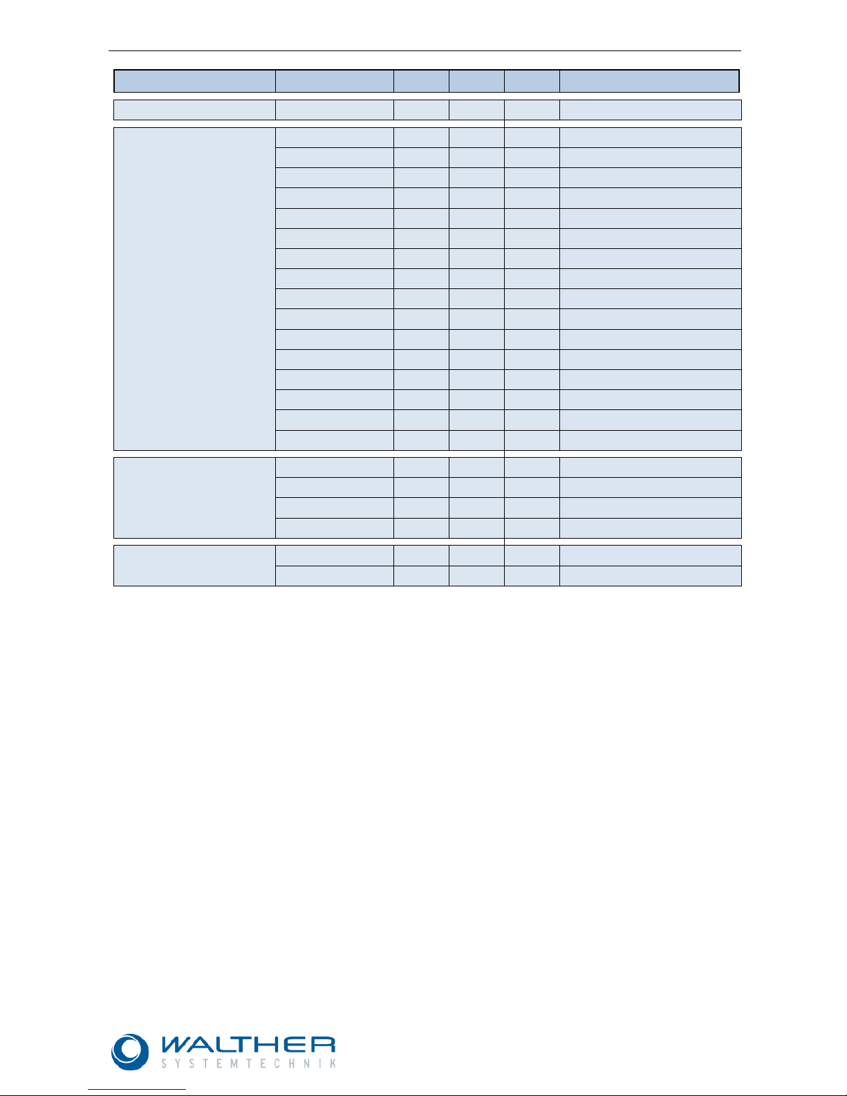
3.8 Required Qualification of Personnel
Only trained and instructed personnel may conduct work on the equipment.
The responsibilities of the personnel for assembly work, operation, repair work or maintenance work must be
clearly assigned to individuals!
Persons in training may work with the equipment under supervision of an experienced person only.
Personnel
Task
Instructed personnel
Personnel with technical qualification
Specialist
Supervisor
Packaging, transport
X - - - Commissioning
X X - Operation
X - Troubleshooting, general
X X - Troubleshooting, mechanical
- X - - Troubleshooting, electrical
- - X - Setting up
- X - - Maintenance
- X - - Repair
- X X
-
Taking out of service, storage,
disposal
- X X
-
Page 8

Rev. 1.0
WALTHER Temperature Controller Bundle WTRB-x-x
Page 8 of 42
Walther Systemtechnik GmbH – D 76726 Germersheim
Telefon: +49 (0)7274-7022-0 Telefax: +49 (0)7274-7022-91
http://www.walther-2000.de – info@walther-2000.de
4 Transport
4.1 Packaging
The device will be prepared by Walther Systemtechnik GmbH for a transport to the first destination.
The type of packaging depends on the individual mode of shipping. If not separately contracted, the packaging
is in accordance with the rules and regulations of Walther Systemtechnik GmbH. This rule is in accordance with
the Federal Association for Packaging HPE.
The packing unit will not be exposed to any additional strain. Packaging and contents will be protected against
any kind of humidity. The temperature for transport and storage will strictly range between –20°C and + 40°C.
4.2 Transport
The actual transport of the device and its individual parts requires special care in order to prevent damages from
external forceful impact or careless on- and off-loading. Depending on the mode of transportation, suitable
transport and load securing has to be selected. The device will be aligned and leveled by appropriate fastening
elements.
4.3 Damages in Transport
The following will be observed when the receiving checks reveal damages in transport:
• Contact the carrier (carrier, train etc.)
• Write a protocol of damages
• Contact the supplier
4.4 Location of Set-up
• All legal requirements for the mounting site should be clarified and fulfilled.
• Prior to installation of the equipment, the condition of the floor and the size of the surrounding space
should be checked to ensure safety of operation for both personnel and equipment. The installation must
be such that continuous operation at a high safety level is ensured.
• The installation of the equipment as well as commissioning or storage of the equipment must be conducted by specialists that are trained and made familiar with the equipment only.
• The equipment is designed for use in areas which are protected from climatic conditions.
• Operation or storage of the equipment in an aggressive or moist environment or outdoors may lead to
corrosion or other damage for which Walther Systemtechnik GmbH will not assume liability.
• All exposed parts and lines must be mounted as such that no injuries or damage can occur
• The minimum allowed space around the device will be closely observed.
Page 9
Rev. 1.0
WALTHER Temperature Controller Bundle WTRB-x-x
Page 9 of 42
Walther Systemtechnik GmbH – D 76726 Germersheim
Telefon: +49 (0)7274-7022-0 Telefax: +49 (0)7274-7022-91
http://www.walther-2000.de – info@walther-2000.de
5 Description of Product
5.1 General Information
Walther Temperature Controller Bundles (WTRB) are available for all heating plates and heating hoses from
Walther Systemtechnik GmbH. Based upon the selected heating technology product, Table 2 is your reference
guide for choosing the matching temperature controller bundle; the individual bundle contains a suitable temperature controller (WTR) and the adapted solid-state relay (WSSR). Please observe the following instructions
when using the Walther Temperature Controller Bundles (WTRB):
• The device is not suitable for installing in explosion-prone areas.
• Make sure that you follow the regulations of the DIN VDE 0100 "Construction of Low-Voltage Systems",
respectively the guiding state regulations (e.g. based upon the IEC 60364) when selecting the wiring
material, or during the installation, or for the electrical connection of the device.
• For maximum load, the lines have to be heat-resistant up to 80 °C.
• Only a trained and qualified technician will take care of the electrical connection.
• The device was designed for installation in switch cabinets or systems. The customer fuse protection
must not exceed 20 A. For all service / repair work, the device has to be completely disconnected from
current.
• Make sure that the load circuit will be protected for the maximum relay current; this will prevent a welding
of the output relay in case of a short circuit.
• The electromagnetic compatibility is accordance with standards and regulations mentioned under ‘tech-
nical data‘.
• Make sure that the lines for input, output and supply are physically separated and will not be laid paral-
lelly.
• Lines for sensors and interfaces will be twisted and shielded. Do not carry out near current-carrying
components or lines. Make sure that the shielding is grounded on one side.
• Do not connect other or additional users to the terminal plugs.
IMPORTANT
The WTR-x Temperature Controllers come with a standard configuration which matches most
of the heating elements of Walther Systemtechnik. The following chapters of this operating
manual refer to this standard configuration.
Page 10
Rev. 1.0
WALTHER Temperature Controller Bundle WTRB-x-x
Page 10 of 42
Walther Systemtechnik GmbH – D 76726 Germersheim
Telefon: +49 (0)7274-7022-0 Telefax: +49 (0)7274-7022-91
http://www.walther-2000.de – info@walther-2000.de
Product
Art.- No.
[V]
[A]
[W]
Temperature Cont. Bundle
Heating plates 24 [VDC]
HZP-x, etc.
24
1,0
25
WTRB-24DC-3500
Heating hoses 24 [VDC]
979524.001
24
2,5
60
WTRB-24DC-3500
979524.002
24
3,8
90
WTRB-24DC-6000
979524.003
24
1,9
45
WTRB-24DC-3500
979524.004
24
2,1
50
WTRB-24DC-3500
979524.007
24
7,5
180
WTRB-24DC-12000
979524.008
24
11,3
270
WTRB-24DC-12000
979524.009
24
5,0
120
WTRB-24DC-6000
979524.001M
24
2,5
60
WTRB-24DC-3500
979524.002M
24
3,8
90
WTRB-24DC-6000
979524.003M
24
1,9
45
WTRB-24DC-3500
979524.004M
24
2,1
50
WTRB-24DC-3500
979524.007M
24
7,5
180
WTRB-24DC-12000
979524.008M
24
11,3
270
WTRB-24DC-12000
979524.011M
24
3,2
76
WTRB-24DC-3500
979524.012M
24
5,6
135
WTRB-24DC-6000
979524.013M
24
5,6
135
WTRB-24DC-6000
Heating hoses 230 [VAC]
979524.102M
230
1,6
360
WTRB-230AC-6000
979524.103M
230
2,2
500
WTRB-230AC-6000
979524.104M
230
3,0
700
WTRB-230AC-6000
979524.100M
230
3,0
700
WTRB-230AC-6000
Heating pipes
979524.200
24
2,5
59
WTRB-24DC-3500
979524.201
24
2,5
59
WTRB-24DC-3500
Table 2: Reference guide for determining the correct Walther-Temperature Controller Bundle, based upon the selected heating technology
product.
Page 11
Rev. 1.0
WALTHER Temperature Controller Bundle WTRB-x-x
Page 11 of 42
Walther Systemtechnik GmbH – D 76726 Germersheim
Telefon: +49 (0)7274-7022-0 Telefax: +49 (0)7274-7022-91
http://www.walther-2000.de – info@walther-2000.de
5.2 Electrical Installation / Start of Operation
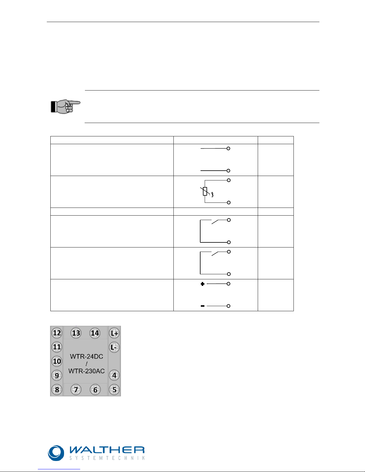
The Walther Temperature Controllers WTR-x have inlets and outlets, as listed in Table 3. Please refer to Figure
1 for the numbering of the connections. Please refer to model WTR-24DC or WTR-230AC for the voltage supply
at the marked pins (L+ / L- resp. L1 / N).
Pins 10 and 8 were configured as analog inputs for a PT100 2-wire resistance thermometer. The alarm outlets
for insufficient or excess temperature errors are integrated as make contacts at the pins 4 and 5, resp. 6 and 7.
The solid-state relay WSSR-x-x will be connected at the pins 13 and 14 of the logic output.
IMPORTANT
In order to also detect sensor errors and cable breaks at the alarm outputs, the make-contact
relays are permanently locked within the valid temperature range. If the preset temperature is
exceeded or fallen below, the contact will be interrupted (see also chapter 5.3.2 Limit Monitoring ).
Input
Symbol
Pin
Voltage supply
WTR-24DC: 24V DC
WTR-230AC: 230V AC
L1 (L+)
N (L-)
Analog input
Resistance thermometer PT100 2-wire
10
8
Output
Relay output (make contact) 1
Alarm output – error insufficient temperature
4
5
Relay outlet (make contact) 2
Alarm output - excess temperature error
6
7
Logic output (DC 0/12V)
Solid-state relay
13
14
Table 3: Overview of the inputs and outputs for the WTR-x and the pin assignment
Figure 1: View of back with terminal assignment for the WTR-24DC and WTR-230AC
AC/DC
Ux
Page 12

Rev. 1.0
WALTHER Temperature Controller Bundle WTRB-x-x
Page 12 of 42
Walther Systemtechnik GmbH – D 76726 Germersheim
Telefon: +49 (0)7274-7022-0 Telefax: +49 (0)7274-7022-91
http://www.walther-2000.de – info@walther-2000.de
5.2.1 Circuit Example
Figure 2 below shows you an example of connecting a 24 [VDC] heating device (e.g. a heating plate HZP-x)
to the components of a Walther Temperature Controller Bundle „WTRB-24DC-3500“.
CAUTION
This connection example only refers to the 24 [VDC] versions of the WTRB-x-x. Connecting
the 230 [VAC] models will not be similar. Pay special attention to the intended use and the
connection of the alarm outputs.
WTRB-24DC-3500
Figure 2: Sample connection for a WTRB-24DC-3500.
IMPORTANT
The Walther Systemtechnik heating elements come with a status LED which indicates the
heating operation. Pay close attention to a correct polarity of the heating elements in order to
guarantee a proper function.
Page 13

Rev. 1.0
WALTHER Temperature Controller Bundle WTRB-x-x
Page 13 of 42
Walther Systemtechnik GmbH – D 76726 Germersheim
Telefon: +49 (0)7274-7022-0 Telefax: +49 (0)7274-7022-91
http://www.walther-2000.de – info@walther-2000.de
5.2.2 Circuit Diagram
Figure 3: Circuit Diagram WTRB-24DC-3500
Page 14

Rev. 1.0
WALTHER Temperature Controller Bundle WTRB-x-x
Page 14 of 42
Walther Systemtechnik GmbH – D 76726 Germersheim
Telefon: +49 (0)7274-7022-0 Telefax: +49 (0)7274-7022-91
http://www.walther-2000.de – info@walther-2000.de
5.3 Operation
The Walther Systemtechnik Temperature Controllers come with a standard configuration which will only allow
changes in the preset temperature (SP1). The parameters of the analog input were pre-configured for a PT100
2-wire resistance thermometer. Please refer to chapter 5.3.2 for the pre-settings of the limit monitoring. Table 5
in section 7.4 provides an overview of the parameters of the standard configuration.
The controller parameters of the PID controller were pre-configured for the classic use with 24 [VDC]-heating
elements of Walther Systemtechnik GmbH.
IMPORTANT
If you are not satisfied with the control performance when using a heating element with the
pre-configured control parameters, you should change/adapt the PID control parameters.
Please refer to chapter 7 “Advanced Settings“ and 8.2 “Self-Optimization “.
5.3.1 Display and Operating Elements in the Standard Configuration
Use the buttons (B) and (C) for decreasing or increasing the desired temperature. The system will automatically accept and apply the set value.
(A) Change in level
(B) Decrease set value / previous parameter
(C) Increase set value / next parameter
(D) Function key / leave level
(E) Red 7-segment-display:
actual value
(F) Green 7-segment-display:
set value
(G) LED 1 ... 3: switch position for binary output (LED
lights up = output active)
Figure 4: Display and operating elements of the WTR-x-x.
When changing into the operating level OPr, you can switch between the following parameters with the buttons
(B) and (C) :
Symbol
Description
SP 1
Set value 1 (editable)
SP 2
Set value 2 (not used)
InP 1
Measured value at analog input resistance thermometer
Y
Current output level (0-100 [%])
Table 4: Available parameters in the operator level OPr
69.5
70
(A)
(B)
(C)
(D)
(G)
(E)
(F)
Page 15

Rev. 1.0
WALTHER Temperature Controller Bundle WTRB-x-x
Page 15 of 42
Walther Systemtechnik GmbH – D 76726 Germersheim
Telefon: +49 (0)7274-7022-0 Telefax: +49 (0)7274-7022-91
http://www.walther-2000.de – info@walther-2000.de
5.3.2 Limit Monitoring
One alarm output for excess and one alarm output for insufficient temperature have been pre-configured. They
were set at ± 1 [°C] from the currently set desired value (SP1). In order to prevent malfunctions from broken
cables, a permanent signal is transferred to the superordinate control unit. If the preset value at the WTR is
exceeded or fallen short by 1°C, the individual alarm output drops as a signal for the superordinate control unit
(Signal at LOW). The alarm signal is turned off (Signal at HIGH) once the set value range has been reached
again. If the currently measured, actual temperature is within the preset tolerance range of ± 1 [°C], HIGH will
be indicated for both alarm outputs.
The hysteresis (HySt) for error signal is factory-set at ±1 [°C] symmetrically to the limit value of the insufficient
temperature (UT) or excess temperature (OT). If the temperature rises or falls back into these limits, the respective signal will be given. Please refer to Figure 5 for the signal curves of the two alarm outlets of the WTR-x.
Signal at alarm output 1
Used for issuing an error signal
for insufficient temperature (deviation AL -1°C to set value SP1)
Signal at alarm output 2
Used for issuing an error signal
for excess temperature (deviation
AL +1°C to set value SP1)
Figure 5: Signal curves of the alarm outlets of the WTR-x.
1
0
SP1
Temp.
AL
HySt
UT
1
0
SP1
Temp.
AL
HySt
OT
Page 16

Rev. 1.0
WALTHER Temperature Controller Bundle WTRB-x-x
Page 16 of 42
Walther Systemtechnik GmbH – D 76726 Germersheim
Telefon: +49 (0)7274-7022-0 Telefax: +49 (0)7274-7022-91
http://www.walther-2000.de – info@walther-2000.de
6 Technical Data / Installation Information
Section 6.1 below provides installation instructions and dimensions for the mechanical mounting of the Walther
Temperature Controllers WTR-24DC and WTR-230AC, as well as the applying technical data. Please refer to
section 6.2 for the technical data and dimensions of the solid-state relay WSSR-x-x.
6.1 Walther Temperature Controller WTR-x
Both types (WTR-24DC and WTR-230AC) have the same dimensions and identical steps for mounting. Figure
6 shows the outside dimensions. For mounting on a switchboard, a square cut with 45
+0,6
[mm] side length is
required.
Figure 6: Dimensions of the WTR-x
Figure 7 shows you how to mount. Insert the device from the
front into the opening in the switchboard, and make sure that
the gasket fits properly (1). From the back of the switchboard,
place the fastening frame on the device and push the springs
against the back of the switchboard (2) until the latches click
into the designated grooves and the device is properly fixed.
Figure 7: Mounting the WTR
Switchboard cut 45
+0,6
x 45
+0,6
Units [mm]
Page 17

Rev. 1.0
WALTHER Temperature Controller Bundle WTRB-x-x
Page 17 of 42
Walther Systemtechnik GmbH – D 76726 Germersheim
Telefon: +49 (0)7274-7022-0 Telefax: +49 (0)7274-7022-91
http://www.walther-2000.de – info@walther-2000.de
6.1.1 Technical Information for WTR-24DC
Input Resistance Thermometer (Pins 8; 9; 10)
Description
Measured range
Measuring
accuracy
Ambient temperature influence
PT100 2-wire connection according to
DIN EN 60751
-200 … +650 [°C]
≤ 0,4 [%]
≤ 100 [ppm/K]
Sensor line resistance: max. 30 [Ω] per line with a three-wire circuit
Measured current: PT100 ca. 1 [mA]
Line balancing:
For a two-wire circuit, a line balancing can be performed through a correction of the actual value (see
chapter 7.3 Configuration (ConF)).
Outputs
Relay (make contact)
(Pins 4/5 and 6/7)
Switch capacity/
Contact lifetime
max. 3 [A[ at 230 [VAC[ resistive load
150.000 switches at nominal load
350.000 switches at 1 [A[
310.000 switches at 1 [A[ and cos ϕ > 0,7
Logic output for SSR
(Pins 13/14)
0/14 [V] 20 [mA] max.
Controller
Controller type
Two-point controller, three-point controller, permanent controller
Controller structure
P/PI/PD/PID
Scan time
250 [ms]
A/D convertor
Resolution 16 Bit
Timer
Accuracy
0,8 [%] ± [ppm/K] ± 250 [ms]
Electrical Data
Voltage supply (power supply)
AC/DC 20 … 30 [V], 48 … 63 [Hz]
Electrical safety
According to DIN EN 61010, Part 1
Overvoltage Category III, Degree of Contamination 2
Power consumption
max. 14 VA
Electrical connection /
Wire diameter /
Tightening torque
From back with screw terminal; with wire
end ferrule (pipe shape), open cable lug or
terminal pin, fine-stranded wire 0,25 ... 1,5
[mm²] 0,5 [Nm]
Electromagnetic compatibility – emitted interference – interference immunity
According to DIN EN 61326-1 Class A – for
industrial use only – industrial requirement
Setup interface
USB socket, type Mini-B 5-poles
Page 18

Rev. 1.0
WALTHER Temperature Controller Bundle WTRB-x-x
Page 18 of 42
Walther Systemtechnik GmbH – D 76726 Germersheim
Telefon: +49 (0)7274-7022-0 Telefax: +49 (0)7274-7022-91
http://www.walther-2000.de – info@walther-2000.de
Requirements for wire end ferrules and cable lug
Type of housing
Plastic housing for mounting in switchboard
according to DIN IEC 61554 (use indoors)
Dimensions (Front)
48 [mm[ x 48 [mm[
Switchboard cut/opening
45 [mm] x 45 [mm]
Minimum distance horizontal / vertical
11 [mm] / 30 [mm] (65 [mm] with USB cable
Mounting depth
max. 95
[mm]
Mounting
depth
max. 95 [mm]
Ambient / storage temperature range
Climate resistance
rel. humidity <
90[%]
annual
average
without
condensation
Climate
resistance
rel. humidity < 90[%] annual average without
condensation
Set-up altitude
max. 2000 [m] above NN
Operating position
Any
Protection type
According to DIN EN 60529, front IP 65,
back IP 20
Weight (fully equipped)
ca. 150 [g]
Type of housing
Plastic housing for mounting in switchboard
according to DIN IEC 61554 (use indoors)
Dimensions (Front)
48 [mm[ x 48 [mm[
Switchboard cut/opening
45 [mm] x 45 [mm]
Minimum distance horizontal / vertical
11 [mm] / 30 [mm] (65 [mm] with USB cable
Mounting depth
max. 95 [mm]
Ambient / storage temperature range
-5 ... +55 [°C] / -40 ... +70 [°C]
Climate resistance
rel. humidity < 90[%] annual average without
condensation
Certification / Mark of Conformity
Mark of conformity c UL us of the verifying authority Underwriters Laboratories with certificate number
E201387 based upon test principles UL 61010-1 CAN/CSA C22.2 No. 61010-1
Page 19

Rev. 1.0
WALTHER Temperature Controller Bundle WTRB-x-x
Page 19 of 42
Walther Systemtechnik GmbH – D 76726 Germersheim
Telefon: +49 (0)7274-7022-0 Telefax: +49 (0)7274-7022-91
http://www.walther-2000.de – info@walther-2000.de
6.1.2 Technical Information for WTR-230AC
Input Resistance Thermometer
Description
Measured range
Measuring
accuracy
Ambient temperature influence
PT100 2-wire connection
according to DIN EN
60751
-200 … +650 [°C]
≤ 0,4 [%]
≤ 100 [ppm/K]
Sensor line resistance: max. 30 [Ω] per line with a three-wire circuit
Measured current: PT100 ca. 1 [mA]
Line balancing:
For a two-wire circuit, a line balancing can be performed through a correction of the actual value (see
chapter 7.3 Configuration (ConF)).
Outputs
Relay (make contact)
(Pins 4/5 and 6/7)
Switch capacity/
Contact lifetime
max. 3 [A[ at 230 [VAC[ resistive load
150.000 switches at nominal load
350.000 switches at 1 [A[
310.000 switches at 1 [A[ and cos ϕ > 0,7
Logic output for SSR (Pins
13/14)
0/14 [V] 20 [mA] max.
Controller
Controller type
Two-point controller, three-point controller, permanent controller
Controller structure
P/PI/PD/PID
Scan time
250 [ms]
A/D convertor
Resolution 16 Bit
Timer
Accuracy
0,8 % ± [ppm/K] ± 250 [ms]
Electrical Data
Voltage supply (power supply)
AC 110 … 240 [V] +10/-15 [%], 48 … 63
[Hz]
Electrical safety
According to DIN EN 61010, Part 1
Overvoltage Category III, Degree of Contamination 2
Power consumption
max. 14 VA
Electrical connection /
Wire diameter /
Tightening torque
From back with screw terminal; with wire
end ferrule (pipe shape), open cable lug or
terminal pin, fine-stranded wire 0,25 ... 1,5
[mm²] 0,5 [Nm]
Electromagnetic compatibility – emitted interference – interference immunity
According to DIN EN 61326-1 Class A – for
industrial use only – industrial requirement
Setup interface
USB socket, type Mini-B 5-poles
Page 20

Rev. 1.0
WALTHER Temperature Controller Bundle WTRB-x-x
Page 20 of 42
Walther Systemtechnik GmbH – D 76726 Germersheim
Telefon: +49 (0)7274-7022-0 Telefax: +49 (0)7274-7022-91
http://www.walther-2000.de – info@walther-2000.de
Requirements for wire end ferrules and cable lug
Wire end ferrule
Pie shape, without plastic sleeve according
to DIN 46228 Part 1,
with plastic sleeve according to DIN 46228
Part 4
Cable lug
Open crimp terminal, similar to DIN 46237
for closed crimp terminal
Pin terminal
According to DIN 46231
For UL applications
Use of cable lugs and wire end ferrules according to
UL 486A-B (UL listed or recognized)
Housing
Type of housing
Plastic housing for mounting in switchboard
according to DIN IEC 61554 (use indoors)
Dimensions (Front)
48 [mm[ x 48 [mm[
Switchboard cut/opening
45 [mm] x 45 [mm]
Minimum distance horizontal / vertical
11 [mm] / 30 [mm] (65 [mm] with USB cable
Mounting depth
max. 95 [mm]
Ambient / storage temperature range
-5 ... +55 [°C] / -40 ... +70 [°C]
Climate resistance
rel. humidity < 90[%] annual average without
condensation
Set-up altitude
max. 2000 [m] above NN
Operating position
Any
Protection type
According to DIN EN 60529, front IP 65,
back IP 20
Weight (fully equipped)
ca. 150 [g]
Certification/Mark of Conformity
Mark of conformity c UL us of the verifying authority Underwriters Laboratories with certificate number
E201387 based upon test principles UL 61010-1 CAN/CSA C22.2 No. 61010-1
Page 21

Rev. 1.0
WALTHER Temperature Controller Bundle WTRB-x-x
Page 21 of 42
Walther Systemtechnik GmbH – D 76726 Germersheim
Telefon: +49 (0)7274-7022-0 Telefax: +49 (0)7274-7022-91
http://www.walther-2000.de – info@walther-2000.de
6.1.3 Galvanic Isolation WTR-x
Figure 8 shows you the galvanic isolation for Walther Temperature Controllers.
(1) Analog input
(2) Binary input
(3) Setup interface (USB)
(4) Supply voltage
(5) RS485 – interface
(6) Analog output
(7) Relay outputs
(8) Logic outputs
Figure 8: Galvanic isolation of the WTR-x
2300V
AC
30 V AC
50 V DC
2300 V
AC
30 V AC
50 V DC
(7)
(1)
(3)
(2)
(6)
(5)
(4)
(8)
Page 22

Rev. 1.0
WALTHER Temperature Controller Bundle WTRB-x-x
Page 22 of 42
Walther Systemtechnik GmbH – D 76726 Germersheim
Telefon: +49 (0)7274-7022-0 Telefax: +49 (0)7274-7022-91
http://www.walther-2000.de – info@walther-2000.de
6.2 Solid-state Relay WSSR-x-x
6.2.1 Technical Information for WSSR-24DC-3500
Main Features
Product or type of component
Solid-state relay
Number of channels
1
Number of mains phases
1 phase
Additional Characteristics
Mounting bracket
Base
Rated current [In]
3,5 [A]
Outlet voltage
1...24 [VDC]
Control circuit voltage
3...12 [VDC]
Setup and type of connection
1 S
Capacity unbalance
<= 1,5 [pF] for inlet / outlet
Minimal switch voltage
3 [VDC] turn-on
Maximum switch voltage
1 [VDC] turn-off
Inlet current limits
10 [mA]
Solid shaft outlet type
DC contactor / Mosfet output
Load current
0,001...3,5 [A]
Absolute maximum voltage
30 [V]
Surge current
<= 9 [A] for 10 [ms]
Drop in voltage
<= 0,5 [V] turned on
Leakage current
<= 0,001 [mA] turned off
Reaction time
0,12 [ms] turning on
0,1 [ms] turning off
Overvoltage category
III
Width
5 [mm[
Height
28 [mm]
Depth
15 [mm]
Product weight
0,0041 [kg]
SSL1D03JD
13+
A1+
LOAD 1…24VDC/3,5A
INPUT 3…12VDC
A2-
14
1 2 4
3
Solid-state relay
Base
Page 23

Rev. 1.0
WALTHER Temperature Controller Bundle WTRB-x-x
Page 23 of 42
Walther Systemtechnik GmbH – D 76726 Germersheim
Telefon: +49 (0)7274-7022-0 Telefax: +49 (0)7274-7022-91
http://www.walther-2000.de – info@walther-2000.de
6.2.2 Technical Information for WSSR-24DC-6000
Main Features
Product or type of component
Solid-state relay
Number of channels
1
Number of mains phases
1 phase
Additional Characteristics
Mounting bracket
Symmetrical DIN rail
Rated current [In]
6 A
Outlet voltage
1...60 [VDC]
Control circuit voltage
4...32 [VDC]
Setup and type of connection
1 S
Starting torque
Inlets : 0,5...0,8 [N]
Outlets : 0,5...0,8 [N]
Connections – clamps
Screw terminal : 1 x 0,3...1 x 1,5 [mm²],
(AWG 22...AWG 16) for inputs
Screw terminal : 1 x 0,3...1 x 2,5 [mm²],
(AWG 22-AWG 14) for outputs
Capacity unbalance
<= 10 [pF] for inlet / outlet
Insulation resistance
1000 [MΩ] at 500 [VDC]
Local signaling
LED green for input status
Minimum switch voltage
4 [VDC] turn-on
Maximum switch voltage
10 [VDC] turn-off
Inlet current limits
8...11 [mA]
Solid shaft outlet type
Mosfet outlet / DC contactor
Load current
0,0025...6 [A]
Absolute maximum voltage
60 [V]
Surge current
<= 60 [A] for 10 [ms]
Drop in voltage
<= 0,6 [V] turned on
Resistance
0,1 [Ω] turned on
Leakage current
<= 0,1 [mA] turned off
Reaction time
0,6 [ms] turning on
0,3 [ms] turning off
Overvoltage category
III
Width
11 [mm]
Height
90,3 [mm]
Depth
83,7 [mm]
Product weight
0,05 [kg]
SSM1D26BD
11/13+
A2
LOAD 1…60VDC/6A
INPUT 4…32VDC
A1
14
1 2 4
3
Page 24

Rev. 1.0
WALTHER Temperature Controller Bundle WTRB-x-x
Page 24 of 42
Walther Systemtechnik GmbH – D 76726 Germersheim
Telefon: +49 (0)7274-7022-0 Telefax: +49 (0)7274-7022-91
http://www.walther-2000.de – info@walther-2000.de
6.2.3 Technical Information for WSSR-24DC-12000
Main Features
Product or type of component
Solid-state relay
Number of channels
1
Number of mains phases
1 phase
Additional Characteristics
Mounting bracket
Symmetrical DIN rail
Rated current [In]
12 [A]
Outlet voltage
1...60 [VDC]
Control circuit voltage
4...32 [VDC]
Setup and type of connection
1 S
Starting torque
Inlets : 0,5...0,8 [N]
Outlets : 0,5...0,8 [N]
Connections – clamps
Screw terminals : 1 x 0,3...1 x 1,5 [mm²],
(AWG 22...AWG 16) for inputs
Screw terminals : 1 x 0,3...1 x 2,5 [mm²],
(AWG 22-AWG 14) for outputs
Capacity unbalance
<= 10 [pF] for inlet / outlet
Insulation resistance
1000 [MΩ] at 500 [VDC]
Local signaling
LED green for input status
Minimum switch voltage
4 [VDC] turn-on
Maximum switch voltage
1 [VDC] turn-off
Inlet current limits
9...11 [mA]
Solid shaft outlet type
DC contactor / Mosfet outlet
Load current
0,0025…12 [A]
Absolute maximum voltage
60 [V]
Surge current
<= 100 [A] for 10 [ms]
Drop in voltage
<= 0,5 [V] turned on
Resistance
0,045 [Ω] turned on
Leakage current
<= 0,1 [mA] turned off
Reaction time
0,6 [ms] turning on
0,3 [ms] turning off
Overvoltage category
III
Width
18 [mm]
Height
90,3 [mm]
Depth
83,7 [mm]
Product weight
0,09 [kg]
SSM1D212BD
11/13+
A2
LOAD 1…60VDC/12A
INPUT 4…32VDC
A1
14
1 2 4
3
Page 25

Rev. 1.0
WALTHER Temperature Controller Bundle WTRB-x-x
Page 25 of 42
Walther Systemtechnik GmbH – D 76726 Germersheim
Telefon: +49 (0)7274-7022-0 Telefax: +49 (0)7274-7022-91
http://www.walther-2000.de – info@walther-2000.de
6.2.4 Technical Information for WSSR-230AC-6000
Main Features
Product or type of component
Solid-state relay
Number of channels
1
Number of mains phases
1 phase
Additional Characteristics
Mounting bracket
Symmetrical DIN rail
Rated current [In]
6 [A]
Outlet voltage
24...280 [VAC]
Control circuit voltage
4...32 [VDC]
Setup and type of connection
1 S
Starting torque
Inlets : 0,5...0,8 [N]
Outlets : 0,5...0,8 [N]
Connections – clamps
Screw terminals : 1 x 0,3...1 x 1,5 [mm²],
(AWG 22...AWG 16) for inputs
Screw terminals : 1 x 0,3...1 x 2,5 [mm²],
(AWG 22-AWG 14) for outputs
Capacity unbalance
<= 10 [pF] for inlet / outlet
Insulation resistance
1000 [MΩ] at 500 [VDC]
Local signaling
LED green for input status
Minimum switch voltage
4 [VDC] turn-on
Maximum switch voltage
1 [VDC] turn-off
Inlet current limits
8...11 [mA]
Solid shaft outlet type
Zero-voltage switching, thyristor output
Load current
0,00015...6 [A]
Absolute maximum voltage
600 [V]
Surge current
<= 285 [A] for 16.6 [ms]
<= 300 [A] for 20 [ms]
Motor performance (HP)
0,16 [hp] at 40 [°C] 240 [VAC]
Drop in voltage
<= 1,3 [V] turned on
Leakage current
<= 0,1 [mA] turned off
Reaction time
0,5 cycles turning on
0,5 cycles turning off
Overvoltage category
III
Width
11 [mm]
Height
90,3 [mm]
Depth
83,7 [mm]
Product weight
0,05 [kg]
SSM1A16BD
-K17
L1
A1+
LOAD 24…280VAC/6A
INPUT 4…32VDC
A2
T1
1 2 4
3
Page 26

Rev. 1.0
WALTHER Temperature Controller Bundle WTRB-x-x
Page 26 of 42
Walther Systemtechnik GmbH – D 76726 Germersheim
Telefon: +49 (0)7274-7022-0 Telefax: +49 (0)7274-7022-91
http://www.walther-2000.de – info@walther-2000.de
7 Advanced Settings
IMPORTANT NOTE!
Only make changes in the “Advanced Settings“ if the standard factory settings do not produce
satisfactory controlling results. As a rule, changes in the “Advanced Settings” should only be
made by trained and qualified technicians with experience in control technology.
7.1 Concept of Levels
Locking of Levels
(the factory settings only allow access to the operating level)
1. Press (A) and (B) at the same time (>5 s)
2. Press (A) (display is blinking)
3. Enter code with (B) or (C)
4. Press (D) for returning to normal display
Code
Operator level
Parameter level
Configuration level
0
Free
Free
Free
1
Free
Free
Locked
2
Free
Locked
Locked
3
Locked
Locked
Locked
(H) Programming / one level lower
(I) Decrease value / previous parameter
(J) Increase value / next parameter
(K) Function key / leave level
(L) Red 7-segment-display (factory set: actual value);
four digits, configurable decimal place (automatic
adjustment when display capacity is reached)
(M) Green 7-segment-display (factory set: desired
value);
four digits, configurable decimal place; also showing level and parameter symbols
(N) LED 1 ... 3: switch position binary output (LED
lights up = outlet active)
(1) Changing from normal display into levels
(2) Changing between levels
(3) Change within operator level (desired values, process val-
ues, timer value and times)
(4) Change to parameter level (control parameters)
(5) Change to configuration level (analog input, controller,
ramp function, limit value monitoring, timer, outputs, binary
functions, display and operation, interface)
(6) Return to normal display
(10) Navigation principle:
(11) – one level lower
(12) – next parameter / increase value
(13) – previous parameter / decrease value
(14) – go one level back
24.98
54.32
(2)
(1)
(3)
(4)
(5)
(6)
OPr
PArA
ConF
>2s
(11)
(14)
(12)
(13)
(10)
If you do not press a button for 10 [s] (factory set), the device returns to normal display. This duration can be configured.
.
69.5
70
(A)
(B)
(C)
(D)
(H)
(G)
(E)
(F)
Page 27

Rev. 1.0
WALTHER Temperature Controller Bundle WTRB-x-x
Page 27 of 42
Walther Systemtechnik GmbH – D 76726 Germersheim
Telefon: +49 (0)7274-7022-0 Telefax: +49 (0)7274-7022-91
http://www.walther-2000.de – info@walther-2000.de
Entering values
When entering values in the actual levels, the lower display shows you the symbol of the parameter,
(1) Select parameter (lower display -
green)
(2) Change value (upper display - red)
(3) Parameter blinking
Entering times
Time values are displayed with a decimal point in the middle and to the right. Time units can be configured.
(1) Select parameter (lower display -
green)
(2) Change value (upper display - red)
(3) Parameter blinking
Procedure
1.
Select parameter with button (B) or (C)
2.
Change into entering mode with button (A): lower display is blinking.
3.
Change value with button (B) or (C). The longer you press the button, the faster the value changes,
4.
Accept settings with button (A) (will be automatically saved after 2 [s] ) - or use button (D) for canceling input (value will not be saved)
0
Pd 1
1
PD 1
(C)
(B)
(A)
(1)
(3)
(2)
(B)
(C)
88.88.
tO
00.28.
tO
(C)
(B)
(A)
(1)
(3)
(B)
(C)
Page 28

Rev. 1.0
WALTHER Temperature Controller Bundle WTRB-x-x
Page 28 of 42
Walther Systemtechnik GmbH – D 76726 Germersheim
Telefon: +49 (0)7274-7022-0 Telefax: +49 (0)7274-7022-91
http://www.walther-2000.de – info@walther-2000.de
7.2 Parameters
IMPORTANT
Certain parameter will not be shown, if the device does not have the respective equipment.
Please see the following table for the factory settings which are in bold print.
Parameterization (PArA)
Control parameters will be entered here.
PArA ->
Parameter
Value
Description
Proportional range
Pb1
0…9999
Size of the proportional range: The larger the P-range, the smaller
the gain of the controller. For Pb = 0, there is no efficient controller
structure (same behavior as for limit value monitoring). For a steady
controller, Pb > 0 is required.
Derivative time
Dt
0 ...
80 ...
9999 [s]
Influences the differential portion of the controller output signal. The
influence of the D-portion increases with an increasing derivative
time.
0 = derivative time turned off (no D-portion)
Reset time
rt
0 ...
350
... 9999 [s]
Influences the integral portion of the controller output signal. The
influence of the I-portion becomes smaller with an increasing reset
time.
0 = reset time turned off (no I-portion)
Cycle time
Cy1
0.0 ...
20.0 ...
999.9 [s]
For a switching outlet, select the cycle time as follows: the energy
supply for the process should be almost continuous, and at the same
time, the switching elements should not be overstrained.
Contact distance
db
0.0 ...
999.9
Distance between the two controlling contacts in a three-point controller
Switching differential
HyS1, HyS2 1
0.0 ...
1.0 ...
999.9
Switching differential for a switching controller with proportional
range Pb = 0 (same behavior as for limit value monitoring)
Operating point
y0
-100 ...
0 ...
+100
Output level for P- and PD-controller (for x = w, then y = y0)
Output level limiting
y1, y2
0 ...
100 [%]
y1: Maximum output level limiting
-100 ...
+100 [%]
y2: Minimum output level limiting (only working for Pb > 0)
The type of controller determines the display of parameters. For some parameters, the decimal places depend
upon the equipment of the device. Factory settings are shown in bold print.
Page 29

Rev. 1.0
WALTHER Temperature Controller Bundle WTRB-x-x
Page 29 of 42
Walther Systemtechnik GmbH – D 76726 Germersheim
Telefon: +49 (0)7274-7022-0 Telefax: +49 (0)7274-7022-91
http://www.walther-2000.de – info@walther-2000.de
7.3 Configuration (ConF)
Analog Selector
For some parameters in the configuration level, the user can select from a number of analog values. The below list shows you all available signals.
Value
Description
Value
Description
0
Turned off
7
Desired value 2
1
Analog input
8
Display output level
(-100 % ... +100 [%])
2
Actual value
9
Controller outlet 1 (e.g. heating,
output level 0 ... +100 [%])
3
Current desired value
10
Controller outlet 2 (e.g. cooling,
output level 0 ... -100 [%])
4
Ramp end value
11
Timer runtime (time unit of timer)
5
(reserved)
12
Timer remaining time (unit of timer)
6
Desired value 1
Analog Input (InP)
ConF -> InP ->
Parameter
Value
Description
Value
Description
Type of sensor
SEnS
Resistance thermometer:
Thermal elements:
0
PT100 3-conductor
9
NiCr-Ni K
1
PT1000 3-conductor
10
Pt10Rh-Pt S
2
PT100 2-conductor
11
Pt13Rh-Pt R
3
PT1000 2-conductor
12
NiCrSi-NiSi N
4
KTY 2-conductor
13
NiCr-CuNi E
5
Cu-50 3-conductor
Standard signals:
Thermal elements:
14
0 ... 20 [mA]
6
Cu-CuNi T
15
4 ... 20 [mA]
7
Fe-CuNi J
16
0 ... 10 [V]
8
Fe-CuNi L
When you select „0 ... 10 [V]“, the binary outlet bin1 is inactive.
Parameter
Value
Description
Correction of measured value
OFFS
-1999 ...
0 ...
+9999
The measured valued is corrected by this value (Offset)
before it is used as controller input value and in the analog sector.
Display start
SCL
-1999 ...
0 ...
+9999
When using a detector with standard signal, a display
value will be correlated to a physical signal here. Example: 0 … 20 mA = 0 … 1500 °C
Display end
SCH
-1999 ...
100 ...
+9999
Filter time constant
dF
0.0 ...
0.6 ...
100.0 [s]
Adaptation of the digital inlet filter (0 = filter off)
Temperature unit
Unit
1
Degree
2
Fahrenheit
(Setup program: you can set the resistance of the KTY at 25 [°C].)
Page 30

Rev. 1.0
WALTHER Temperature Controller Bundle WTRB-x-x
Page 30 of 42
Walther Systemtechnik GmbH – D 76726 Germersheim
Telefon: +49 (0)7274-7022-0 Telefax: +49 (0)7274-7022-91
http://www.walther-2000.de – info@walther-2000.de
Controller (Cntr)
The controller receives the actual value from the analog input.
ConF -> Cntr ->
Parameter
Value
Description
Type of controller
CtyP
1
Two-point controller
2
Three-point controller
3
Steady controller
Control direction
CACt
0
Direct (the output level of the controller will be > 0, if the
actual value is large than the desired value; e.g. cooling)
1
Inverse (the output level of the controller will be > 0, if the
actual value is smaller than the desired value, e.g. heating)
Manual output level
HAnd
-100...
0 ...
+101
Output level after switching into manual operation 101 =
last output level
Output level for Out-of-Range
rOut
-100... 0 ...
+100
Output level for exceeding or falling short of the measuring range
Limit for desired value – start
SPL
-1999 ...
+9999
A limit for the desired value will prevent entering values
which are outside the determined range. The limits for
desired values do work if the desired value will be input
via the interface. The correction value will be limited for
an external desired value with correction.
Limit for desired value- end
SPH
-1999 ...
+9999
(Setup program: manual operation and self-optimization can be locked.)
Ramp Function / Firing Curve (rAFC)
The device can be used as a fixed value controller with or without ramp function. A firing curve is supported
additionally.
ConF -> rAFC ->
Parameter
Value
Description
Function
FnCt
0
Ramp function/ firing curve turned off
1
Ramp function Kelvin/ minute
2
Ramp function Kelvin/ hour
3
Ramp function Kelvin/ day
4
Firing curve Kelvin/ minute
5
Firing curve Kelvin/ hour
6
Firing curve Kelvin/ day
Ramp gradient
rASL
0 …
999
Value of ramp gradient (only for function = 1 to 6)
(Setup program: you can set the time value, time unit and desired values for the firing curve here.)
Page 31

Rev. 1.0
WALTHER Temperature Controller Bundle WTRB-x-x
Page 31 of 42
Walther Systemtechnik GmbH – D 76726 Germersheim
Telefon: +49 (0)7274-7022-0 Telefax: +49 (0)7274-7022-91
http://www.walther-2000.de – info@walther-2000.de
Limit Monitoring (Li1, Li2)
The device has two functions for limit value monitoring (Li 1, Li 2) with eight different alarm functions (AF1 to
AF8) each. Both outlet signals are available in the binary functions.
ConF -> L1,L2 ->
Parameter
Value
Description
Alarm function
FnCt
0
Limit value monitoring turned off
1
AF1: limit value above and below the desired value (monitoring tape); symmetrical or unbalanced
2
AF2: as AF1, outlet signal inverted
3
AF3: limit value below desired value
4
AF4: as AF3, outlet signal inverted
5
AF5: limit value above desired value
6
AF6: as AF5, outlet signal inverted
7
AF7: fixed limit value (separate from desired value)
8
AF8: as AF7, outlet signal inverted
Limit value
AL, AL2
-1999 ...
0 ...
+9999
Limit value to be monitored when limit value is unbalanced: AL is below desired value, AL2 above desired
value. Limit value range for AF1 and AF2: 0 ... 9999
Switch differential
HySt
0 ... 1 ...
9999
Switch differential for limit value
Behavior for Out-of-Range / Symmetry of limit value
ACrA
0
Off / symmetrical (only AL active)
Behavior for Out-of-Range / Symmetry of limit value
ACrA
Turn-on delay
tOn
1
On / symmetrical (only AL active)
2
Off / unbalanced (AL and AL2 active)
3
On / unbalanced (AL and AL2 active)
Switching status for exceeding or falling short is measuring range (Out-of-Range) / Symmetry for alarm functions
AF1, AF2
0 … 9999
Turn-on delay of outlet signal (in seconds)
Actual value
AFPr
2
Signal to be monitored; 2 = actual value "Analog Selector", page 15
Desired value
AFSP
3
Desired value for limit value monitoring (reference signal
for AF1 to AF6); 3 = current desired value
Page 32

Rev. 1.0
WALTHER Temperature Controller Bundle WTRB-x-x
Page 32 of 42
Walther Systemtechnik GmbH – D 76726 Germersheim
Telefon: +49 (0)7274-7022-0 Telefax: +49 (0)7274-7022-91
http://www.walther-2000.de – info@walther-2000.de
The below figures show you the functions of the limit value (AL, AL2) for the different alarm functions AF1 to
AF8. The switch differential (HySt) will always be symmetrical to the limit value.
Limit value in relation to the desired value w
AF1 symmetrical
AF2 symmetrical
AF1 unbalanced
AF2 unbalanced
AF3
AF4
AF5
AF6
1
0
W
X
AL
HySt
AL
1
0
W
X
AL
HySt
AL
1
0
W
X
AL2
HySt
AL
1
0
W
X
AL2
HySt
AL
1
0
W
X
HySt
AL
1
0
W
X
HySt
AL
1
0
W
X
AL
HySt
1
0
W
X
AL
HySt
Page 33

Rev. 1.0
WALTHER Temperature Controller Bundle WTRB-x-x
Page 33 of 42
Walther Systemtechnik GmbH – D 76726 Germersheim
Telefon: +49 (0)7274-7022-0 Telefax: +49 (0)7274-7022-91
http://www.walther-2000.de – info@walther-2000.de
Fixed limit value
AF7
AF8
Timer (tFCt)
The timer issues an outlet signal which is available for the binary functions. This will help you realize e.g. a
time-limited controlling or a time-dependent switching of the desired value. The timer value will not be saved
during a power outage. The time remains inactive after the return of current.
ConF -> tFCt->
Parameter
Value
Description
Function
FnCt
0
Timer turned off
1
Timer signal is “high“ while timer is running
2
Timer signal is “low“ while timer is running
Start condition
Strt
0
Manual start through function key or binary signal (no restart after power outage)
1
Automatic start after ‘power on‘ (restart after power outage); manual start also possible
Time unit
Unit
0
mm:ss
1
h:mm
2
hhh.h
Timer value
t1
00.00. ...
999.9.
Runtime of timer (in the preset time unit)
Tolerance band
toLt
0 ... 9999
Tolerance band for the start of the timer. The timer will not
start before the actual value hasn’t reached the tolerance
band. 0 = start without tolerance band
1
0
X
AL
HySt
1
0
X
AL
HySt
Page 34

Rev. 1.0
WALTHER Temperature Controller Bundle WTRB-x-x
Page 34 of 42
Walther Systemtechnik GmbH – D 76726 Germersheim
Telefon: +49 (0)7274-7022-0 Telefax: +49 (0)7274-7022-91
http://www.walther-2000.de – info@walther-2000.de
Outputs (OutL, OutA)
The configuration of the device outputs is divided into binary outlets (OutL) and analog outlets (OutA). Switching statuses of the binary outlets 1 to 3 (5) will be indicated by the LEDs K1 to K3 (K5) (LED on = outlet active).
Binary Outputs
As a standard, the device comes with a relay output (make contact; output 1); optionally, it can be equipped
with two (four) additional binary outlets (relay or logic output; outlets 2 to 5).
ConF -> OutL->
Parameter
Value
Description
Output 1 ... 5
Out1
Out2
Out3
Out4
Out5
0
Output not active (factory set for Out2 ... Out5)
1
Controller output 1 (factory set at Out1)
2
Controller output 2
3
Binary input
4
Limit value monitoring 1
5
Limit value monitoring 2
6
Timer signal
(Setup program: the output signal can be inverted.)
Analog Output
Optionally, the device can be equipped with an analog output (outlet 2).
ConF -> OutA->
Parameter
Value
Description
Function
FnCt
9
Function of output; 9 = controller outlet 1
Type of signal
SiGn
Physical output signal
0
0 ... 20 [mA]
1
4 ... 20 [mA]
2
0 ... 10 [V]
Value for Out-of-Range
rOut
0 ... 101
Signal (as percentage) for exceeding or falling short of
measuring range 101 = last output signal
Zero point
0Pnt
-1999 ... 0
... +9999
Value range of the basic value for the physical output signal
Final value
End
-1999 ...
100 ...
+9999
Page 35

Rev. 1.0
WALTHER Temperature Controller Bundle WTRB-x-x
Page 35 of 42
Walther Systemtechnik GmbH – D 76726 Germersheim
Telefon: +49 (0)7274-7022-0 Telefax: +49 (0)7274-7022-91
http://www.walther-2000.de – info@walther-2000.de
Binary Functions (binF)
The binary input, the limit value monitoring and the timer have binary signals with which you can activate different functions.
The binary functions for starting and cancelling respond to the ascending rising edge of the initiating signal; all
other binary functions are controlled by the status and are High-active.
ConF -> binF->
Parameter
Value
Description
Binary input
bin1
Limit value monitoring 1 and 2
LiI, Li2
Timer signal
tF1
0
Signal without function
1
Start self-optimization
2
Cancel/stop self-optimization
3
Switch into manual operation
4
Turn off controller (controller outlets inactive)
5
Turn on controller
6
Lock manual operation
7
Pause ramp/firing curve
8
Cancel ramp/firing curve
9
Restart ramp, start/cancel firing curve
10
Switching from desired value 1 to desired value 2
11
Lock keyboard
12
Lock parameter and configuration level; lock start of selfoptimization
13
Turn off display
14
Start timer
15
Cancel timer
16
Pause timer
17
Start/cancel timer
Display and Operation (diSP)
Both displays as well as the function key can be individually adapted to the respective requirements.
ConF -> diSP->
Parameter
Value
Description
Upper display
diSU
2
Display value for upper display; 2 = actual value
Lower display
diSL
3
Display value for lower display; 3 = current desired
value
Display change for timer start
diSt
Time indication on lower display after timer-start
0
No change in display
1
Timer remaining time
2
Timer runtime
Time-out
tout
0 ...
180 ...
255
Duration in seconds after which the device will automatically switch into normal display (when no button is
pressed) 0 = function turned off
Decimal places
dECP
0
No decimal place
1
One decimal place
2
Two decimal places
Function key short (< 2 s)
tAS
0
Without function
1
Start timer/firing curve
2
Cancel timer/firing curve
Page 36

Rev. 1.0
WALTHER Temperature Controller Bundle WTRB-x-x
Page 36 of 42
Walther Systemtechnik GmbH – D 76726 Germersheim
Telefon: +49 (0)7274-7022-0 Telefax: +49 (0)7274-7022-91
http://www.walther-2000.de – info@walther-2000.de
3
Pause/continue timer/firing curve
4
Start/cancel timer/firing curve
5
Display timer (timer runtime or timer remaining time)
(Setup program: you can also configure for a longer activation of the function key (> 2 s))
Interface (IntF)
An optional RS485 interface can be provided for integrating the device into a data network. When communication is made via the setup interface, the RS485 interface will be inactive.
ConF -> IntF->
Parameter
Value
Description
Baud rate
bdrt
0
9600 Baud
1
19200 Baud
Device address
Adr
0 ...
1 ...
254
Address in data network
Page 37

Rev. 1.0
WALTHER Temperature Controller Bundle WTRB-x-x
Page 37 of 42
Walther Systemtechnik GmbH – D 76726 Germersheim
Telefon: +49 (0)7274-7022-0 Telefax: +49 (0)7274-7022-91
http://www.walther-2000.de – info@walther-2000.de
7.4 Factory Configured Standard Parameters
Hardware:
Optional slot 1:
Logic output
Optional slot 2:
Relay (make contact)
Analog Input:
Temperature unit
Temperature unit (Unit):
[°C]
Analog input 1
Sensor (SEnS):
PT100 2-wire
Measured value correction (OFFS):
0.000 [°C]
Filter time constant (dF):
0.6 [s]
Controller:
Controller type (CtYP):
Two-point controller
Control direction (CACt):
Inverse
Manual output level (HAnd):
101 [%]
Output level for Out of Range (rOut):
0 [%]
Desired value limit, start (SPL):
0.000 [°C]
Desired value limit, end (SPH):
100.0 [°C]
Manual operation (InHA):
Free
Self-optimization:
Free
Controller Parameters:
Proportional range 1 (Pb1):
3.500
Derivate time (dt):
3.000 [s]
Reset time (rt):
13.000 [s]
Cycle time 1 (CY1):
2.0 [s]
Switch differential 1 (HYS1):
1.000
Operating point (Y0):
0 [%]
Output level limit max (Y1):
100 [%]
Output level limit min (Y2):
-100 [%]
Desired Values:
Desired value (SP1)
60.00
Desired value (SP2)
60.00
Ramp Function / Firing Curve:
Function (FnCt):
Turned off
Limit Value Monitoring:
Limit value monitoring 1
Alarm function (FnCt):
Alarm function 3
Symmetry of limit value (ACrA):
Symmetrical
Limit value (AL):
1.000
Limit value 2 (AL2):
61.00
Switch differential (HYSt):
1.000
Behavior for Out of Range (ACrA):
Alarm function on
Alarm function – actual value (AFPr):
Analog input 1
Alarm function – desired value (AFSP):
Current desired value
Turn-on delay (tOn):
0 s
Limit value monitoring 2
Alarm function (FnCt):
Alarm function 5
Symmetry of limit value (ACrA):
Symmetrical
Limit value (AL):
1.000
Limit value 2 (AL2):
61.00
Switch differential (HYSt):
1.000
Behavior for Out of Range (ACrA):
Alarm function on
Page 38

Rev. 1.0
WALTHER Temperature Controller Bundle WTRB-x-x
Page 38 of 42
Walther Systemtechnik GmbH – D 76726 Germersheim
Telefon: +49 (0)7274-7022-0 Telefax: +49 (0)7274-7022-91
http://www.walther-2000.de – info@walther-2000.de
Alarm function – actual value (AFPr):
Analog input 1
Alarm function – desired value (AFSP):
Current desired value
Turn-on delay (tOn):
0 s
Timer:
Function (Fnct):
No function
Outputs:
Analog output:
Not existing
Binary outputs:
Function binary output 1:
Limit value monitoring 1
Function binary output 2:
Controller outlet 1
Function binary output 3:
Limit value monitoring 2
Binary Function:
Binary input:
Function:
Locking levels
Limit value monitoring:
1.Limit value monitoring:
Function:
None
2.Limit value monitoring:
Function:
None
Timer :
Function:
None
Display / Operation:
Display
Upper display (diSU):
Actual value
Lower display (diSL):
Current desired value
Change display for timer start (diSt):
No change in display
Decimal place (dECP):
XXX .X
Operation
Timeout (tout):
180 [s]
Locking levels (CodE):
Parameter and configuration level
Function key short (tAS):
No function
Function key >2 sec (tASt):
Switch to manual operation
Interface:
Baud rate (bdrt):
9600 Baud
Device address (Adr):
1
Table 5: Parameters of the WTR-x in the standard configuration
Page 39

Rev. 1.0
WALTHER Temperature Controller Bundle WTRB-x-x
Page 39 of 42
Walther Systemtechnik GmbH – D 76726 Germersheim
Telefon: +49 (0)7274-7022-0 Telefax: +49 (0)7274-7022-91
http://www.walther-2000.de – info@walther-2000.de
8 Troubleshooting
8.1 Error Messages
Display
Reason/cause
Action
- 1999
(blinking!)
Displayed value falls under measuring range
• Is the medium to be measured
within the measuring range (too
hot – too cold?)
• Check sensor for sensor break
or sensor short circuit
• Check connection of sensor and
the connecting clamps
• Check line
• Check if the connected sensor
matches the configured sensor
type
9999
(blinking!)
Displayed value exceeds measuring range
PErr
Start of firing curve not possible
because actual value ≥ desired
value 1
The firing curve can be started if
actual value < desired value 1
Exceeding or falling short of the measuring range includes the following events:
• Sensor break / sensor short circuit
• Measured value is not within the measuring range of the sensor
• Display overflow
During the initialization of the device (all displays turned on, upper 7-segment-display is blinking), you cannot
press any key.
Page 40

Rev. 1.0
WALTHER Temperature Controller Bundle WTRB-x-x
Page 40 of 42
Walther Systemtechnik GmbH – D 76726 Germersheim
Telefon: +49 (0)7274-7022-0 Telefax: +49 (0)7274-7022-91
http://www.walther-2000.de – info@walther-2000.de
8.2 Self-Optimization
Self-optimization is performed according to the oscillatory method and will determine the optimum parameters
for a PID or PI controller.
Depending on the configured controller type (two-point, three-point, steady controller) and the controller structure (parameterization), the following parameters will be optimized:
Proportional range (Pb1, Pb2), derivative time (dt), reset time (rt), cycle time (Cy1, Cy2), filter time constant (dF;
parameter of the analog inlet).
Depending on the extent of the control deviation, the controller will select from two procedures for self-optimization:
Self-optimization in start phase
Self-optimization for desired value
W des. value
S switching
level
T time of
start
Conditions
The following conditions have to be met in order to start the self-optimization:
• Start of the self-optimization is not locked by the binary function (binF)
• Controller operates in automatic mode, not in manual mode
• No active lock of parameter level through setup program
• Keys (B) and (C) will not be operated separately. Make sure you press them synchronously.
In addition, the following steps should be taken into account or checked or actually taken before the actual start
of the self-optimization:
• Has the matching controller type been configured?
• Check or respectively adjust the control direction of the controller
• Can the actual value be influenced in manual mode?
• Only for steady controllers: The function of the output (OutP -> OutA) has to be configured as controller
outlet 1 and must be scaled to 0 ... 100 %. This means: Function (FnCt) = controller output 1 (9) zero
point (0Pnt) = 0 end value (End) = 100
Depending on the type of controller and the parameter settings, the controller structure and certain parameters
will be optimized:
Controller type
Parameter setting
Optimized controller
structure
Optimized parameters
Two-point controller
rt > 0; dt = 0; Pb1 =
random
PI
Pb1, rt, Cy1, dF
all other settings
PID
Pb1, dt, rt, Cy1, dF
T
X
W
t S T X t
S
W
Page 41

Rev. 1.0
WALTHER Temperature Controller Bundle WTRB-x-x
Page 41 of 42
Walther Systemtechnik GmbH – D 76726 Germersheim
Telefon: +49 (0)7274-7022-0 Telefax: +49 (0)7274-7022-91
http://www.walther-2000.de – info@walther-2000.de
Start of Self-Optimization
Press keys (B) and (C) simultaneously (> 2 [s]):
The lower display will show a blinking „tUnE“.
The self-optimization will be finished when the display automatically returns to the normal screen. The duration
of the self-optimization depends upon the controlled system.
Cancelling of the Self-Optimization
Press keys (B) and (C) simultaneously.
This cancellation will not change any parameters.
9 Service and Maintenance
Cleaning the front of the device
Use standard detergents or cleaning agents for cleaning the front of the device. It has limited resistance against
organic solvents (e.g. methylated spirit, benzine, P1, Xylol or other). Do not use a high-pressure cleaner.
29
tUnE
Page 42

Rev. 1.0
WALTHER Temperature Controller Bundle WTRB-x-x
Page 42 of 42
Walther Systemtechnik GmbH – D 76726 Germersheim
Telefon: +49 (0)7274-7022-0 Telefax: +49 (0)7274-7022-91
http://www.walther-2000.de – info@walther-2000.de
10 Spare Parts / Accessories
The following Table 6 provides a list of all available spare parts for the “WTRB-x-x“ product series:
Figure
Article Number
Description
WSSR-24DC-3500
Top hat rail adapter
Solid-state Relay (24 [VDC] 3500 [mA])
WSSR-24DC-6000
Solid-state Relay (24 [VDC] 6000 [mA])
WSSR-24DC-12000
Solid-state Relay (24 [VDC] 12000 [mA])
WSSR-230AC-6000
Solid-state Relay (230 [VAC] 6000 [mA])
WTR-24DC
Temperature Controller (24 [VDC])
WTR-230AC
Temperature Controller (230 [VAC])
Table 6: Spare part list for the WTRB-x-x product series
 Loading...