

Walter Dittel FSG 90F, FSG 90F-H1 Installation & Operation Manual
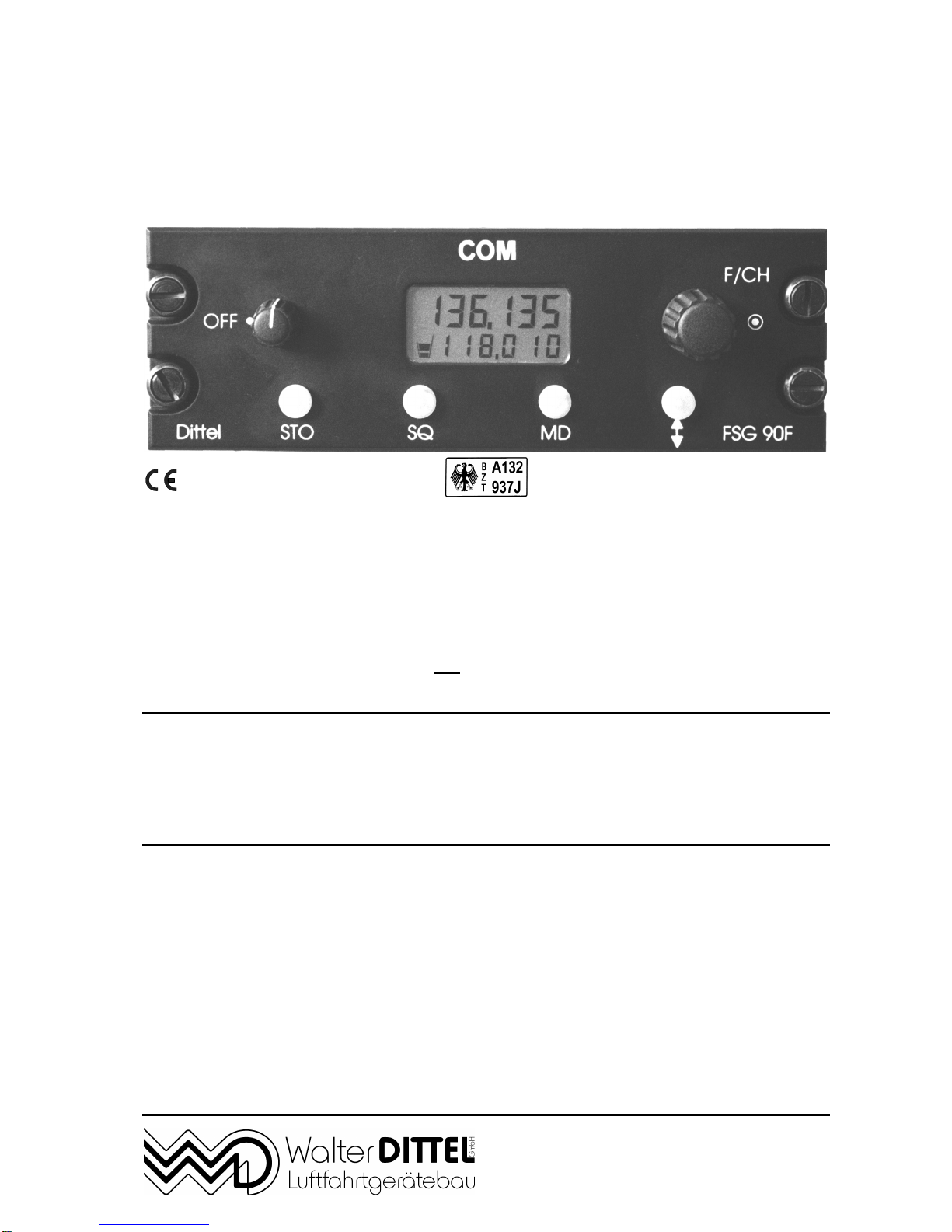
6 Watt FSG 90F
10 Watt FSG 90F-H1
No. LBA.O.10.911/98 JTSO
DFS-No.: B-7850/97
6 Watt – 10 Watt Dual Mode
VHF/AM AIRBAND TRANSCEIVERS
118.000 ... 136.975 MHz
8.33 kHz/25 kHz or ‘25 kHz only’ channel spacing
Installation & Operation
applies for FSG 90F article no. F10194
applies for FSG 90F-H1 article no. F10306
Before installing and operating the transceiver,
read this manual thoroughly, please!
Please observe the Safety Information!
Keep for further use!
Document No.: IM 034.00
Article-No.: D10033
Date of Issue November 2000
Avionics Division
Erpftinger Strasse 36 « D-86899 Landsberg « GERMANY
Telephone +49 8191/ 3351-0 « Fax +49 8191/ 3351-49
e-mail: firma@dittel.com « Internet: http://www.dittel.com

FSG 90F System
Airband Transceiver
Page 2 November 2000
W. Dittel GmbH
Warranty - Copyright - Service
Warranty
The details and data in this operator's manual correspond to the respective
state of technology on the day of printing. We reserve our right to change
without prior notice due to new technological design or corresponding new
production technology.
Walter Dittel GmbH takes no guarantee for these documents with respect to
application and interpretation.
Walter Dittel GmbH ("Warrantor") warrants to the purchaser of new radio
equipment of the warrantor's manufacture that such equipment shall be free
from defects in material and workmanship for a period of 24 month from the
date of delivery. Equipment and accessory items not manufactured by the
Warrantor carry the standard warranty (12 month) of the manufacturer
thereof.
This warranty does not cover equipment which has been
1. damaged or not maintained as reasonable and necessary,
2. modified in any way,
3. improperly installed,
4. repaired by someone other than the warrantor or an authorized
warranty avionics shop, or
5. used in a manner or purpose for which the equipment was not
intended.
This warranty shall not extend to incidental or consequential damages arising
from operation of the equipment or from any claimed breach of this warranty.
Copyright 1998 Walter Dittel GmbH
All rights reserved. This document contains proprietary information and such
information may not be disclosed to others for any purpose nor used for
manufacturing purposes without prior written permission of the manufacturer
Walter Dittel GmbH, Luftfahrtgeraetebau, D-86899 Landsberg am Lech,
Germany.
In this document no mention is made of patents, trademark rights, or other
proprietary rights which may attach to certain words or entries. The absence
of such mention, however, in no way implies that the words or entries in
question are exempt from such rights.
Service
The information in this Operator's Manual does not profess to include all the
details of design, production, or variation of the equipment, or to cover all the
possible contingencies which may arise during operation or maintenance.
Should any unusual problem arise or further information be desired, please
contact the Walter Dittel GmbH Service Department, Erpftinger Strasse 36,
D-86899 Landsberg am Lech, Germany.
Subject to technical changes Printed in Germany 14.09.01

FSG 90F System
Table of Content
November 2000 Page 3
W. Dittel GmbH
Table of Content
Page
Warranty - Copyright - Service..................................................................................... 2
Table of Content............................................................................................................ 3
List of Illustrations........................................................................................................ 5
Abbreviations................................................................................................................ 6
Section 1, Safety Information....................................................................................... 7
1.1 Used Symbols.................................................................................................... 8
Section 2, General Description.................................................................................... 9
2.1 Introduction ........................................................................................................ 9
2.2 Models of the FSG 90F System.......................................................................... 9
2.3 Application.......................................................................................................... 9
2.4 Brief Description............................................................................................... 10
2.5 System and Type Approval Information........................................................... 12
2.6 Operating License............................................................................................ 13
2.7 Equipment supplied.......................................................................................... 13
2.8 Optional Accessories ....................................................................................... 14
2.9 Accessories required, but not supplied ............................................................ 15
2.10 Microphone hints.............................................................................................. 15
Section 3, Installation................................................................................................. 17
3.1 General ............................................................................................................ 17
3.2 Unpacking and Inspecting Equipment .............................................................. 17
3.3 Pre-installation Test ......................................................................................... 17
3.3.1 Particular Remarks to FSG 90F(X) transmitter modulation .................................... 18
3.4 Mechanical Installation..................................................................................... 20
3.4.1 Transceiver installation......................................................................................... 20
3.4.2 Compass deviation ............................................................................................... 20
3.4.3 Antenna installation............................................................................................... 23
3.5 Airborne wiring................................................................................................. 24
3.5.1 General recommendations.................................................................................... 24
3.5.2 Microphone Connection........................................................................................ 28
3.5.3 Intercom (IC)......................................................................................................... 28
3.5.4 Loudspeaker / Headset interconnection ................................................................ 29
3.5.5 AF External Operation .......................................................................................... 29
3.5.6 Lighting the Frequency Display ............................................................................. 29
3.5.7 Connection to a 28 Vdc airborne system .............................................................. 30
3.6 Post-installation Check..................................................................................... 30
3.6.1 Testing on the Ground with Engine Off................................................................. 30
3.6.2 Ground checks with engine running...................................................................... 30

FSG 90F System
Table of Content
Page 4 November 2000
W. Dittel GmbH
Table of Content
Page
Section 4, Functional Description .............................................................................33
4.1 Introduction....................................................................................................... 33
4.2 Operator's Controls ..........................................................................................33
4.3 Frequency Display, 5-digit or 6-digit Liquid Crystal Display (LCD). ..................36
4.4 Connectors at rear side....................................................................................37
Section 5, Set-up Procedure ...................................................................................... 39
5.1 Calling SET-UP without password.................................................................... 40
5.2 Calling SET-UP with password......................................................................... 40
5.3 Interrupt the SET-UP procedure....................................................................... 41
5.4 SET-UP procedure...........................................................................................41
5.4.1 Adjusting the automatic squelch threshold ............................................................41
5.4.2 Adjusting the microphone sensitivity (Dynamic or amplified/carbon microphones) 41
5.4.3 Adjusting the Intercom volume..............................................................................42
5.4.4 Adjusting the Sidetone volume..............................................................................43
5.4.5 Adjusting the headset volume ...............................................................................43
5.4.6 Selecting '25 kHz only' or combined 8.33/25 kHz channel spacing........................44
5.4.7 Deleting occupied channel memories....................................................................44
5.4.8 Selecting AF EXTERNAL (ON/OFF) .....................................................................45
5.4.9 Selecting 'CHANNEL MODE ONLY' or 'NO RESTRICTION'.................................45
5.4.10 Selecting 'Transmitter Blocking' during receive (ON/OFF).....................................45
5.4.11 Service (ON/OFF) .................................................................................................46
5.4.12 Optional module (ON/OFF) ...................................................................................46
5.4.13 Entering a password..............................................................................................46
5.4.14 Reset.....................................................................................................................47
Section 6, Operating Instruction................................................................................ 49
6.1 Introduction....................................................................................................... 49
6.2 Turning ON - Selecting Frequency/Channel Name - Volume...........................49
6.3 Receive (Listen) Operation ............................................................................... 50
6.4 Transmit (Talk) Operation ................................................................................51
6.5 Storing a new Frequency/Channel Name......................................................... 52
6.6 Recall of stored Frequency/Channel Name...................................................... 52
6.7 Squelch (SQ) Operation...................................................................................52
6.8 Intercom ...........................................................................................................53
6.9 AF External....................................................................................................... 53
6.10 Lighting.............................................................................................................53
6.11 Turning OFF.....................................................................................................53
6.12 Checking the A/C onboard supply.................................................................... 54
6.13 Operating times with radio supplied from 12 V battery only............................. 55
6.14 Emergency Operation ......................................................................................55

FSG 90F System
Table of Content
November 2000 Page 5
W. Dittel GmbH
Table of Content
Page
Appendix A, Technical Summary .............................................................................. 57
A1 General ............................................................................................................ 57
A2 Dimensions, Weight, Fuses ............................................................................. 58
A3 Approvals......................................................................................................... 58
A4 Receiver Characteristics .................................................................................. 59
A5 Transmitter Characteristics .............................................................................. 61
Appendix B, Environmental Performance Classification........................................ 62
Appendix C, ICAO Frequency-Channel pairing plan for combined
8.33 kHz /25 kHz Operation................................................................. 63
Appendix D, Certificates............................................................................................. 64
List of Illustrations
Fig. Page
3-1 Test Setup, Envelope Detector ................................................................................... 19
3-2 Deviation of a compass by an operating FSG 90F(X), dependent on
the distance between compass center and contour of transceiver.............................. 20
3-3 FSG 90F(X), Dimensions, Installation Drawing............................................................ 21
3-4 FSG 90F(X), Installation of the Fastener Strips ........................................................... 22
3-5 Hook-up Diagram using wire harness F10189, 1-2 dynamic microphone(s)............... 25
3-6 Hook-up Diagram using wire harness F10190,
1-2 dynamic microphone(s) and Intercom .................................................................. 26
3-7 Hook-up Diagram, 2 amplified/carbon microphones and Intercom ............................. 27
4-1 Operator's Controls and Indicators............................................................................. 33

FSG 90F System
Abbreviations
Page 6 November 2000
W. Dittel GmbH
Abbreviations
A/C Aircraft
A/N Article Number (DITTEL)
AGC Automatic Gain Control
Ah Ampere hour
AM Amplitude Modulation
ANT Antenna
Ass'y Assembly
AWG American Wire Gauge
ccw
Counterclockwise (turn left ?)
CH Channel
CTS Ready-to-Transmit
cw
Clockwise (turn right ?)
dB Decibel
dia. Diameter
EMF Electromotive Force (voltage of
an open circuit)
F/CH Frequency/Channel
FL Flight Level
g Acceleration due to gravity
GND Ground
HI High Power
Hz Hertz
ICAO
International Civil Aviation Organization
IF Intermediate Frequency
kHz Kilohertz
LCD Liquid Crystal Display
LED Light Emitting Diode
LO Low Power
LOS Line-Of-Sight
m Modulation
mA Milliamperes
MD Mode
MHz Megahertz
MIC Microphone
mW Milliwatt
NM Nautical miles
nW Nanowatt (10-9)
PEP Peak Envelope Power
PLL Phase-Locked Loop
ppm parts per million
PTT Push-To-Talk
pW Picowatt (10
-12
)
PWR Power
RF Radio Frequency
rms Effective value (root mean
square)
RTS Invitation to send
RX Receive
RxD Receive data
S+N/N Signal-to-Noise Ratio
SINAD
Ratio:
Signal noise distortion
noise distortion
+ +
+
SPKR Loudspeaker
SQ Squelch
STBY Standby
STO Store
SWR Standing-Wave Ratio
TOT Time out timer
TX Transmit
TxD Transmit data
VCO Voltage-Controlled Oscillator
Vdc Volts, direct current
VHF Very-High Frequency
VOL Volume
VSWR Voltage Standing-Wave Ratio
W Watt
O Ohm
°C Degrees Centigrade
°F Degrees Fahrenheit

FSG 90F System
1. Safety Information
November 2000 Page 7
W. Dittel GmbH
Section 1 Safety Information
Every radio, when transmitting, radiates energy into the atmosphere that may, under
certain conditions, cause the generation of sparks. All users of our radios should be
aware of the following warning:
Do not operate this radio in an explosive atmosphere (petroleum fuels,
solvents, dust, etc.)!
During normal use, the radio will subject you to radio frequency energy substantially
below the level where any kind of harm is reported.
TO ENSURE PERSONAL SAFETY, please observe the following simple rules:
• DO NOT transmit when the antenna is very close to, or touching, exposed parts of the
body, especially the face and eyes.
• DO NOT transmit on a busy channel.
• DO NOT press the transmit (PTT) key when not actually desiring to transmit.
• DO NOT transmit in closed aircraft or vehicles with the antenna (or part of it) inside the
cabin. This may cause malfunction of the avionics or trigger the airbag! Always operate
the radio FSG 90F(X) with a suitable outside / external antenna! Assure appropriate
lightning protection where elevated outdoor antennas are used.
• DO NOT operate the radio whilst driving. It should also be noticed that the use of a
hand held microphone while driving could constitute an offence under the Road Traffic
Regulations in certain countries.
• DO NOT allow children to play with any radio equipment containing a transmitter.
• DO NOT call radio’s SET-UP in flight or whilst driving a vehicle. Transmit and receive
are partially disabled!
• After each SET-UP check all settings of the radio and cockpit instruments for correct
function before the next flight or application!
• Always switch OFF the radio first when installing the unit into vehicles or aircraft when
removing from it!
• Always switch OFF the radio first when starting an engine or vehicle!
• When operating the FSG 90F(X) on a 24 Vdc source a suitable Voltage Converter
24 Vdc/12 Vdc of at least 4 Amps must be used!
• The FSG 90F(X) may be used exclusively for communication on the airband
frequencies.
• Unauthorized modifications and changes of the system are forbidden.
• When replacing defective parts use only original spare parts or standard parts
recommended by the manufacturer!
• In aircraft or vehicles a suitable noise canceling microphone or headset for aircraft
radios shall be used.
• A backup microphone should always be carried during any flight. Even new
microphones can fail.
• Volume is very important. Increasing speaking levels while the lips are facing the
microphone, but not straining or pushing to yelling levels will increase clarity.
FSG 90F System
1. Safety Information
Page 8 November 2000
W. Dittel GmbH
• Prior to any flight verify proper FSG 90F(X) functions by means of a short
communications test. It has to be taken into account that with a faulty antenna or
cable this COM test may absolutely turn out positive at the airfield or in short distance
to the ground station. But at distances of 2 to 6 miles a faulty antenna and/or cable
will cause communication breakdown!
• Push-to-Talk keys may stick occasionally. Therefore, observe while transmitting the
transmit (TX) symbol at the FSG 90F(X) display. This TX symbol must disappear
when releasing the PTT key. After 2 minutes continuous TX the built-in transmit time
out timer disables the transmitter in order to avoid continuous channel blocking.
Then, the whole display warns by continuous flashing. Refer to appropriate hints in
this manual.
• Replace blown fuse only against correct type with specified nominal value.
Investigate the cause.
1.1 Used Symbols
In this manual the following symbols are used:
DANGER!
describes an immediate threatening danger! Failing to observe the note
may cause death or heavy injuries!
CAUTION!
describes a special note for operation. Failing to observe the note may
cause damage of the transceiver and/or stored data may be deleted (SETUP or user programmed memory)!
IMPORTANT!
describes explanations and other useful hints. Failing to observe the note
may cause degraded performance and/or unsatisfying operation!

FSG 90F System
2. General Description
November 2000 Page 9
W. Dittel GmbH
Section 2 General Description
2.1 Introduction
This installation and operating manual IM 034.00 contains instructions and descriptions
for application, installation, presetting operation and testing, as well as interconnecting
diagrams of the multi-use FSG 90F / FSG 90F-H1 VHF/AM Transceiver System of Walter
Dittel GmbH, Luftfahrtgeraetebau, D-86899 Landsberg, Germany.
The maintenance manual MRM 034.00 contains detailed circuit description, repair
instructions, alignment procedures, testing instructions, and an illustrated parts list.
2.2 Models of the FSG 90F System
This manual refers to 2 out of 8 models available up to now.
F10194, VHF/AM Dual Mode Airband Transceiver FSG 90F
Frequency range: 118.000 to 136.975 MHz, channel spacing 8.33 kHz/25 kHz, results in
2,278 channels, or 118.000 to 136.975 MHz, channel spacing 25 kHz, results in 760
channels. 99 channel memories for combined 8.33/25 kHz mode, additional 99 memory
channels for '25 kHz only' mode, 6 Watt RF output power, 10 - 16.5 Vdc supply. The
radio fits a standard ARINC NORM rectangular opening.
IDENT.: MODEL 90F-25/8.33 (ED-23B CLASS C / CLASS E RECEIVER, CLASS 4 / CLASS 6
TRANSMITTER).
F10306, VHF/AM Dual Mode Mode Airband Transceiver FSG 90F-H1
Frequency range: 118.000 to 136.975 MHz, channel spacing 8.33 kHz/25 kHz, results in
2,278 channels, or 118.000 to 136.975 MHz, channel spacing 25 kHz, results in 760
channels. 99 channel memories for combined 8.33/25 kHz mode, additional 99 memory
channels for '25 kHz only' mode, 10 Watt RF output power, 10 - 16.5 Vdc supply. The
radio fits a standard ARINC NORM rectangular opening.
IDENT.: MODEL 90F-H1-25/8.33 (ED-23B CLASS C / CLASS E RECEIVER, CLASS 4 / CLASS 6
TRANSMITTER).
2.3 Application
The equipment is well suited for operation in powered aircraft and helicopter with
reciprocating turboprop and turbojet engine.
Ultra low power consumption in conjunction with extremely wide DC supply voltage
range, small dimensions and wide scope of accessories allow universal FSG 90F(X)
airborne applications in any powered aircraft, motor glider and Ultralight, and in glider
and balloon, for primary or (also battery supplied) backup operation.
 Loading...