

Walter Dittel FSG 70, FSG 71M Installation & Operation Manual
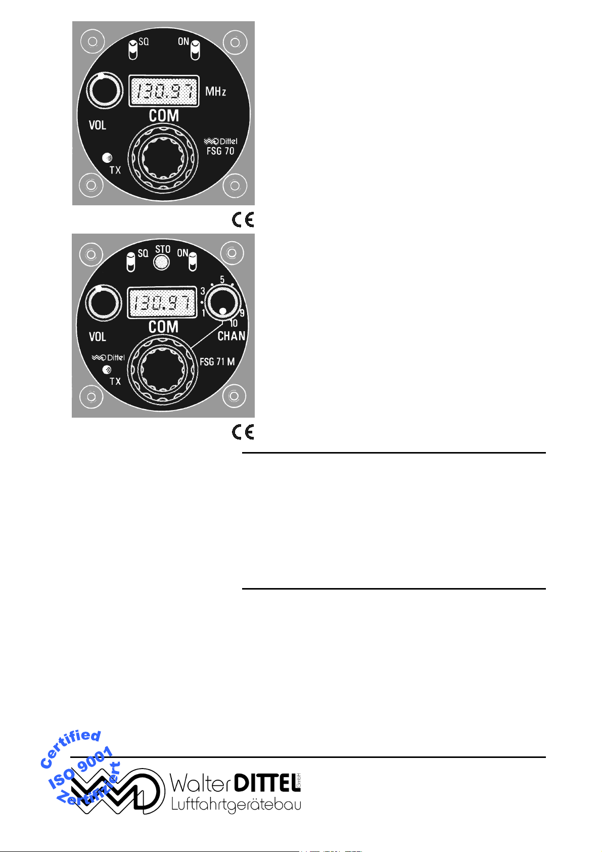
FSG 70
VHF/AM COM
TRANSCEIVER
118.000 … 136.975 MHz
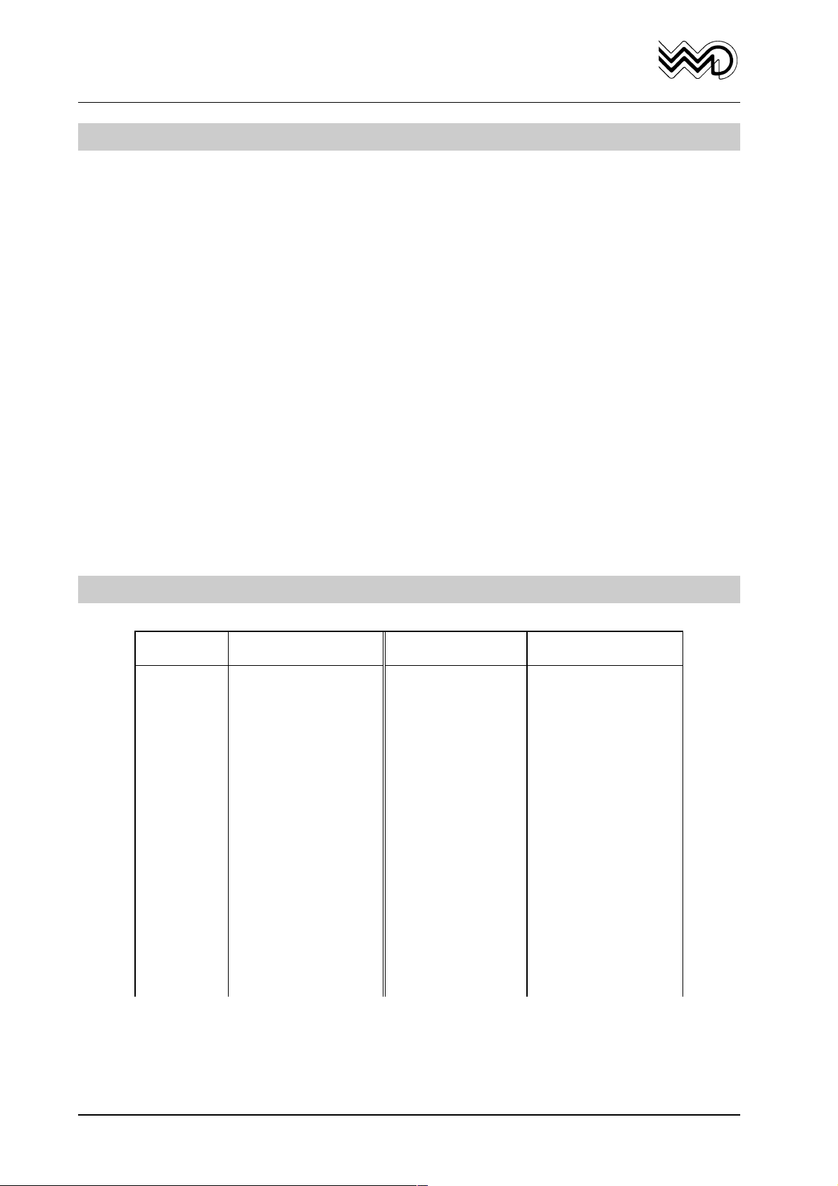
FSG 71M
VHF/AM COM
TRANSCEIVER
118.000 … 136.975 MHz
Installation & Operation
Manual
applies for FSG 70, article no. F10002
applies for FSG 71M, article no. F10003
Before installing and operating the radio,
read this manual thoroughly, please!
Please observe the Safety Information!
Keep for further use!
Document No. 027.HB.00E
Revision No. (Reprint) 1
Date/Issue July 1998
Avionics Division
Erpftinger Strasse 36 « D-86899 Landsberg « Germany
Telephone +49 8191/3351-0 « Fax +49 8191/3351-49
e-mail: firma@dittel.com « Internet: http://www.dittel.com

FSG 70/FSG 71M
OPERATION MANUAL
Warranty - Copyright - Service
Warranty
The details and data in this operator's manual correspond to the respective state of
technology on the day of printing. We reserve our right to change without prior notice
due to new technological design or corresponding new production technology.
WALTER DITTEL GmbH takes no guarantee for these documents with respect to
application and interpretation.
WALTER DITTEL GmbH ("Warrantor") warrants to the purchaser of new radio equipment
of the warrantor's manufacture that such equipment shall be free from defects in
material and workmanship for a period of 24 month from the date of delivery.
Equipment and accessory items not manufactured by the Warrantor carry the standard
warranty (12 month) of the manufacturer thereof.
This warranty does not cover equipment which has been
1. damaged or not maintained as reasonable and necessary,
2. modified in any way,
3. improperly installed,
4. repaired by someone other than the warrantor or an authorized
warranty repair station, or
5. used in a manner or purpose for which the equipment was not
intended.
This warranty shall not extend to incidental or consequential damages arising from
operation of the equipment or from any claimed breach of this warranty.
W. Dittel GmbH
Copyright 1990 Walter Dittel GmbH, reprint July 1998
All rights reserved. This document contains proprietary information and such
information may not be disclosed to others for any purpose nor used for manufacturing
purposes without prior written permission of the manufacturer Walter Dittel GmbH,
Luftfahrtgeraetebau, D-86899 Landsberg am Lech, Germany.
In this document no mention is made of patents, trademark rights, or other proprietary
rights which may attach to certain words or entries. The absence of such mention,
however, in no way implies that the words or entries in question are exempt from such
rights.
Service
The information in this Operator's Manual does not profess to include all the details of
design, production, or variation of the equipment, or to cover all the possible
contingencies which may arise during operation or maintenance.
Should any unusual problem arise or further information be desired, please contact the
Walter Dittel GmbH Service Department, Erpftinger Strasse 36, D-86899 Landsberg
am Lech, Germany.
Since May 1994 the company
ANTON LANG FLUGFUNK-SERVICE
Pappelweg 26
D-86972 Schwabniederhofen
Germany
Tel: +49-8861 / 1739
Fax: +49-8861 / 1590
took over all repair work of airband radios of Walter Dittel GmbH, Luftfahrtgeraetebau,
Erpftinger Stasse 36, D-86899 Landsberg am Lech, Germany.
The offered services of company LANG include all repairs, overhaul, maintenance and
inspection according to the regulations of the German Federal Aviation Authority
(Luftfahrtbundesamt, LBA). The company LANG is an authorized repair station,
certified by the LBA under registration number II-A272.
IMPORTANT: Also all warranty repairs are done solely by company LANG.
Subject to technical changes Printed in Germany 03.05.01
Page ii Reprint July 1998

FSG 70/FSG 71M
W. Dittel GmbH
OPERATION MANUAL
Table of contents
Paragraph Page
Warranty - Copyright - Service ................................................................................................... ii
Table of contents....................................................................................................................... iii
List of illustrations ...................................................................................................................... iv
List of valid pages...................................................................................................................... iv
Section I, Safety Information .................................................................................... 1-1
1.1 Used Symbols..............................................................................................................1-2
Section II, General Information................................................................................. 2-1
2.1 Introduction..................................................................................................................2-1
2.2 Application ...................................................................................................................2-1
2.3 Brief Description...........................................................................................................2-2
2.4 FSG 70-System Technical Data...................................................................................2-3
2.4.1 General Data ........................................................................................................................ 2-3
2.4.2 Receiver Electrical Data .......................................................................................................2-4
2.4.3 Transmitter Electrical Data ................................................................................................... 2-5
2.4.4 Additional features................................................................................................................ 2-5
2.5 Units and Accessories supplied ...................................................................................2-6
2.6 Accessories required, but not supplied.........................................................................2-6
2.7 Summary of the FSG 70-System .................................................................................2-7
Section III, Installation............................................................................................... 3-1
3.1 General........................................................................................................................3-1
3.2 Pre-installation Check ..................................................................................................3-1
3.2.1 Matching the Microphones ...................................................................................................3-2
3.2.2 Audio Sidetone .....................................................................................................................3-2
3.3 Mechanical Installation.................................................................................................3-4
3.3.1 Installation of the Transceiver ..............................................................................................3-4
3.3.2 Influence on Compass ......................................................................................................... 3-4
3.3.3 Antenna Installation.................................................................................................................. 3-7
3.4 On-board Wiring ..........................................................................................................3-8
3.4.1 General Instructions for On-Board Wiring ............................................................................ 3-8
3.4.2 Connection of the microphones ......................................................................................... 3-12
3.4.3 Intercommunication (IC) ..................................................................................................... 3-12
3.4.4 Speaker/Phone connection ................................................................................................ 3-12
3.4.5 AF-External Input ...............................................................................................................3-12
3.4.6 Illumination of the Frequency Display.................................................................................3-13
3.4.7 Connection to 28Vdc aircraft bus ....................................................................................... 3-13
3.5 Post Installation Check...............................................................................................3-14
3.5.1 Testing on the Ground with the Engine Off ........................................................................ 3-14
3.5.2 Testing on the Ground with Engine Running...................................................................... 3-14
Section IV, Operation ................................................................................................ 4-1
4.1 Control Functions.........................................................................................................4-1
4.2 Operating Instructions..................................................................................................4-2
4.3 Programming the Channel Frequency Memory (FSG 71M only)..................................4-3
4.4 Recall of Stored Frequencies.......................................................................................4-3
4.5 Battery Check ..............................................................................................................4-3
4.6 Emergency Operation ..................................................................................................4-4
4.7 Squelch Function (SQ).................................................................................................4-4
4.8 Intercommunication (IC)...............................................................................................4-4
4.9 Audio External..............................................................................................................4-4
Appendix A, Certificate..............................................................................................A-1
Reprint July 1998 Page iii
FSG 70/FSG 71M
OPERATION MANUAL
W. Dittel GmbH
List of illustrations
Figure Page
3-1 Location of Audio Sidetone Control and Microphone Gain Control ............................................... 3-2
3-2 Test Set-up, Envelope Detector .................................................................................................... 3-3
3-3 Deviation of Compass by FSG 70/FSG 71M depending on the Distance between Center of
Compass and Contour of Transceiver ..........................................................................................3-4
3-4 FSG 70, Dimensions, Installation Drawing.................................................................................... 3-5
3-5 FSG 71M, Dimensions, Installation Drawing................................................................................. 3-6
3-6 Connector Assembling, Sliding Lock Assembly ............................................................................3-8
3-7 FSG 70/FSG 71M, Hook-up Diagram without INTERCOM, 1-2 Dynamic Microphones............... 3-9
3-8 FSG 70/FSG 71M, Hook-up Diagram using wire harness F10029,
1-2 Dynamic Microphones and INTERCOM ...............................................................................3-10
3-9 FSG 70/FSG 71M, Hook-up Diagram, 1-2 Standard Carbon Microphone/s
and INTERCOM .......................................................................................................................... 3-11
3-10 Activating the AF EXTERNAL Input ............................................................................................3-13
4-1 Controls and Readouts.................................................................................................................. 4-1
List of valid pages
Page Effective Date Page Effective Date
Title page
ii
iii
iv
1 - 1
1 - 2
2 - 1
2 - 2
2 - 3
2 - 4
2 - 5
2 - 6
2 - 7
2 - 8
3 - 1
3 - 2
3 - 3
July 1998
July 1998
July 1998
July 1998
July 1998
July 1998
July 1998
July 1998
July 1998
July 1998
July 1998
July 1998
July 1998
July 1998
July 1998
July 1998
July 1998
3 - 4
3 - 5
3 - 6
3 - 7
3 - 8
3 - 9
3 - 10
3 - 11
3 - 12
3 - 13
3 - 14
4 - 1
4 - 2
4 - 3
4 - 4
A - 1
July 1998
July 1998
July 1998
July 1998
July 1998
July 1998
July 1998
July 1998
July 1998
July 1998
July 1998
July 1998
July 1998
July 1998
July 1998
July 1998
Page iv Reprint July 1998

FSG 70/FSG 71M
W. Dittel GmbH
Section I Safety Information
Every radio, when transmitting, radiates energy into the atmosphere that may, under
certain conditions, cause the generation of sparks. All users of our radios should be
aware of the following warning:
Do not operate this radio in an explosive atmosphere (petroleum fuels,
solvents, dust, etc.)!
During normal use, the radio will subject you to radio frequency energy substantially
below the level where any kind of harm is reported.
TO ENSURE PERSONAL SAFETY, please observe the following simple rules:
• DO NOT transmit when the antenna is very close to, or touching, exposed parts of the
body, especially the face and eyes.
• DO NOT transmit on a busy channel.
• DO NOT press the transmit (PTT) key when not actually desiring to transmit.
• DO NOT transmit in closed aircraft or vehicles with the antenna inside the cabin. This
may cause malfunction of the avionics or trigger the airbag! Always operate the radio
FSG 70/71M with a suitable outside / external antenna! Assure appropriate lightning
protection where elevated outdoor antennas are used.
• DO NOT operate the radio whilst driving. It should also be noticed that the use of a
hand held microphone while driving could constitute an offence under the Road Traffic
Regulations in certain countries.
• DO NOT allow children to play with any radio equipment containing a transmitter.
• Always switch OFF the radio first when installing the unit into vehicles, aircraft or
carrier cases or when removing from it!
• Always switch OFF the radio first when starting an engine or vehicle!
• When operating the FSG 70/71M on a 24/28Vdc source a suitable Voltage Converter
24Vdc/12Vdc of at least 4 Amps must be used!
• The FSG 70/71M may be used exclusively for communication on the airband
frequencies.
• Unauthorized modifications and changes of the system are forbidden.
• When replacing defective parts use only original spare parts or standard parts
recommended by the manufacturer!
• In aircraft or vehicles a suitable noise canceling microphone or headset for aircraft
radios shall be used.
• A backup microphone should always be carried during any flight. Even new
microphones can fail.
• Volume is very important. Increasing speaking levels while the lips are facing the
microphone, but not straining or pushing to yelling levels will increase clarity.
• Prior to any flight verify proper FSG 70/71M functions by means of a short
communications test. It has to be taken into account that with a faulty antenna or cable
this COM test may absolutely turn out positive at the airfield or in short distance to the
ground station. But at a distance of 2 to 6 miles faulty antenna and/or cables will cause
communication breakdown!
• Push-to-Talk keys may stick occasionally. Therefore, observe while transmitting the
yellow TX LED at the FSG 70/71M. This TX LED must go off when releasing the PTT
key.
• Replace blown fuse only against correct type with specified nominal value. Investigate
the cause.
OPERATION MANUAL
Reprint July 1998 Page 1 - 1
FSG 70/FSG 71M
OPERATION MANUAL
1.1 Used Symbols
In this manual the following symbols are used:
DANGER!
describes an immediate threatening danger! Failing to observe the note
may cause death or heavy injuries!
CAUTION!
describes a special note for operation. Failing to observe the note may
cause damage of the transceiver and/or stored data may be deleted (user
programmed memory)!
IMPORTANT!
describes explanations and other useful hints. Failing to observe the note
may cause degraded performance and/or unsatisfying operation!
W. Dittel GmbH
Page 1 - 2 Reprint July 1998

W. Dittel GmbH
Section II General Information
2.1 Introduction
This installation and operation manual, 027.HB.00E, contains instructions and
descriptions for application, installation and operation of the FSG 70 and FSG 71M 760channel VHF aircraft transceivers of WALTER DITTEL GmbH's FSG 70-SYSTEM.
The Service Manual 027.HB.10 contains detailed circuit description, repair instructions,
alignment procedure, testing instructions, and a detailed Illustrated Parts List.
2.2 Application
The transceivers of the FSG 70-System are fully transistorized VHF radios of
monoblock construction for two way voice communications within the extended
frequency range of 118.00 MHz to 136.975 MHz in 25 kHz increments (760 channels).
The equipment is well suited for reciprocating, turbopropeller or turbojet engine aircraft
as well as for helicopters with reciprocating or turbojet engines. The equipment comply
with applicable RTCA Performance Standards (observe national regulations).
Featuring small dimensions, low weight and extremely low current consumption, these
units are suitable in motorized gliders, gliders, balloons, Ultralights, homebuilts,
experimentals and as emergency back-up transceiver too.
Together with the W. Dittel GmbH carrying cases the transceivers of the FSG 70-
SYSTEM can be used as portable, mobile and fixed base ground stations. The excellent
suitability of the units to be powered by batteries should be emphasized. Special
modes like Intercom, AF-External Input, storage of VHF-frequencies etc. are possible
without any other additional equipment (depending on type of unit).
The LC-frequency display can be illuminated.
The transceivers comply with the Performance Standards of RTCA- and EUROCAE-
regulations. Additionally they comply with the regulations for groundstations.
FSG 70/FSG 71M
OPERATION MANUAL
Reprint July 1998 Page 2 - 1

FSG 70/FSG 71M
OPERATION MANUAL
2.3 Brief Description
The FSG 70 and FSG 71M are miniaturized lightweight panel mounted transceivers
designed to operate in the VHF-COM frequency range from 118.000 to 136.975 MHz
in 25 kHz increments, thus providing 760 channels over a standard communication
distance of 100 nautical miles at FL 70.
The case dimensions fit into a standard 2¼" cut-out of the instrument panel. Only four
screws (M 4 x 16) are used to install the transceiver units. Electrical connections to the
environment are made through a 15-pole SUB-D connector and a BNC female
connector at the rear panel of the units.
The operational frequency is displayed by means of a Liquid Crystal Display with five
digits following the ICAO-scheme:
The least significant digit is omitted (e.g. 127.875 is displayed as 127.87 MHz).
The transceivers consist of five main sections: Digital frequency synthesizer, receiver,
transmitter (6 watts carrier, 24 watts PEP), audio circuits, and LCD frequency display
circuitry.
Model FSG 71M includes an additional section:
A non volatile electronic ten channel memory. This memory and its command controls
make the only difference between FSG 70 and FSG 71M. The operational frequency of
the FSG 71M unit is indicated by the LCD and may be selected in two modes on the
front panel:
a) Direct mode: The channel control knob on the right front side must be set to full
ccw position. By using the MHz/kHz coaxial double knob on the front panel all 760
channels may be selected as usual.
b) Storage mode: The channel control knob is set to select the desired channel for
any "Read" or "Store" action. Up to 10 out of 760 channels may be programmed
and permanently stored for up to five to six years in the electronic memory. Storage
channels may also be reprogrammed if necessary, even in flight.
The FSG 70 has no channel control. Frequency selection can be performed only in
direct mode using the coaxial double knob.
Further features incorporate an automatic squelch circuit with manual override and
automatic adaptation to pulsed noise, separate microphone inputs for low level
dynamic and standard carbon mikes, compressor for modulation level control, a
"transmitter ON" annunciator LED, an intercom mode ,a wide supply voltage range of
9.7 to 15.2Vdc, audio lowpass filter for CLIMAX environment, additional AF input for
application of external (e.g. NAV-) audio, internal lighting of the frequency display and
a very comprehensive indication of "Low Supply" by flashing of the frequency display.
Audio output is delivered separately for speakers (receive only) and for headphones
(receive and transmit sidetone).
The transceivers can be supplied either direct from 12/14Vdc-buses or via a voltage
converter (Type S20000) from 28Vdc-buses.
An automatic power-saving circuit prevents unnecessary power consumption in some
operating modes, thereby extending the operating time available from one battery
charge. Particularly the no-signal current drain in the squelch (SQ) mode is reduced to
the very low level of approx. 25 mA.
W. Dittel GmbH
Page 2 - 2 Reprint July 1998

W. Dittel GmbH
2.4 FSG 70-System Technical Data
2.4.1 General Data
FSG 70/FSG 71M
OPERATION MANUAL
Model:
Operating voltage: 13.8Vdc +10% / -20%
Emergency operation: 9.7Vdc to 11Vdc
Power consumption: Stand by: 27mA (typical)
Recommended fuse: 2.5 Amp semi time lag acting
Temperature range: -20°C to +55°C, short-term +71°C
Storage Temperature: -55°C to +85°C
Altitude capability: 15,000m/50,000ft. MSL
Vibration stability: 0.1", 5 - 27Hz / 1.5g, 27 - 500Hz /
Front panel dimensions:
Installation depth
(measured from rear of panel): 191mm + approx. 50mm for plug and wires
Overall dimensions: W = 63mm, H = 61mm, D = 237mm
Weight:
FSG 70/FSG 71M
Intercom: 85mA (typical)
Receive (voice): 140mA (typical)
Transmit (voice): 1.5A (typical)
Illumination: 20mA additional
1g, up to 2000Hz
∅ 57.2mm corresponds to 2¼" cut-out
FSG 70: 0.74kg/1.6lb
FSG 71M: 0.80kg/1.76lb
Equipment category according to
RTCA DO-156:
RTCA DO-157:
Performance category according to
DO-160 A: D1/A/MNO/XXXXXXZBABZ
The radios FSG 70 and FSG 71M fulfil the technical requirements of ICAO
Annex 10, immunity against FM Broadcast Interference.
Class C
Class 4
Reprint July 1998 Page 2 - 3

FSG 70/FSG 71M
OPERATION MANUAL
2.4.2 Receiver Electrical Data
Receiver type: Single superheterodyne
Frequency range: 118.000MHz to 136.975MHz
Number of channels (FSG 70):
W. Dittel GmbH
760
Number of channels (FSG 71M):
760, of which 10 frequencies may be free
programmed and permanently stored
Channel spacing: 25kHz
Sensitivity:
≤1.0µV for 6dB (S+N)/N, 50 Ohms, mod.
1000Hz/m = 30 %
Bandwidth:
Selectivity:
> ± 8kHz at 6dB
≥ 70dB at ± 25kHz;
≥ 40dB at ± 17kHz
Squelch: Automatic, defeatable, threshold internally
adjustable ca. 0.5 - 3µV
Gain control:
Spurious response:
Spurious radiation:
Distortion, m = 85%:
Frequency response:
≤ 6dB (5µV to 200mV)
≥ 80dB (image); ≥ 75dB (others)
< 5 × 10
-11
Watt
≤ 10%
≤ 6dB, 350 to 2,500Hz
≥ 18dB at 4,000Hz
Intermediate frequency: 10.0MHz
Rated output: Headphone 35mW into 500Ω, adjustable
Loudspeaker 8W into 2Ω
4W into 4Ω
Page 2 - 4 Reprint July 1998
 Loading...