

Page 1
User's Guide
60-C 780
Page 2

TABLE OF CONTENTS
Page
I - Introduction
...........................................................................................................................................................
3
II -
Safety instructions
...............................................................................................................................................
4,5
III - Equipment controls
............................................................................................................................................
6
A) Control panel pictograms
..........................................................................................................................
6
B) Front and back view of the machine
.........................................................................................................
7
C) Wand control buttons
.................................................................................................................................
8
IV - Control
panel
......................................................................................................................................................
9
A) Main power switch
....................................................................................................................................
9
B) Solution pump switch
................................................................................................................................
9
C)
Indicator light
............................................................................................................................................
9
D) Accessory outlet
........................................................................................................................................
9
V - Start-up pro
cedure
...............................................................................................................................................
A) What is included in the box
......................................................................................................................
B) Filling the reservoir
...................................................................................................................................
C) Mounting a cleaning pad
...........................................................................................................................
D) Plugging in the power cord
.......................................................................................................................
E)
Plugging in the ground clamp
...................................................................................................................
VI - Using the hand wan
d to clean and passivate
.....................................................................................................
A
)
S
electing the proper pumpin
g mode
.........................................................................................................
B)
Cleaning and passivating
...........................................................................................................................
C) Neutralizing
...............................................................................................................................................
VII - Using the Mini Wan
d (optional) to clean and passivate
..................................................................................
A) Manual pumping mode
.............................................................................................................................
B) Cleaning and passivating
...........................................................................................................................
C) Neutralizing
...............................................................................................................................................
D) List of supplies and part numbers
.............................................................................................................
3
VIII - Using the Marking Wand (optional)
................................................................................................................
A) Procedure for marking
...............................................................................................................................
B) Marking Wand supplies and part numbers
................................................................................................
IX - Neutralizing
........................................................................................................................................................
Page 3

Page
X - Accessories
. . . . . . . . . . . . . . . . . . . . . . . . . . . . . . . . . . . . . . . . . . . . . . . . . . . . . . . . . . . . . . . . . . . . . . . . . . . . .
A) Cleaning tips
. . . . . . . . . . . . . . . . . . . . . . . . . . . . . . . . . . . . . . . . . . . . . . . . . . . . . . . . . . . . . . . . . . . . . . .
B) Cleaning pads
. . . . . . . . . . . . . . . . . . . . . . . . . . . . . . . . . . . . . . . . . . . . . . . . . . . . . . . . . . . . . . . . . . . . . .
C) Cleaning boots
D) PTFE clamp rings
. . . . . . . . . . . . . . . . . . . . . . . . . . . . . . . . . . . . . . . . . . . . . . . . . . . . . . . . . . . . . . . . . . .
20
E) Surfox-T solution
20
XI - Safety features
. . . . . . . . . . . . . . . . . . . . . . . . . . . . . . . . . . . . . . . . . . . . . . . . . . . . . . . . . . . . . . . . . . . . . . . . . .
21
A) Sparks
on the tip/work piece
21
B) Interna
l temperature
21
C) Welds that cannot be cleaned
. . . . . . . . . . . . . . . . . . . . . . . . . . . . . . . . . . . . . . . . . . . . . . . . . . . . . . . . . .
21
XII - Technical data
22
XIII - Wa
rranty and service
23
A) War
ranty policy
23
B) Where to get service
. . . . . . . . . . . . . . . . . . . . . . . . . . . . . . . . . . . . . . . . . . . . . . . . . . . . . . . . . . . . . . . . .
23
2
Page 4

INTRODUCTION
Congratulations on purchasing the finest electrochemical weld cleaning and passivation equipment available today.
WALTER's SURFOX
weld cleaning equipment quickly, easily and cost effectively removes the heat tint created
during TIG welding while completely passivating the stainless steel surface.
Be
fore starting
owner's manual completely as we take you step-by-step through the
intenance procedures of your new SURFOX
TM
equipment. Your new SURFOX
TM
machine
has been built with extra d
urability to stand up to the hea
vy demands of industrial use. However, like any piece of
electrical equipment, care and safety shou
ld always be taken when using and ma
intaining this valuable investment.
With proper care and maintenance your SURFOX
TM
equipment will provide years of dependable service.
To learn more about the other Walter products
In Canada:
www.jwalter.ca
www.jwalter.ca
In USA:
www.jwalterinc.com
www.jwalterinc.com
In Mexico:
mex.walter.com
OPERATION
The Surfox machine works by an electrochemical process to clean and passivate the welds on stainless steel.
clean the welds. The process takes only a few seconds without damaging or scratching the surface of your part.
YOUR SURFOX
TM
MACHINE CAN CLEAN:
o TIG welds
o Plasma welds
o Laser welds
o Spot welds
o MIG welds (with Pulse technology)
BASICS OF PASSIVATION:
o Cleaning of the welds not only for aesthetic purposes but most importantly for passivation.
o Passivation is the treatment of stainless steel surfaces to remove contaminants and promote the
formation of the passive film layer.
o This passive film layer will assure the corrosion resistance of stainless steel.
o If passivation is not done properly, the stainless steel
and heat affected areas
may
start to rust.
3
I - INTRODUCTION
Page 5

II - SAFETY INSTRUCTIONS
WALTER
weld cleaning machines are produced in accordance with applicable standards governing the
manufacture, performance and safety of industrial products.
WARNING:
When using these machines, basic safety precautions should always be observed to reduce the risk
of fire, electrical shocks and personal injuries.
Before using this machine, read all Safety and Operating Instructions carefully and save this owner's
manual for future reference.
and limitations.
2. This unit is equipped with a 3-conductor power cord and 3-prong electrical plug, it must be connected to a
correspondingly grounded receptacle.
3. Allow a minimum of 8" clearance around the unit to keep all air openings clear of any obstruction. Free
airflow through the vent openings is required to prevent the unit from overheating.
4. Keep work area clean and well lit. A cluttered environment invites accidents. Remove any material that may be
ignited by sparks. Do not use this tool when flammable liquids or gases are present. Keep handles clean, dry
and free from cleaning solution, oil and grease. Do not use in rain, damp or wet locations.
5. Keep children and other persons at a safe distance from the work. Make sure no one is under you when
working in high places. Do not let unqualified persons handle this machine.
6. When working, always wear appropriate clothing and safety gear, such as suitable and safety approved
working gloves, ear plugs, safety shoes, etc.
7. Always wear approved safety goggles.
before coming in contact with exposed skin.
9.
Avoid inhalation of fumes, use only in well ventilated areas. Use a respirator, if necessary.
equipment.
the tool when you are tired. Never leave it running unattended.
void unintentional
starting.
perform its intended function.
Center or a
WALTER
Authorized Service Center.
do not use if damaged.
20.
CAUTION: WALTER
Surfox-T weld cleaning solution contains phosphoric acid and may cause burns when
not handled properly. Avoid skin contact.
First aid:
Wash affected area with water.
Eye contact:
Flush with water for 15 minutes lifting eyelids occasionally. Contact physician if necessary.
Ingestion:
DO NOT induce vomiting. Rinse mouth, drink plenty of water and get medical attention.
Refer to WALTER MSDS #S-01E for complete safety data information.
21. Use only
WALTER
Surfox-T weld cleaning solution with this unit and NEVER mix it with any other products.
22. Store solution in its original container and in a safe place, out of the reach of children and other unqualified
persons. Keep container contents clean.
Do not
reuse Surfox-T solution.
4
II - SAFETY INSTRUCTIONS
Page 6

23. Do not touch the wand tip or work piece while working or immediately after use, they may be extremely
hot and could cause serious burns.
24. Do not abuse the power cord. Never pull or lift this unit by its cord or yank to disconnect it from the
receptacle. Keep the cord away from heat, oil and sharp edges. Inspect the cord periodically, if damaged,
have it replaced by a WALTER Factory Service Center or a WALTER Authorized Service Center.
25. When not in use, switch OFF and unplug the electrical cord and air hose. It must also remain unplugged when
replacing cleaning pads and other accessories, while performing maintenance and before servicing.
26. Store the unit in a dry safe place, out of the reach of children and other unqualified persons.
VOLTAGE
Before connecting this unit, check that the voltage shown on the rating plate is the same as that of the power
source.
Operating this unit on a voltage other than specified on its rating plate may result in personal in
jury to the
user and
damage the unit.
PREVENTIVE MAINTENANCE
After use, allow the tip to cool and remove the cleaning pad. Rinse the cleaning pad and wand tip with water
and dry. Clean dust and dirt deposits from the exterior of the unit. Keep all airflow vent openings free of any
obstructions. Clean the power cord to prevent deterioration and check for possible damage to cord and plug.
Note:
Damaged cords must be replaced immediately by qualified personnel only. Refer to Spare Parts List for
the ordering number.
TRANSPORTATION
Before transporting the machine, make sure the cleaning solution reservoir and supply line are completely empty
and all connecting lines disconnected. The machine must be carefully packed in a suitable container and properly
protected.
WALTER
will not be held responsible for any damages resulting from leaked cleaning solution or
rough handling.
If the machine is to be stored for any length of time, the cleaning solution reservoir and supply line must be
emptied, cleaning pad removed (rinsed and left off) and the tip rinsed and dried. Store in a dry safe place to avoid
damage, especially to the electronic components.
WASTE DISPOSAL
Dispose of residual waste in compliance with Federal, Provincial, State and local environmental regulations.
Refer to WALTER Material Safety Data Sheet for Surfox-T #S-01E.
EXTENSION CORD
When an extension cord is needed, use wire size 14 (AWG) for up to 50 feet (15 meters) and size 12 (AWG) for 50
to 100 feet (15 to 30 meters).
II - SAFETY INSTRUCTIONS
Page 7

A) CONTROL PANEL PICTOGRAMS
Outlet for Mini Wand or Marking Wand
Indicator for wand tip power ON
Manual pumping mode Automatic pumping mode
III - EQUIPMENT CONTROLS
III - EQUIPMENT CONTROLS
Page 8
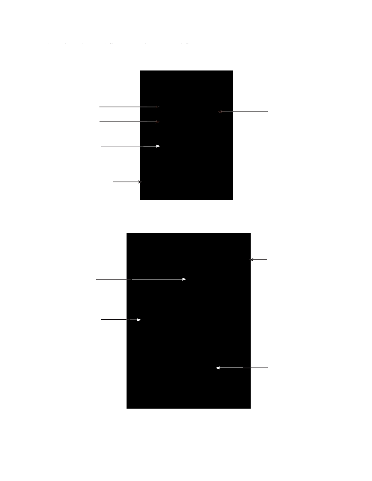
7
Cleaning pad
mounting unit
reservoir
Wand holder
ON/OFF button
Accessory outlet
Ground connector
Control panel
III -
EQUIPMENT CONTROLS
Power cord
Hand Wand hose
(electrical and solution
B
) FRONT AND BACK VIEW OF THE MACHINE
Page 9
C
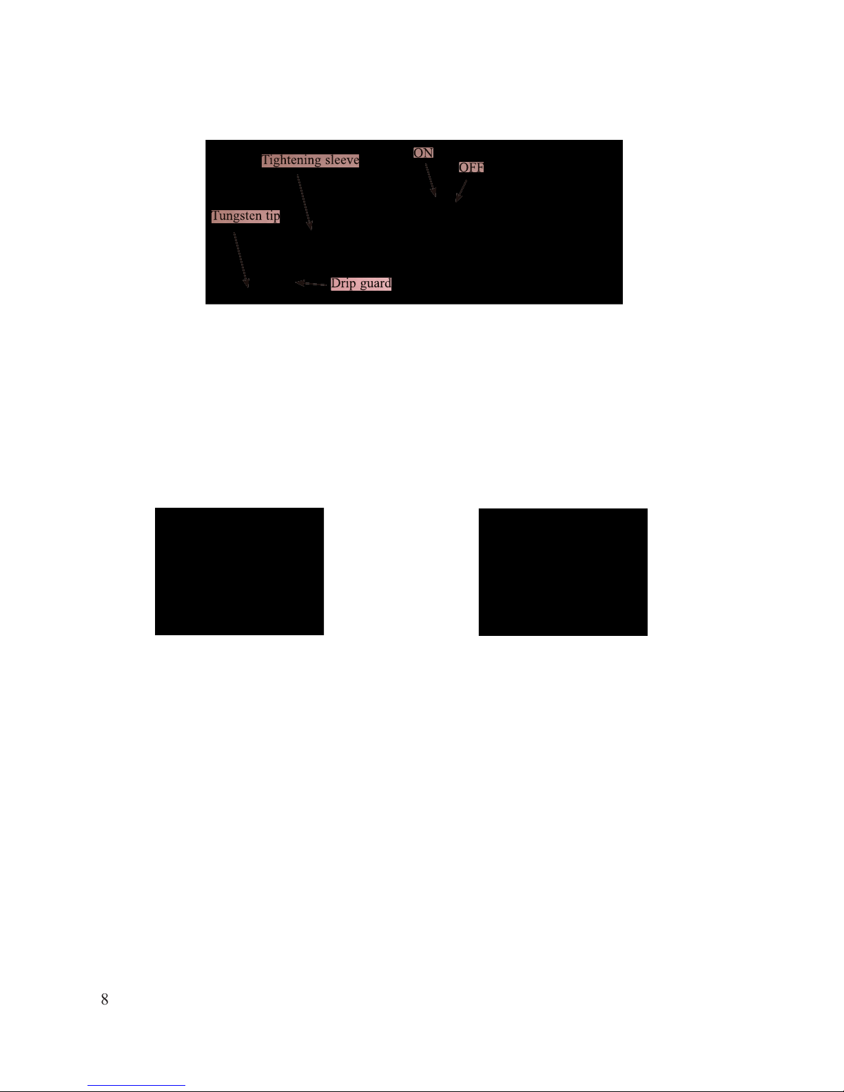
) WAND CONTROL BUTTONS
The ON butt
on is used to give power to the Tungsten tip. When the pumping mode is set to manual,
press the
ON button to activate the pump.
Press and keep the button pressed to get continuous flow of liquid.
How
ever, if the pumping mode is set to automatic, press the ON button once to activate the pump. To stop the
pump, press the OFF button. When finished working with the machine (in either mode) make sure to press
the
OFF button.
Once the ON button is pressed, there will be continuous power at the tip until the OFF button is pressed.
The Surfox 103 features a pivoting wand tip (tungsten tip). Simply loosen the plastic tightening sleeve and
turn the tip for hard to reach places, then re-tighten the sleeve (do not over-tighten).
EQUIPMENT CONTROLS
Tungsten tip
ON
OFF
Tightening sleeve
Drip guard
Page 10
IV - CONTROL PANEL
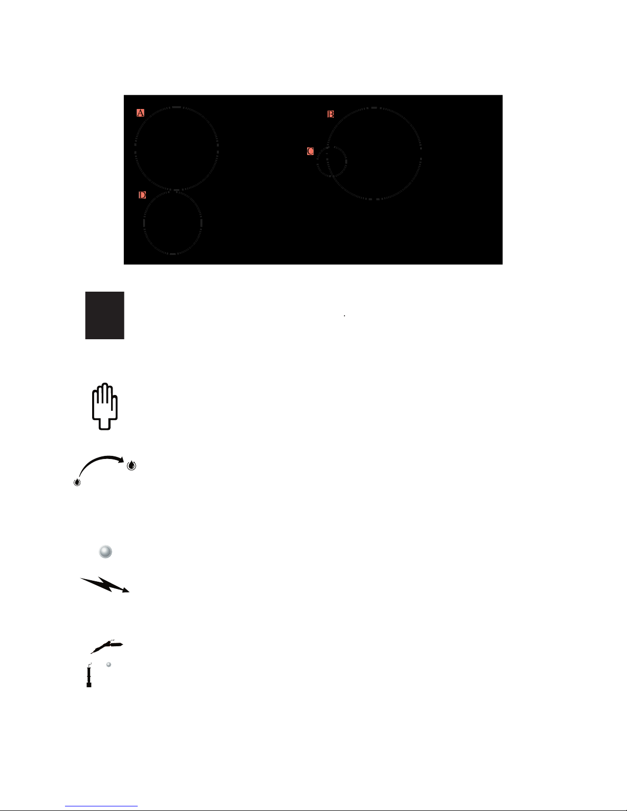
) MAIN POWER SWITCH
Turns the main power to the unit
ON
and
OFF
) SOLUTION PUMP SWITCH
Manual pumping mode.
Choose the manual pumping mode to control the amount of solution
pumping to the tip. Hold the Hand Wand ON button down to pump solution to the tip. Release
the ON button to stop the pumping cycle. Always use enough solution to keep the cleaning pad
wet. Too little solution will reduce the cleaning pad life.
Automatic pumping mode.
To start the automatic pumping mode, press the ON button on the
wand. Once it is activated, it will automatically pump the liquid. The quantity of liquid can be
selected from less to more. Pumping will continue in this mode until the OFF button is pressed.
C
) INDICATOR LIGHT
Hand Wand power
ON in
dicator.
The yellow light goes ON when the Hand Wand ON button
is pressed and there is power to the tip. Power to the tip is OFF when the Hand Wand OFF
button is pressed.
) ACCESSORY OUTLET
Outlet for optional Mini Wand or Marking Wand.
The Marking Wand is used to permanently
etch your company name, logo, part number or other desired information onto any metal surface.
The Mini Wand is used to access hard to reach areas for cleaning and passivating, which are too
small for the Hand Wand.
9
IV -
A
C
Page 11
V - START-UP P
ROCEDURE
A) WHAT IS INCLUDED IN THE BOX
1- Surf
chine
2- Hand Wand and connecting hose
3
- Ground clamp
4- Accessory kit contai
ning:
- 3 cleaning pads
- 1 PTFE clamping ring
- 1 cleaning boot
- 1 x 2.5mm hexagonal key for changing
Tungsten cleaning tips
B) FILLING THE RESERVOIR:
Fill the reservoir in the back of the machine with Surfox-T solution. The reservoir holds 1.9L of Surfox-T
solution.
C) MOUNTING A CLEANING PAD
0
Insert cleaning pad with symbol
facing up.
Firmly press-in Tungsten tip.
Remove tip with installed pad
and retaining ring.
3
Reservoir
START-UP PRO
Page 12

) PLUGGING IN THE POWER CORD
When an ext
ension cord is needed, use w
ire size 14 (AWG) for up to 50 feet (1
5 meters) and size 12 (AWG)
for 50 to 100 feet (15 to 30 meters).
E
) PLUGGING IN THE GROUND CLAMP
Plug the ground clamp at the
front of the unit. Attach the clamp to the work piece being cleaned. The cleaning
and passivating process will not work if the part is not properly grounded.
START-UP PROC
EDURE
Ground clamp
Page 13

VI - USING THE HAND WAND TO CLEAN AND PASSIVATE
A
) SELECTING THE PROPER PUMPING MODE
Manual pumping mode.
Choose the manual pumping mode to control the amount of solution pumping to the
tip. Hold the Hand Wand ON button down to pump solution to the tip. Release the ON button to stop the
pumping cycle. Always use enough solution to keep the cleaning pad wet. Too little solution will reduce the
cleaning pad life.
Automatic pumping mode.
To start the automatic pumping mode, press the ON button on the wand. Once it is
activated, it will automatically pump the liquid. The quantity of liquid can be selected from less to more.
Note:
It is best to use the manual mode at first, until you become familiar with the
cleaning system.
B
) CLEANING AND PASSIVATING
To clean an
d passivate, press the Hand Wand ON button. Make sure the cleaning pad is sat
urated with
Surfox-T solution
before starting to work. If the cleaning pad is too dry, it will wear prematurely. Star
t
working when solution dr
ips from the c
leaning pad.
Do not press hard, let the electrochemical process do the work. Do not use the cleaning pad like an abrasive
pad.
WARNING!
W
hen using the machine for the first time there could be water in the system from factory
testing. Let 1 or 2 ounces drip into a disposal cup before cleaning.
C
) NEUTRALIZING (refer to the Surfox-N section on
page 1
9
)
lution using a soft clean cl
oth.
2- Spray Surfox
-N on the surface.
3- Wipe dry with anot
her soft c
lean cloth.
Manual mode
Automatic mode
Page 14

VII - USING THE MINI WAND (OPTIONAL)
TO CLEAN AND PASSIVATE
) MANUAL PUMPING MODE
The Mini Wand uses a manual pumping mode only. One (1) press equals one (1) pump. To pump more liquid,
press repeatedly.
) CLEANING AND PASSIVATING
Screw in Surfox-T solution 100ml tube onto the Mini Wand. Make sure the cleaning pad is saturated with
Surfox-T solution before starting to work. If the cleaning pad is too dry, it will wear prematurely. Start
working when solution drips from the cleaning pad.
Do not press hard, let the electrochemical process do the work. The cleaning pad is a bridge between the
machine and the weld. Do not use the cleaning pad like an abrasive pad.
C
) NEUTRALIZING (refer to the Surfox-N section on
page 1
9
):
1- Remove any excess Surfox-T solution using a soft clean cloth
2- Spray Surfox-N on the surface
3- Wipe dry with another soft clean cloth
) LIST OF SUPPLIES AND PART NUMBERS
Mini Wand kit part no.: 54-B 033
The kit includes:
6 per package
D (OPTIONAL) TO C
LEAN AND PASSIVATE
Page 15

VIII - USING THE MARKING WAND (OPTIONAL)
Use the Marking Wand to permanently etch your company name, logo, part number or other desired information
) PROCEDURE FOR MARKING
1- Di
p the Marking Wand in Surfox
-M soluti
on
until the pad is satura
ted. Surfox-M is a different solution than
Surfox-T, which is used in the cleaning and passivating process. Surfox-M is part number 54-B 053.
- Place the stencil into position.
5- Remove the stencil.
TIP!
For best results, always tape the stencil in place using masking tape before marking.
D (OPTIONAL)
onto the surface of stainless steel, aluminum, brass, copper or steel. Plug the Marking Wand into the accessory
outlet on the front panel.
3- Ground the work piece.
$FWLYDWHWKH21EXWWRQORFDWHGRQWKH&OHDQLQJ:DQG ��
4- Rub the Marking Wand over the top of the stencil with a firm, but light pressure. You can also use a
technique of dabbing the Marking Wand on the stencil.
Page 16

6- Neutralize the work piece with Surfox-N.
7- Neutralize the stencil with Surfox-N, rince with water and dry. Store the stencil between 2 sheets of cardboard
and keep in a dry place.
) MARKING WAND SUPPLIES AND PART NUMBERS
Marking kit part no.: 54-B 013
The kit includes:
ing pads
54-B 062 10 per package
5 temporary stencils 54-B 064 100 per package
D (OPTIONAL)
Page 17
IX - NEUTRALIZING
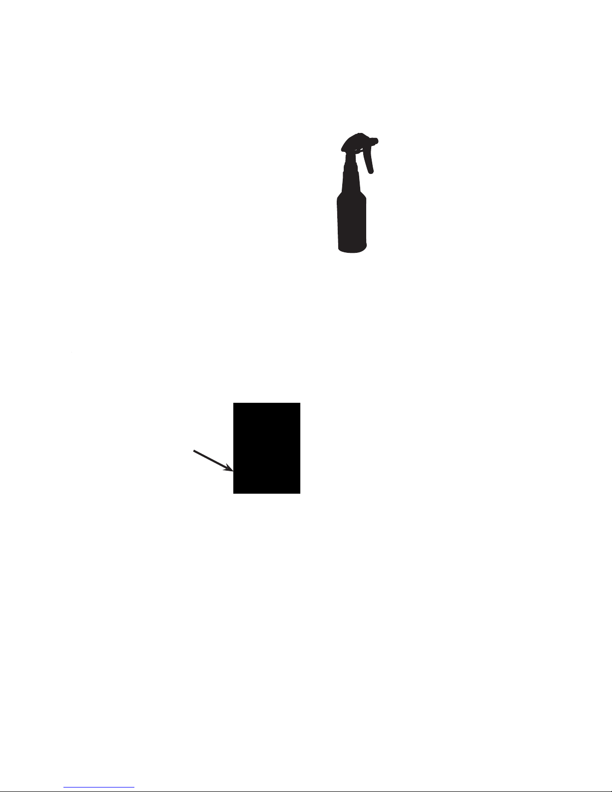
The
ution. It is a powerful ready-t
o-use
formula which leaves no residue, is non-toxic, solvent free, water-based and biodegradable.
o.: 54-A 023 (500ml sprayer)
Directions for ne
utralizing Sur
fox-T cleaning solution:
2- Spray Su
rfox-N on the surface.
3- Wipe dry with another
soft clean cloth.
For more information about this product, refer to MSDS S-03E.
WARNING!
WARNING!
Be sure to wipe off all excess Surfox-T from the surface and neutralize
otherwise the inorganic s
alt
from the phosphoric acid will adhere to the surface and cause deposits.
IX - NEUTRALIZING
Page 18
X - ACCESSORIES
A)
CLEANING TIPS
.
They are made from high
quality Tungsten allo
y material. Other materials will not resist
the harsh environment created by the electrochemical process.
Cleaning tips are available in several different shapes and sizes:
Tungsten Insert 90º:
For large flat surfaces and external angles.
Part number 48-R 133.
To be used with cleaning pad 54-B 001 (and clamp ring 54-B 002);
OR
To be used with cleaning boot 54-B 005 for internal corners
Tungsten Insert 60º:
For large internal surfaces and corners.
Part number 54-B 016.
To be used with cleaning boot 54-B 006. Easier to get into tight internal corners with the
60º insert than with the standard 90º insert.
Narrow tungsten insert 90º:
For narrow flat surfaces and external angles.
Part number 54-B 017.
To be used with cleaning pad 54-B 023 (and narrow clamp ring 54-B 020);
OR
To be used with cleaning boot 54-B 007 for internal corners.
Narrow T
ungsten Insert 60º:
For narrow internal surfaces and corners.
Part number 54-B 018.
To be used with cleaning boot 54-B 008. It is easier to get into tight internal corners
with the 60º insert than with the standard 90º insert.
WARNING!
When the insert is too worn, it can cause damage to the cleaning pads.
In this example of a worn insert, there are only two (2) contact points. All the current comes out of these two
(2) points. Because of the lower available cross section, the temperature will be higher at the two (2) points and
the cleaning pads may become damaged or wear out prematurely.
TIP!
Resurface the insert using a bench grinding wheel or angle grinder.
Note:
Be sure to install the O-ring located at the back of the insert
whenever they are changed.
X - ACCESSORIES
O-ring
Page 19

B) CLEANING PADS.
Cleaning pads are used on flat surfaces and external angles. They can also be used for
internal corners or as a first step, as they clean much faster than cleaning boots.
The cleaning pads are made from specially engineered polymer comprised of two (2) separate layers: one
internal rigid layer which is in contact with the insert for increased heat and chemical resistance, and one soft
external layer which is soft so that it will not damage or scratch the work piece during the cleaning operation.
For longer life, remove the cleaning pad and neutralize with Surfox-N
at the end of each working day
Cleaning pads are available in two (2) sizes:
Cleaning pad:
For large flat surfaces and external angles.
Part number 54-B 001.
To be used with tungsten insert 48-R 133 (and clamp ring 54-B 002).
Narrow cleaning pad:
For narrow flat surfaces and external angles.
Part number 54-B 023.
To be used with narrow tungsten insert 54-B 017 (and narrow clamp ring 54-B 020) .
X - ACCESSORIES
Page 20

C)
CLEANING BOOTS.
Cleaning
boots are made from a specially engineered polymer. They are composed of
one rigid layer which is very thin and durable, but not very absorbent (does not hold liquid). This may require
additional Surfox-T solution to keep the boot wet during cleaning.
They are used for internal angles or tight corners because they are thinner
and reduce the chance of arcing.
Since they
wrap around the insert, they avoid short circuits (arcing).
Several shapes and sizes are available:
Cleaning boot:
For large flat internal surfaces or angles.
Part number 54-B 005.
To be used with tungsten insert 48-R 133.
Narrow Cleaning boot:
For narrow flat internal surfaces or angles.
Part number 54-B 007.
To be used with tungsten insert 54-B 017.
Cleaning boot 60º:
For large internal corners or angles.
Part number 54-B 006.
To be used with tungsten insert 54-B 016.
Narrow Cleaning boot 60º:
For narrow internal corners or angles.
Part number 54-B 008.
To be used with tungsten insert 54-B 018.
X - ACCESSORIES
Page 21

D) PTFE CLAMP
RINGS
.
PTFE clamp rings are designed to hold the cleaning pads on the tungsten inserts.
They are available in two (2) sizes:
Clamp ring:
Part number 54-B 002.
To be used with tungsten insert 48-R 133 and cleaning pad 54-B 001.
Narrow clamp ring:
Part number 54-B 020.
To be used with tungsten insert 54-B 017 and cleaning pad 54-B 023.
E) SURFOX-T SOLUTION.
designed to be used only in
Walter Surfox cleaning systems.
Part number 54-A 005 (4 x 1.5L bottles per case)
WARNING!
Do not reuse Surfox-T solution after it has gone through the Surfox unit for cleaning. Used
solution loses its cleaning effectiveness, while the "waste" liquid can become contaminated with dirt and
particles. If these unwanted particles are put back into the unit, they can cause mechanical failure to the
pump, check valve and other internal components.
20
X - ACCESSORIES
Page 22

XI - SAFETY FEATURES
A) SPARKS ON THE TIP / WORK PIECE
To avoid short circuits (arcing), the machine automatically stops when the insert touches the work piece (metal
to metal contact). If the voltage sharply increases creating a short, the system will automatically cut the power
to the tip to avoid any damage to the equipment.
To restart the machine, simply press the Hand Wand ON button.
WARNING!
To avoid drawing too much amperage and automatically stopping the power to the tip, make sure
that you touch only one surface at a time. The machine is set to work at a maximum of 10 Amps. If the
amperage goes above 10 Amps, the machine automatically shuts down.
B)
INTERNAL TEMPERATURE
To protect the internal components of the machine, there are temperature sensors inside the machine. If the
operating temperature is too high, the machine will shut down and restart by itself when the temperature
reaches an acceptable level. There is an internal fan inside the machine to keep all the components cool.
WARNING!
The inside temperature can increase for many reasons: high ambient temperature, lack of proper
air circulation around the machine, fluctuations in voltage, electrical set-up in the shop, etc.
C
) WELDS THAT CANNOT BE CLEANED
I
f the area around the weld is b
lack (not blue) from contamination, this is a problem of high heat generated
during the welding process. The contaminated areas do not
conduct electricity. If there is no condu
ctivity in
the material, the Surfox system cannot work.
If there are two (2) w
elds on top of the other, the structure of the material has been seriously altered. These
areas ma
y not be cleaned.
The quality of the weld is critical
Example: On a flat surface, the amperage is around 8
Amps. The contact surface area is relatively small.
Example: An internal angle, which if you touch 2
sides simultaneously, the contact surface area is
doubled, amperage goes above 10 Amps and the
machine stops.
2
XI - SAFETY FEATURES
Page 23

XII - TECHNICAL DATA
MODEL: SURFOX 103
PART NUMBER: 54-D 113
INPUT VOLTAGE: 120 V, 50/60 Hz
OUTPUT VOLTAGE: 30 V, AC
INPUT CURRENT: 3 Amps
OUTPUT CURRENT: 10 Amps, AC
MAX. OUTPUT VOLTAGE: 33 V, AC
DIMENSIONS: 470mm x 380mm x 250mm
(18.5" x 15" x 9.75")
RESERVOIR CAPACITY: 1.9 L
WEIGHT: 16.8 kg (37 lbs.)
2
2
XII - TECHNICAL DATA
Page 24

XII - WA
RRANTY AND SERVICE
A) WARRANTY POLICY
All
WALTER
Surfox cleaning systems and accessories are inspected and tested before shipment and are
warranted to be free from any defect in material and faulty workmanship. Should any malfunction occur within
six (6) months from the date of original purchase, return the complete system prepaid with proof of purchase,
to the nearest
WALTER
Factory or Authorized Service Center. If an examination shows that the malfunction
was caused by defective material or faulty workmanship,
WALTER
will repair (or at our option, replace the
unit) without charge. This warranty does not apply when; normal maintenance is required, repairs or
replacements have been made or were attempted by anyone other than
WALTER
authorized service personnel,
and does not cover any damage caused by accidents, modifications, use of improper accessories, abuse or
misuse, which also includes overloading the tool beyond its rated capacity as well as its continued use after
partial failure. No other warranty, written or verbal, is authorized.
In no event shall
WALTER
be liable for any indirect, incidental or consequential damages from the sale of the
product. This disclaimer applies both during and after the term of this warranty.
This warranty gives you specific rights. The provisions contained in this warranty are not intended to limit,
modify, take away from, disclaim or exclude any warranties set forth in any Provincial or State legislation. To
the extent required by law, the provisions in any Provincial, State or Federal legislation with respect to
warranties take precedence over the provisions in this warranty.
B) WHERE TO GET SERVICE
CANADA
MONTREAL: 5977 Trans Canada Highway Tel: (514) 630-2801
Pointe-Claire, QC H9R 1C1 Fax: (514) 630-2825
TORONTO: 151 Superior Blvd., Unit 12 Tel: (905) 795-8555
Mississauga, ON L5T 2L1 Fax: (905) 795-8558
VANCOUVER: 1-1595 Cliveden Avenue Tel: (604) 540-4777
Delta, BC V3M 6M2 Fax: (604) 540-4778
U.S.A.
HARTFORD: J. Walter Inc. Tel: (860) 724-0321
141 Locust Street Fax: (860) 560-7300
Hartford, CT 06114-1504
MEXICO
MONTERREY:
Walter de Mexico, S.A. de C.V. Tel: (01)
81-10-91-81
Av. 1 de Mayo 3921 Fax: (01) 86
-75-
Burocratas del Estado e-mail:
fomexico@walter.ca
For the location of an authorized service center closest to you in Canada, call toll free 1-888-JWALTER
(1-888-592-5837). In the USA, call toll free 1-866-592-5837. Visit our web site:
www.walter.com
2
3
XII - WARRANTY AND SERVICE
Page 25
SPARE PARTS LIST
LISTE DE PIÈCES
LISTA DE PARTES
Page 26
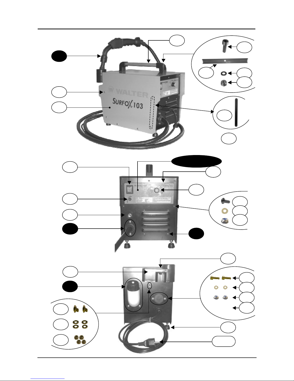
WALTER SURFOX 103
Spare parts list / Liste de pièces / Lista de Partes
1
20
19 10 15 14 16
B
C
11 - 12 -13
17 18
A
9 8 1 2
6 3 4 5 7
D
21
26 - 27
22 25 23 17 18 24 17 28 18
Page 27
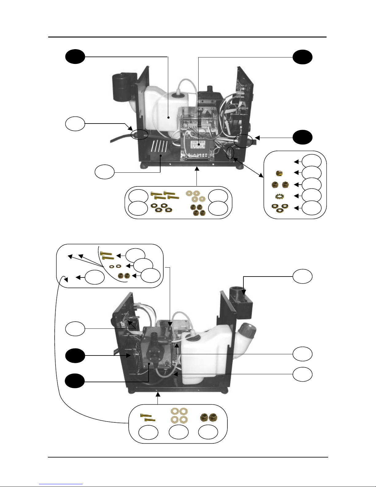
WALTER SURFOX 103
Spare parts list / Liste de pièces / Lista de Partes
2
B
41
F
40
39 22 35 33 31 38 23 17 18 37
C D
36
35 34 33
3129 30 31 32 33
E
Page 28
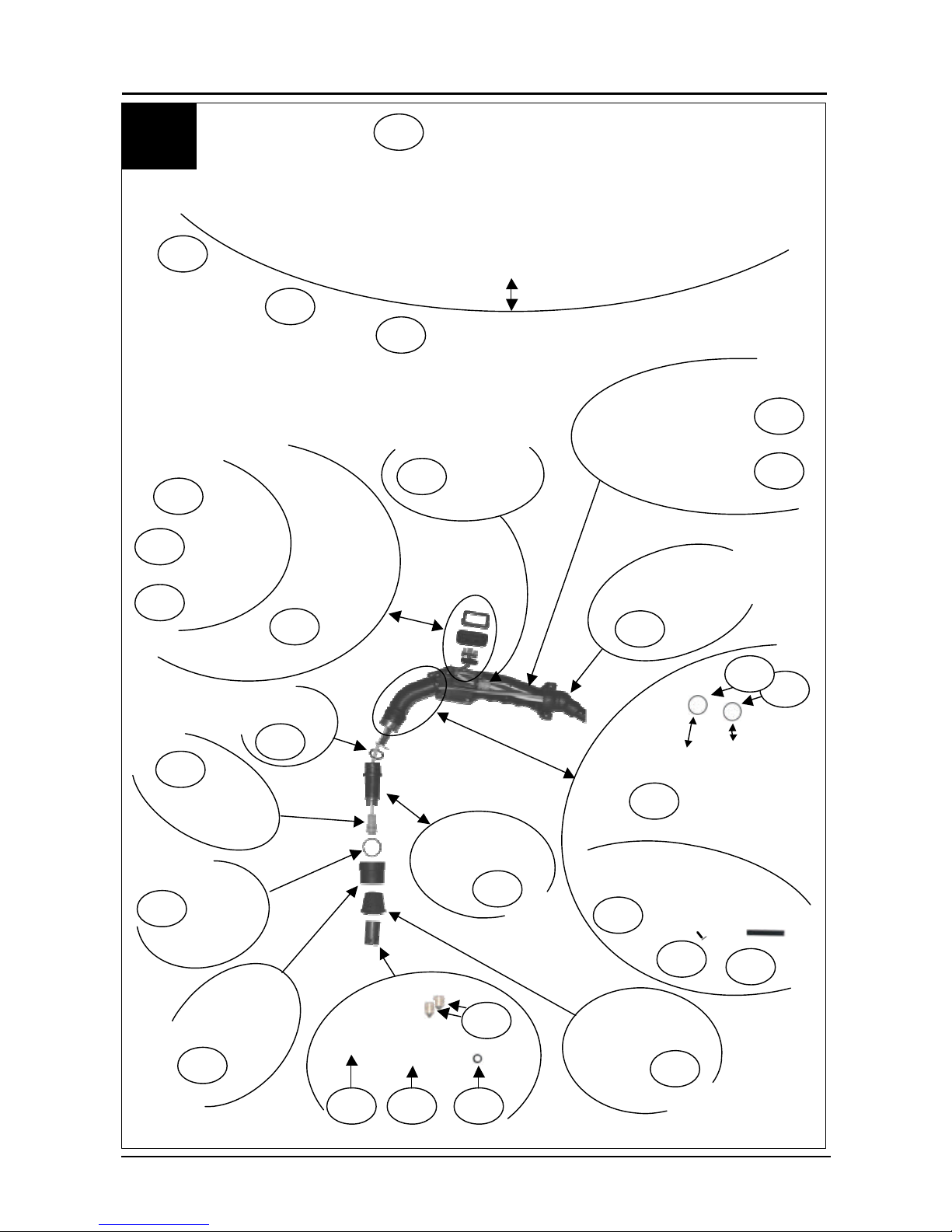
WALTER SURFOX 103
Spare parts list / Liste de pièces / Lista de Partes
3
A
42 45 46 48 47 50 66 64 65 62 63 61 51 39 44 43 60 55 53 57 67 58 56 55 54 52 59 49
Page 29
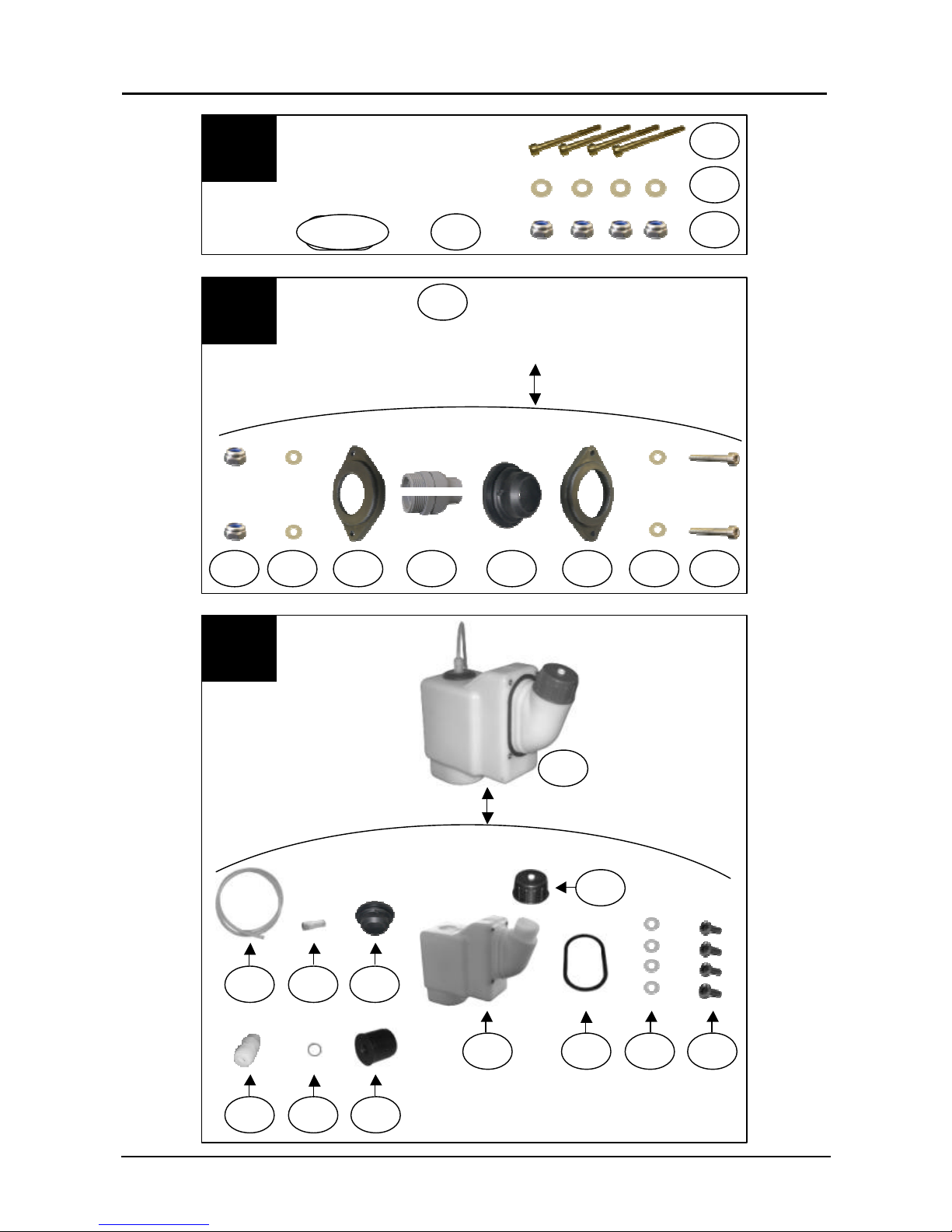
WALTER SURFOX 103
Spare parts list / Liste de pièces / Lista de Partes
4
C
18
17 76 75 74 73 17 77 72 70
B
18 71 17
68 - 69
D
49
86 85 83 82
3384 81 40 79 78 80
Page 30
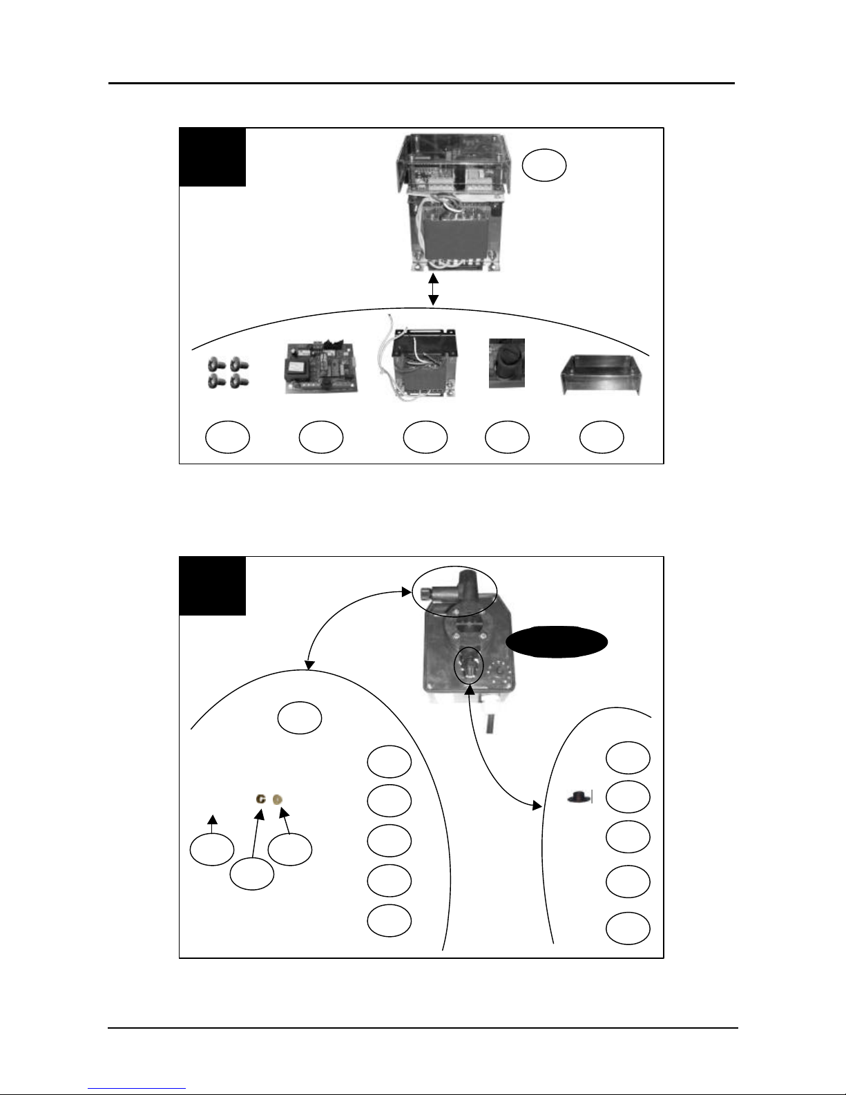
WALTER SURFOX 103
Spare parts list / Liste de pièces / Lista de Partes
5
98
G
95
99 98 96 97
92 - 93
98
94 91
F
28
90 88 89 87
Page 31
WALTER SURFOX 103
Spare parts list / Liste de pièces / Lista de Partes
6
Nr. Walter # DESCRIPTION Price
1 48-R 312
HANDLE
POIGNÉE
MANIJA
2 48-S 114
SCREW 8X30 MM
VIS 8X30 MM
TORNILLO 8 X 30 MM
3 48-R 313
“C” REINFORCEMENT
RENFORCEMENT EN “C”
REFUERZO EN "C"
4 48-K 106
STAINLESS STEEL WASH ER 8X16 MM
RONDELLE EN INOX 8X16 MM
ARANDELA INOX
5 48-K 419
SELF-LOCKING NUT M8
ÉCROU DE VERROUILLAG E AUTOMATIQUE M8
TUERCA AUTOBLOCANTE M 8
6 48-R 314
FIXATION PLATE
PLAQUE DE FIXATIO N
PLACA DE FIJACIÓN
7 48-R 136
GROUND CABLE
CÂBLE DE MISE À LA TERRE
PINZA DE TIERRA
8 48-R 315
SURFOX 103 COVER
COUVERCLE SURFOX 103
TAPA COVERTORA SURFO X 103
9 48-S 128
SCREW 5X10 MM
VIS 5X10 MM
TORNILLO 5 X 10 MM
10 48-R 105
MAIN SWITCH
INTERRUPTEUR PRINCIPAL
INTERRUPTOR PRINCIPAL
11 48-R 317
SURFOX 103 LABEL (CAN/USA/MEX)
ÉTIQUETTE SURFOX 103 (CAN/USA/MEX)
ETIQUETA SURFOX 103 (CAN/USA/MEX)
12 48-R 318
SURFOX 103 LABEL (ARG/BRA/CIL)
ÉTIQUETTE SURFOX 103 (ARG/BRA/CIL)
ETIQUETA SURFOX 103 (ARG/BRA/CIL)
13 48-R 319
SURFOX 103 LABEL (GER)
ÉTIQUETTE SURFOX 103 (GER)
ETIQUETA SURFOX 103 (GER)
14 48-R 320
CONTROL PANEL
PANNEAU DE CONTRÔLE
PANEL DE CONTROL
15 48-R 321
SELECTOR KNOB
BOUTON DE SÉLECTION
LLAVE SELECTORA
Page 32
WALTER SURFOX 103
Spare parts list / Liste de pièces / Lista de Partes
7
16 48-S 117
SCREW 4X10 MM
VIS 4X10 MM
TORNILLO 4 X 10 MM
17 48-K 107
STAINLESS STEEL WASH ER 4X8 MM
RONDELLE EN INOX 4X8 MM
ARANDELA INOX 4 X 8 MM
18 48-K 420
SELF-LOCKING NUT M4
ÉCROU DE VERROUILLAG E AUTOMATIQUE M4
TUERCA AUTOBLOCANTE M 4
19 48-R 109
GROUND CONNECTOR
CONNECTEUR DE MISE À LA TERRE
CONECTOR DE TIERRA
20 48-R 254
MARKER OUTLET
SORTIE DU MARQUEUR
TOMA CORRIENTE 30 VOLTS
21 48-R 245
WAND HOLDER & PAD MO UNTING FIXTURE
SUPPORT DE BAGUETTE ET DE MONTAGE DE TAMPON
ALOJAMIENTO DE TORCHA
22 48-S 118
SCREW 6X20 MM
VIS 6X20 MM
TORNILLO 6 X 20 MM
23 48-S 120
SCREW 4X16 MM
VIS 4X16 MM
TORNILLO 4 X 16 MM
24 48-R 322
COVER
COUVERCLE
COVERTOR
25 48-R 323
FEET
PATTES
PIE / SOPORTE
26 48-Z 202
CORD SET 120 V
CÂBLE 120 V
CABLE DE ALIMENTACIÓ N 120 V
27 48-R 205
CORD SET 230 V
CÂBLE 230 V
CABLE DE ALIMENTACIÓ N 230 V
28 48-S 129
SCREW 4X10 MM
VIS 4X10 MM
TORNILLO 4 X 10 MM
29 48-S 130
SCREW 5X35 MM
VIS 5X35 MM
TORNILLO 5 X 35 MM
30 48-R 326
STAINLESS STEEL SLEEVE 5X8X6 MM
MANCHON EN INOX 5X8X6 MM
SUPLEMENTO INOX 5 X 8 X 6 MM
Page 33
WALTER SURFOX 103
Spare parts list / Liste de pièces / Lista de Partes
8
31 48-R 288
SELF-LOCKING NUT M5
ÉCROU DE VERROUILLAG E AUTOMATIQUE M5
TUERCA AUTOBLOCANTE MS
32 48-K 108
LOCK WASHER 5X10 MM
RONDELLE DE VERROUILLAGE 5X10 MM
ARANDELA 5 X 10 MM
33 48-K 111
STAINLESS STEEL WASH ER 5X10 MM
RONDELLE EN INOX 5X10 MM
ARANDELA 5 X 10 MM
34 48-R 289
STAINLESS STEEL WASH ER 5X15 MM
RONDELLE EN INOX 5X15 MM
ARANDELA 5 X 15 MM
35 48-S 121
SCREW 5X16 MM
VIS 5X16 MM
TORNILLO 5 X 16 MM
36 48-R 327
SURFOX 103/203 BASE
BASE SURFOX 103/203
BASER SURFOX 103/203
37 48-R 106
STRAIN RELIEF CONNEC TOR
CONNECTEUR POUR BRIDE DE CÂBLE
PRENSA CABLE
38 48-R 328
PUMP SUPPORT
APPUI DE POMPE
SOPORTE DE BOMBA
39 48-R 329
TEFLON HOSE 2X4 MM (LENGTH 4,8 M)
TUYAU DE TÉFLON 2X4 MM (LONG 4,8 M)
TUBO DE TEFLÓN 2 X 4 MM (LONG 4,8 M)
40 48-R 330
POLYETHYLENE HOSE 4X 6 MM (LENGTH 800 MM)
TUYAU DE POLYÉTHYLÈNE 4X6 MM (LONG. 800 MM)
TUBO DE POLIETILENO 4 X 6 MM (LONG. 800 MM)
41 48-R 255
CONTROL PANEL PCB
CIRCUIT IMPRIMÉ DE PANNEAU DE CONTRÔLES
CIRCUITO IMPRESO DE PANEL DE CONTROL
42 48-R 153
WAND ASSEMBLY W/O TUNGSTEN TIP
ASSEMBLAGE DE BAGUETTE SANS EMBOUT DE TUNGSTÈNE
TORCHA
43 48-R 331
FP15 HOSE (LENGTH 4 M)
TUYAU FP15 (LONG. 4 M)
TUBO (LONG. 4 M)
44 48-R 332
ELECTRIC CABLE 3X0,5 (LENGTH 4,8 M)
CÂBLE ÉLECTRIQUE 3X0,5 (LONG. 4,8 M)
CABLE DE TORCHA 3 X 0,5 (LONG. 4,8 M)
45 48-R 307
MICRO-SWITCH COMPLET E
MICRO-INTERRUPTEUR COMPLET
MICRO INTERRUPTOR COMPLETO
Page 34
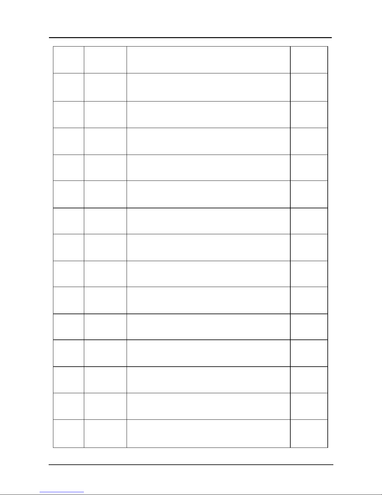
WALTER SURFOX 103
Spare parts list / Liste de pièces / Lista de Partes
9
46 48-R 177
FLANGE
BRIDE
BRIDA
47 48-R 178
MICRO-SWITCH COVER
COUVERCLE POUR MICRO -INTERRUPTEUR
COBERTOR PARA MICRO INTERRUPTOR
48 48-R 179
MICRO-SWITCH
MICRO-INTERRUPTEUR
MICRO INTERRUPTOR
49 48-R 180
STRAIN RELIEF CONNEC TOR
CONNECTEUR POUR BRIDE DE CÂBLE
PRENSA CABLE DE TORCHA
50 48-R 181
WAND HANDLE
POIGNÉE DE BAGUETTE
EMPUÑADURA DE TORCHA
51 48-S 122
SCREW 3X12 MM
VIS 3X12 MM
TORNILLO 3 X 12 MM
52 48-R 183
WAND CONNECTOR
CONNECTEUR POUR BAGUETTE
CONECTOR DE MANGUERA
53 48-R 185
SLEEVE WITH CONDUCTO R
MANCHON AVEC CONDUCT EUR
SUPLEMENTO CON CABLE
54 48-R 187
VITON O-RING 27X1,5 MM
JOINT EN O EN VITON 27X1,5 MM
O-RING 27 X 1,5 MM
55 48-R 186
VITON O-RING 26,7X1, 78 MM
JOINT EN O EN VITON 26,7X1,78 MM
O-RING 26,7 X 1,78
56 48-R 333
SLEEVE
MANCHON
CODO DE TORCHA
57 48-R 334
CONDUCTOR (LENGTH 4, 8 M)
CONDUCTEUR (LONG. 4, 8 M)
CONDUCTOR (LONG. 4,8 M)
58 48-R 335
SHRINK TUBE
TUBE RÉTRÉCISSANT
TUBO TERMORESISTENTE
59 48-R 192
INTAKE SLEEVE
MANCHON D’ASPIRATION
TERMINAL DE ASPIRACIÓN
60 54-B 003
DRIP GUARD
GARDE D’ÉGOUTTEMENT
PROTECCIÓN ANTIDERRAME
Page 35
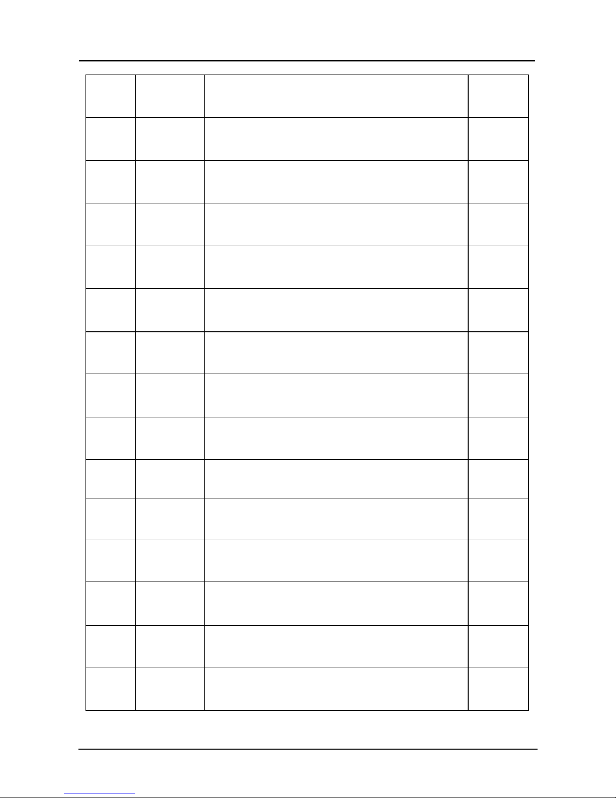
WALTER SURFOX 103
Spare parts list / Liste de pièces / Lista de Partes
10
61 48-S 530
SET SCREW M5X6
ENSEMBLE DE VIS M5X6
TORNILLOS 5 X 6 MM
62 48-R 113
VITON O-RING 3X1 MM
JOINT EN O EN VITON 3X1 MM
O-RING 3 X 1 MM
63 48-R 174
INSERT HOLDER
SUPPORT D’INSERT
PORTA INSERTO
64 48-R 175
VITON O-RING 16X1 MM
JOINT EN O EN VITON 16X1 MM
O-RING 16 X 1 MM
65 48-R 188
TIGHTENING SLEEVE
MANCHON DE SERRAGE
TUERCA PLASTICA DE PUNTERA
66 48-R 203
CHECK VALVE COMPLETE
VALVE DE RETENUE COMPLÈTE
VALVULA COMPLETA
67 48-R 189
VITON O-RING 18,6X2, 4 MM
JOINT EN O EN VITON 18,6X2,4 MM
O-RING 18,6 X 2,4 MM
68 48-R 336
COOLING FAN 120 V
VENTILATEUR 120 V
VENTILADOR 120 V
69 48-R 337
COOLING FAN 230 V
VENTILATEUR 230 V
VENTILADOR 230 V
70 48-R 338
PROTECTIVE GRID FOR FAN
GRILLE DE PROTECTION POUR VENTILATEUR
REJILLA PROTECTORA
71 48-S 123
SCREW 4X50 MM
VIS 4X50 MM
TORNILLO 4 X 50 MM
72 48-R 339
CONNECTION FOR HOSE
CONNECTEUR POUR TUYAU
CONECTOR DE MANGUERA
73 48-R 340
COVER
COUVERCLE
COVERTOR
74 48-R 107
REVOLVING CONNECTION FOR HOSE
CONNECTION PIVOTANTE POUR TUYAU
CONECCIÓN DE MANGUERA
75 48-R 341
RUBBER SLEEVE
MANCHON DE CAOUTCHOU C
SEPARADOR DE GOMA
Page 36
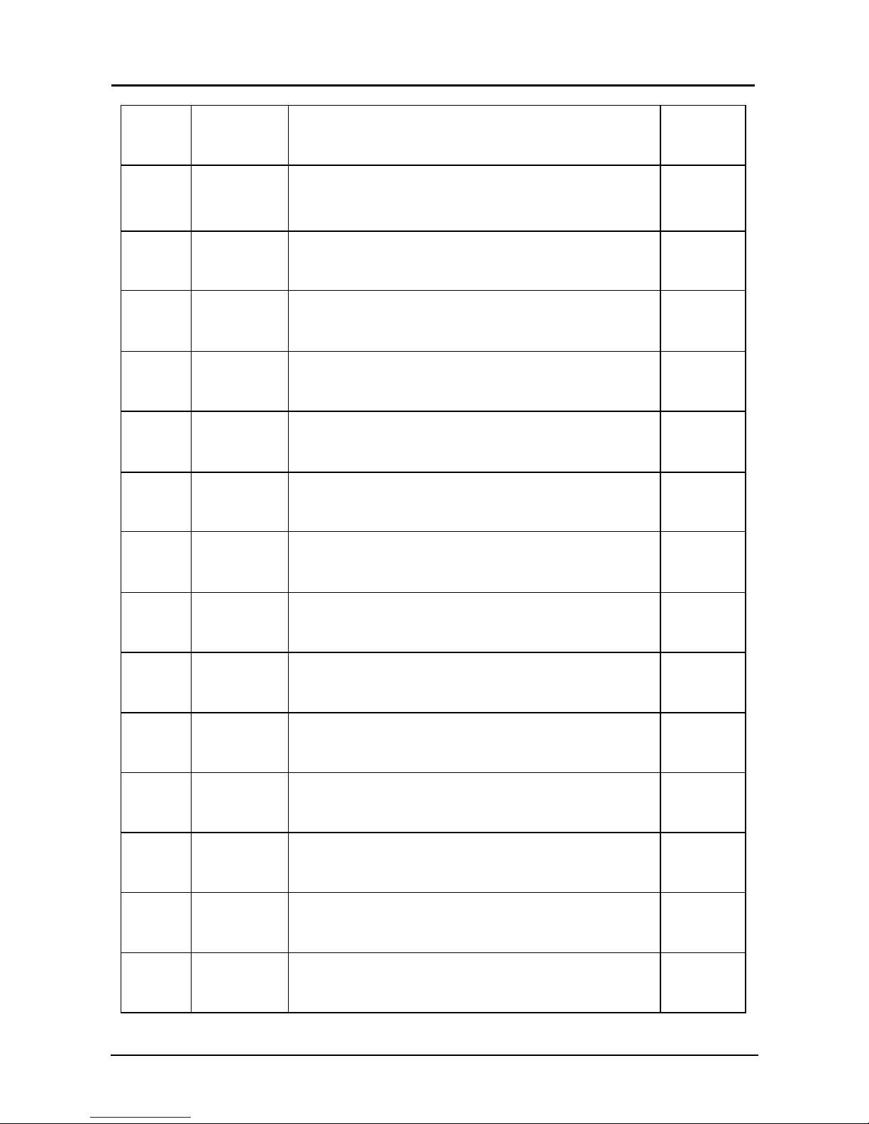
WALTER SURFOX 103
Spare parts list / Liste de pièces / Lista de Partes
11
76 48-R 342
COVER
COUVERCLE
COVERTOR
77 48-S 124
SCREW 4X30 MM
VIS 4X30 MM
TORNILLO 4 X 30 MM
78 48-R 343
COMPLETE TANK 103
RÉSERVOIR COMPLET 103
TANQUE COMPLETO 103
79 48-R 206
FILTER Ø 6 MM
FILTRE Ø 6 MM
FILTRO DIAM. 6MM
80 48-R 344
RUBBER SLEEVE
MANCHON DE CAOUTCHOU C
SEPARADOR DE GOMA
81 48-R 197
O-RING 12X1 MM
JOINT EN O 12X1 MM
O-RING 12 X 1 MM
82 48-R 345
FLANGE
BRIDE
BRIDA
83 48-R 346
TANK 103/203
RÉSERVOIR 103/203
TANQUE 103/203
84 48-R 347
TANK CAP
BOUCHON DU RÉSERVOIR
TAPÓN DE TANQUE
85 48-R 348
GASKET FOR TANK 103/ 203
JOINT D’ÉTANCHÉITÉ POUR RÉSERVOIR 103/203
JUNTA DE TANQUE 103/ 203
86 48-S 125
SCREW 5X8 MM
VIS 5X8 MM
TORNILLO 5 X 8 MM
87 48-R 349
TRANSFORMER WITH PC BOARD 120/230 V
TRANSFORMEUR AVEC CI RCUITS IMPRIMÉS 120/230 V
TRANSFORMADOR CON PLACA 120/230 V
88 48-R 350
PC BOARD 120/230 V
PANNEAU DE CIRCUITS IMPRIMÉS 120/230 V
PLACA ELECTRONICA 120/230 V
89 58-R 351
TRANSFORMER
TRANSFORMEUR
TRANSFORMADOR
90 48-R 290
FUSE 10 AMP
FUSIBLE 10 AMP
FUSIBLE 10 AMP
Page 37
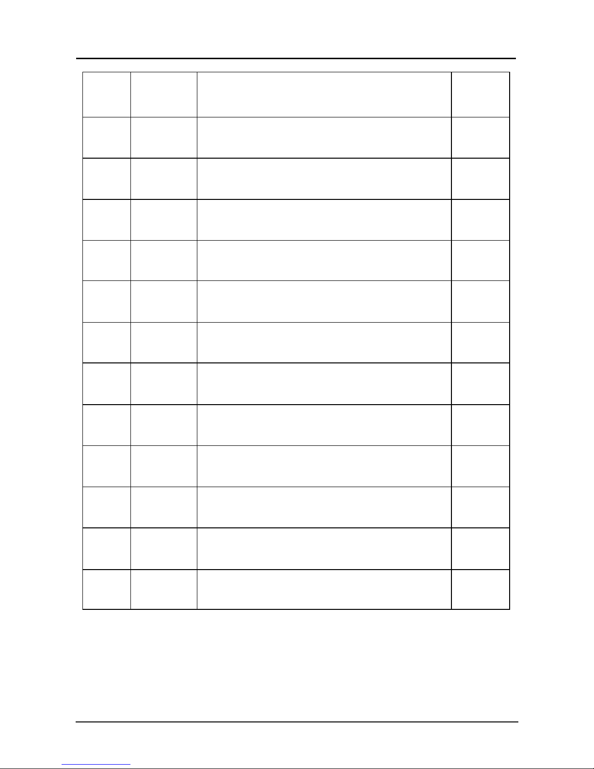
WALTER SURFOX 103
Spare parts list / Liste de pièces / Lista de Partes
12
91 48-R 352
PROTECTION FOR PC BOARD
PROTECTION POUR PANNEAU DE CIRCUITS IMPRIMÉS
PROTECCION DE TRANSF ORMADOR
92 48-R 233
PUMP 120V
POMPE 120V
BOMBA 120 V
93 48-R 234
PUMP 230V
POMPTE 230V
BOMBA 230 V
94 48-R 353
PUMP REVOLVING CONNECTION
CONNECTION POUR POMPE PIVOTANTE
CONECTOR
95 48-R 324
PUMP CONNECTION FOR HOSE
CONNECTION DE LA POMPE POUR TUYAU
CONECTOR
96 48-R 194
SPLIT SLEEVE
MACHON FENDU
SEPARADOR DIAM. 4
97 48-R 195
SPLIT SLEEVE
MANCHON FENDU
SEPARADOR DIAM. 4
98 48-R 310
VITON O-RING 15,6X1,78 MM
JOINT EN O DE VITON 15,6X1,78 MM
O-RING 15,6 X 1,78 MM
99 48-R 325
REVOLVING CONNECTOR
CONNECTEUR PIVOTANT
CONECTOR
100 48-R 309
DUCKBILL VALVE
VALVE DUCKBILL
VALVULA DE BOMBA
101 48-R 308
VALVE SEAT
SIÈGE DE VALVE
ASIENTO DE VALVULA
102 48-R 316
FITTING FOR HOSE 4X6 MM
RACCORD POUR TUYAU 4X6 MM
CONECTOR PARA TUBO PLASTICO
103 48-R 171
NUT FOR HOSE 4X6 MM
ÉCROU POUR TUYAU 4X6 MM
TUERCA PLASTICA 4X6 MM
Page 38
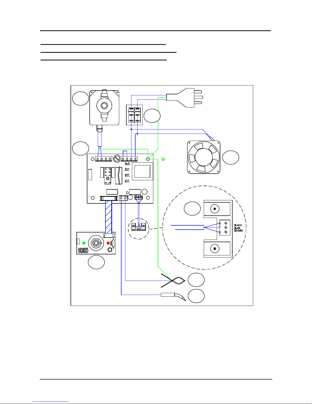
WALTER SURFOX 103
Spare parts list / Liste de pièces / Lista de Partes
13
SURFOX 103 – ELECTRICAL DIAGRAM
SURFOX 103 – DIAGRAMME ÉLECTRIQUE
SURFOX 103 – DIAGRAMA ELÉCTRICO
1
2 3 4 5 6 7 8
 Loading...