

Walter MINI PS 6163B, IRONMAN 6560A, BIG PS 6263B, IRONMAN PS 6563A, QUICK-STEP FINISHER 6275B Operating Instructions Manual
...
1
06/02/2018
En Operating Instructions 6
Fr Mode d'emploi 17
Es Instrucciones de manejo 23
Made in Germany
www.walter.com
MINI 4.5”
6161K
30-A 161
MINI PS 4.5”
6163B
30-A 163
MINI PLUS 5"
6255J
30-A 255
SUPER 5”
6150I
30-A 150
SUPER 5” PS
6153B
30-A 153
PRO 5”
6157A
30-A 157
BIG 6”
6260J
30-A 260
BIG 6” PS
6263B
30-A 263
IRONMAN
IRONMAN PS
QUICK-STEP FINISHER
6560A
6563A
6275B
30-A 560
30-A 563
30-A 275
2
3

4
QUICK-R -
✓ ✓ ✓ ✓ ✓ ✓ ✓ ✓ ✓ ✓ ✓
Electronic - - -
DYNAMAX
DIALSPEED
- - DYNAMAX DYNAMAX DYNAMAX DYNAMAX DYNAMAX
DYNAMAX
DIALSPEED
Ø in (mm) 4 1/2 (115) 4 1/2 (115) 5 (125) 5 (125) 5 (125) 5 (125) 6 (150) 6 (150) 6 (150) 6 (150) 6 (150)
M / l - / in
n min-1 10500 10500 11000 11000 11000 11000 9600 9600 9600 9600 7600
-1
(rpm)
P1 W 900 900 1550 1250 1250 1550 1700 1700 1750 1750 1550
P2 W 550 550 940 780 780 940 1040 1040 1070 1070 940
I120 V A 8,5 8,5 13,5 10,5 10,5 13,5 14,5 14,5 14,5 14,5 13,5
m lbs (kg) 4.6 (2,1) 4.6 (2,1) 5.5 (2,5) 5.3 (2,4) 5.3 (2,4) 5.5 (2,5) 5.5 (2,5) 6.2 (2,8) 5.5 (2,5) 6.2 (2,8) 5.5 (2,5)
ah,SG /Kh,SG m/s2 4,9/1,5 4,9/1,5 4,0 / 1,5 6,0/1,5 4,9/1,5 4,0 / 1,5 4,0 / 1,5 4,5 / 1,5 4,9 / 1,5 6,0 / 1,5 4,7/1,5
ah,D S/Kh,DS m/s2 <2,5/1,5 <2,5/1,5 3,0 / 1,5 <2,5/1,5 <2,5/1,5 3,0 / 1,5 3,0 / 1,5 4,2 / 1,5 4,0 / 1,5 4,9 / 1,5 2,5/1,5
ah,P /Kh,P m/s2 - - 3,6 / 1,5 - - - - - - - <2,5/1,5
QS Finisher
(6275)
2000-7600
5/8“-11 UNC
(10; 6,8; 6,8)
3/8; 1/4; 1/4
-
SUPER5 PS
(6153)
SUPER5
(6150)
2800-11000
-
-
IRONMAN PS
(6563)
IRONMAN
(6560)
PRO5
(6157)
MINI PS
(6163)
in (mm)
Specifications
nV
-
-
tmax1; tmax2 ; tmax3
BIG 6
(6260)
BIG 6 PS
(6263)
-
-
MINI
(6161)
-
MINI-PLUS
(6255)
5
B
C
A

En ENGLISH
6
Operating Instructions
1. Specified Use
The angle grinders, when fitted with original Walter accessories, are suitable for grinding, sanding,
abrasive cutting-off operations and wire brushing metal, concrete, stone and similar materials
without the use of water.
The QUICK-STEP FINISHER 6” is additionally suited for polishing work. We recommend using our
QUICK-STEP BIG-BUFF III polisher for demanding polishing work in continuous operation.
Machines with the designation DYNAMAXTM are particularly suited for working with wire brushes,
flap discs and sanding discs due to thumbwheel for speed selection.
The user bears sole responsibility for any damage caused by inappropriate use.
Generally accepted accident prevention regulations and the enclosed safety information must be
observed.
2. General Safety Instructions
For your own protection and for the protection of your electrical tool, pay attention to all
parts of the text that are marked with this symbol!
WARNING – Reading the operating instructions will reduce the risk of injury.
Pass on your electrical tool only together with these documents.
General Power Tool Safety Warnings
WARNING – Read all safety warnings and instructions. Failure to follow the warnings and
instructions may result in electric shock, fire and/or serious injury.
Save all warnings and instructions for future reference! The term "power tool" in the warnings refers to
your
mains-operated
(corded) power tool or battery-operated (cordless) power tool.
2.1 Work area safety
a) Keep work area clean and well lit. Cluttered or dark areas invite accidents.
b) Do not operate power tools in explosive atmospheres, such as in the presence of flammable liquids,
gases or dust. Power tools create sparks which may ignite the dust or fumes.
c) Keep children and bystanders away while operating a power tool. Distractions can cause you to lose
control.
2.2 Electrical safety
a) Power to ol plugs must match the outlet. Never modify the plug in any way. Do not use any adapter
plugs with earthed
(gr
ounded) power tools. Unmodified plugs and matching outlets will reduce risk of
electric shock.
b) Avoid body contact with earthed or grounded surfaces, such as pipes, radiators, ranges and
refrigerators. There is an increased risk of electric shock if your body is earthed or grounded.
c) Do not expose power tools to rain or wet conditions. Water entering a power tool will increase the risk
of electric shock.
d) Do not abuse the cord. Never use the cord for carrying, pulling or unplugging the power tool. Keep
cord away from heat, oil, sharp edges or moving parts. Damaged or entangled cords increase the risk of
electric shock.
e) When operating a power tool outdoors, use an extension cord suitable for outdoor use. Use of a cord
suitable for outdoor use reduces the risk of electric shock.

En ENGLISH
7
f) If operating a power tool in a damp location is unavoidable, use a residual current device (RCD)
protected supply. Use of an RCD reduces the risk of electric shock.
2.3 Personal safety
a) Stay alert, watch what you are doing and use common sense when operating a power tool. Do not
use a power tool while you are tired or under the influence of drugs, alcohol or medication. A moment
of inattention while operating power tools may result in serious personal injury.
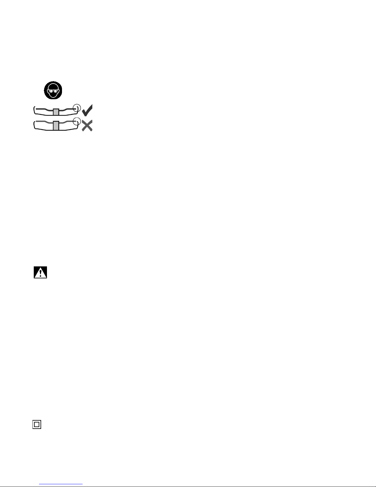
b) Use personal protective equipment. Always wear eye protection. Protective equipment such as dust
mask, non-skid safety shoes, hard hat, or hearing protection used for appropriate conditions will reduce
personal injuries.
c) Prevent unintentional starting. Ensure the switch is in the off-position before connecting to power
source and/or battery pack, picking up or carrying the tool. Carrying power tools with your finger on the
switch or energizing power tools that have the switch on invites accidents.
d) Remove any adjusting key or wrench before turning the power tool on. A wrench or a key left attached
to a rotating part of the power tool may result in personal injury.
e) Do not overreach. Keep proper footing and balance at all times. This enables better control of the power
tool in unexpected situations.
f) Dress properly. Do not wear loose clothing or jewellery. Keep your hair, clothing and gloves away
from moving parts.
Loose clothes,
jewellery or long hair can be caught in moving parts.
g) If devices are provided for the connection of dust extraction and collection facilities, ensure these
are connected and properly used. Use of dust collection can reduce dust-related hazards.
2.4 Power tool use and care
a) Do not force the power tool. Use the correct power tool for your application. The correct power tool
will do the job better and safer at the rate for which it was designed.
b) Do not use the power tool if the switch does not turn it on and off. Any power tool that cannot be
controlled with the switch is dangerous and must be repaired.
c) Disconnect the plug from the power source and/or the battery pack from the power tool before
making any adjustments, changing accessories, or storing power tools. Such preventive safety
measures reduce the risk of starting the power tool accidentally.
d) Store idle power tools out of the reach of children and do not allow persons unfamiliar with the
power tool or these instructions to operate the power tool. Power tools are dangerous in the hands of
untrained users.
e) Maintain power tools. Check for misalignment or binding of moving parts, breakage of parts and any
other condition that may affect the power tool's operation. If damaged, have the power tool repaired
before use. Many accidents are caused by poorly maintained power tools.
f) Keep cutting tools sharp and clean. Properly maintained cutting tools with sharp cutting edges are less
likely to bind and are easier to control.
g) Use the power tool, accessories and tool bits etc. in accordance with these instructions, taking into
account the working conditions and the work to be performed. Use of the power tool for operations
different from those intended could result in a hazardous situation.
2.5 Service
a) Have your power tool serviced by an authorized Walter service center. This will ensure that the safety
of the power tool is maintained.
3. Special Safety Instructions
3.1 Safety Warnings Common for Grinding, Sanding, Polishing (only for models 6255 and 6275), Wire
Brushing or Abrasive Cutting-Off Operat
ions:
a) This power tool is intended to function as a grinder, sander, and wire brush or
cut-off
tool. Read all
safety warnings, instructions, illustrations and specifications provided with this power tool. Failure to
follow all instructions listed below may result in electric shock, fire and/or serious injury. The QUICK-STEP
FINISHER 6” can also be used as polishing tool.
b) Operations such as polishing are not recommended to be performed with this power tool. Operations
for which the power tool was not designed may create a hazard and cause personal injury.

En ENGLISH
8
c) Do not use accessories which are not specifically designed and recommended by the tool
manufacturer. Just because the accessory can be attached to your power tool, it does not assure safe
operation.
d) The rated speed of the accessory must be at least equal to the maximum speed marked on the
power tool. Accessories running faster than their rated speed can break and fly apart.
e) The outside diameter and the thickness of your accessory must be within the capacity rating of
your power tool. Incorrectly sized accessories cannot be adequately guarded or controlled.
f) Threaded mounting of accessories must match the GRINDER spindle thread. For accessories
mounted by FLANGES, the arbour hole of the accessory must fit the locating diameter of the FLANGE.
Accessories that do not match the mounting hardware of the power tool will run out of balance, vibrate
excessively and may cause loss of control.
g) Do not use a damaged accessory. Before each use inspect the accessory such as abrasive wheels
for chips and cracks, backing pad for cracks, tear or excess wear, wire brush for loose or cracked
wires. If a power tool or accessory is dropped, inspect for damage or install an undamaged accessory.
After inspecting and installing an accessory, position yourself and bystanders away from the plane
of the rotating accessory and run the power tool at maximum no-load speed for one minute. Damaged
accessories will normally break apart during this test time.
h) Wear personal protective equipment. Depending on application, use face shield, safety goggles or
safety glasses. As appropriate, wear dust mask, hearing protectors, gloves and workshop apron
capable of stopping small abrasive or workpiece fragments. The eye protection must be capable of
stopping flying debris generated by various operations. The dust mask or respirator must be capable of
filtering particles generated by your operation. Prolonged exposure to high intensity noise may cause hearing
loss.
i) Keep bystanders a safe distance away from work area. Anyone entering the work area must wear
personal protective equipment. Fragments of workpiece or of a broken accessory may fly away and cause
injury beyond immediate area of operation.
j) Hold the power tool by insulated gripping surfaces only, when performing an operation where the
cutting accessory may contact hidden wiring or its own cord. Cutting accessory contacting a "live" wire
may make exposed metal parts of the power tool "live" and give the operator an electric shock.
k) Position the cord clear of the spinning accessory. If you lose control, the cord may be cut or snagged
and your hand or arm may be pulled into the spinning accessory.
I) Never lay the power tool down until the accessory has come to a complete stop. The spinning
accessory may grab the surface and pull the power tool out of your control.
m) Do not run the power tool while carrying it at your side. Accidental contact with the spinning accessory
could snag your clothing, pulling the accessory into your body.
n) Regularly clean the power tool’s air vents. The motor’s fan will draw the dust inside the housing and
excessive accumulation of powdered metal may cause electrical hazards.
o) Do not operate the power tool near flammable materials. Sparks could ignite these materials.
p) Do not use accessories that require liquid coolants. Using water or other liquid coolants may result in
electrocution or shock.
3.2 Kickback and Related Warnings
Kickback is a sudden reaction to a pinched or snagged rotating wheel, backing pad, brush or any other
accessory. Pinching or snagging causes rapid stalling of the rotating accessory which in turn causes the
uncontrolled power tool to be forced in the direction opposite of the accessory’s rotation at the point of the
binding. For example, if an abrasive wheel is snagged or pinched by the workpiece, the edge of the wheel that
is entering into the pinch point can dig into the surface of the material causing the wheel to climb out or kick
out. The wheel may either jump toward or away from the operator, depending on direction of the wheel’s
movement at the point of pinching. Abrasive wheels may also break under these conditions.
Kickback is the result of power tool misuse and/or incorrect operating procedures or conditions and can be
avoided by taking proper precautions as given below.
a) Maintain a firm grip on the power tool and position your body and arm to allow you to resist kickback
forces. Always use auxiliary handle, if provided, for maximum control over kickback or torque reaction
during start-up. The operator can control torque reactions or kickback forces, if proper precautions are taken.
b) Never place your hand near the rotating accessory. Accessory may kickback over your hand.

En ENGLISH
9
c) Do not position your body in the area where power tool will move if kickback occurs. Kickback will
propel the tool in direction opposite to the wheel’s movement at the point of snagging.
d) Use special care when working corners, sharp edges etc.
Avoid
bouncing and snagging the
accessory. Corners, sharp edges or bouncing have a tendency to snag the rotating accessory and cause loss
of control or kickback.
e) Do not attach a saw chain woodcarving blade or toothed saw blade. Such blades create frequent
kickback and loss of control.
3.3 Safety Warnings Specific for Grinding and Cutting-Off Operations:
a) Use only wheel types that are recommended for your power tool and the specific guard designed
for the selected wheel. Wheels for which the power tool was not designed cannot be adequately guarded
and are unsafe.
b) The grinding surface of centre depressed wheels must be mounted below the plane of the guard
lip. An improperly mounted grinding wheels that projects through the plane of the guard lip cannot be
adequately protected.
c) The guard must be securely attached to the power tool and positioned for maximum safety, so the
least amount of wheel is exposed towards the operator. The guard helps to protect the operator from
broken wheel fragments, accidental contact with wheel and sparks that could ignite clothing.
d) Wheels must be used only for recommended applications.
For example: do not grind with the side of cut- off wheel. Abrasive cut-off wheels are intended for peripheral
grinding, side forces applied to these wheels may cause them to shatter.
e) Always use undamaged wheel flanges that are of correct size and shape for your selected wheel.
Proper wheel flanges support the wheel thus reducing the possibility of wheel breakage. Flanges for cut-off
wheels may be different from grinding wheel flanges.
f) Do not use worn down wheels from larger power tools. Wheels intended for larger power tools are not
suitable for the higher speed of a smaller tool and may burst.
3.4 Additional Safety Warnings Specific for Abrasive Cutting-Off Operations:
a) Do not “jam” the cut-off wheel or apply excessive pressure. Do not attempt to make an excessive
depth of cut. Overstressing the wheel increases the loading and susceptibility to twisting or binding of the
wheel in the cut and the possibility of kickback or wheel breakage.
b) Do not position your body in line with and behind the rotating wheel. When the wheel, at the point of
operation, is moving away from your body, the possible kickback may propel the spinning wheel and the
power tool directly at you.
c) When wheel is binding or when interrupting a cut for any reason, switch off the power tool and hold
the power tool motionless until the wheel comes to a complete stop. Never attempt to remove the cut-
off wheel from the cut while the wheel is in motion otherwise kickback may occur. Investigate and take
corrective action to eliminate the cause of wheel binding.
d) Do not restart the cutting operation in the workpiece. Let the wheel reach full speed and carefully
reenter the cut. The wheel may bind, walk up or kickback if the power tool is restarted in the workpiece.
e) Support panels or any oversized workpiece
to minimize the risk of wheel pinching and kickback.
Large workpieces tend to sag under their own weight. Supports must be placed under the workpiece near the
line of cut and near the edge of the workpiece on both sides of the wheel.
f) Use extra caution when making a "pocket cut" into existing walls or other blind areas. The protruding
wheel may cut gas or water pipes, electrical wiring or objects that can cause kickback.
3.5 Safety Warnings Specific for Sanding
Operations:
a) Do not use excessively oversized sanding disc paper. Follow manufacturer's recommendations
when selecting sanding paper. Larger sanding paper extending beyond the sanding pad presents a
laceration hazard and may cause snagging, tearing of the disc or kickback.
3.6 Safety Warnings Specific for Polishing Operations (Only valid for MINI-PLUS (6255) & QUICK-
STEP FINISHER (6275)):
a) Do not allow any loose portion of the polishing bonnet or its attachment strings to spin freely. Tuck
away or trim any loose attachment strings. Loose and spinning attachment strings can entangle your fingers
or snag on the workpiece.
3.7 Safety Warnings Specific for Wire Brushing Operations:
En ENGLISH
10
a) Be aware that wire bristles are thrown by the brush even during ordinary operation. Do not
overstress the wires by applying excessive load to the brush. The wire bristles can easily penetrate light
clothing and/or skin.
b) If the use of a guard is recommended for wire brushing, do not allow any interference of the wire
wheel or brush with the guard. Wire wheel or brush may expand in diameter due to work load and centrifugal
forces.
3.8 Additional Safety Instructions: WARNING
–
Always wear protective goggles.
Use only accessories that are covered by at least 3.4 mm by the safety guard.
Use elastic cushioning layers if they have been supplied with the grinding media and
if required.
Observe the specifications of the tool or accessory manufacturer! Protect the discs
from grease or impacts!
Grinding discs must be stored and handled with care in accordance with the manufacturer's instructions.
Never use cutting discs for roughing work! Do not apply pressure to the side of the cutting discs.
The workpiece must lay flat and be secured against slipping, e.g. using clamps. Large workpieces must be
sufficiently supported.
If accessories with threaded inserts are used, the end of the spindle may not touch the base of the hole on
the grinding tool. Make sure that the thread in the accessory is long enough to accommodate the full length of
the spindle. The thread in the accessory must match the thread on the spindle.
Use of a fixed extractor system is recommended. Always install an RCD with a max. trip current of 30 mA
upstream. If the angle grinder is shut down via the RCD, it must be checked and cleaned.
Damaged, eccentric or vibrating tools must not be used.
Avoid damage to gas or water pipes, electrical cables and load-bearing walls (static).
Pull the plug out of the socket before making any adjustments, converting or servicing the machine.
When the safety clutch responds, switch off the machine immediately!
A damaged or cracked side handle must be replaced. Never operate a machine with a defective side handle.
A damaged or cracked safety guard must be replaced. Never operate a machine with a defective safety guard.
Secure small workpieces. For example, clamp in a vice.
Reduce dust exposure:
Particles generated when working with this machine may contain substances that can cause cancer, allergic
reactions, respiratory diseases, birth defects or other propagation defects. Some of these substances include:
Lead (in paint containing lead), mineral dust (from bricks, concrete etc.), additives used for wood treatment
(chromate, wood preservatives), some wood types (such as oak or beech dust), metals, asbestos. The risk
depends on for how long the user or nearby persons are exposed to the substance.
This dust must not be allowed to enter your body. Do the following to reduce exposure to these substances:
Ensure good ventilation of the workplace and wear appropriate protective equipment, such as respirators able
to filter microscopically small particles. Observe the relevant guidelines for your material, staff, application and
place of application (e.g. occupational health and safety regulations, disposal).
Collect the generated particles at the source, avoid deposits in the surrounding area. Use suitable accessories
for special work (see chapter 10.), thus less particles enter the environment in an uncontrolled manner. Use
a suitable extraction unit. Reduce dust exposure with the following measures:
- Do not direct the escaping particles and the exhaust air stream at yourself or nearby persons or on dust
deposits.
- Use an extraction unit and/or air purifiers
- Ensure good ventilation of the workplace and keep clean using a vacuum cleaner Sweeping or blowing stirs
up dust
- Vacuum or wash the protective clothing Do not blow, beat or brush
Symbols on the tool:
.......... Class II Construction
V ............. volts
En ENGLISH
11
A ............. amperes
Hz ........... hertz
W ............ watts
Ø ............. max. diameter of the accessory
.../min ...... revolutions per minute rpm ......... revolutions per minute
~ ............. alternating current
............ alternating current /direct current n....... rated speed
The "C" and "US" indicators adjacent to the CSA Mark signify that the product has been evaluated to
the applicable CSA and ANSI/ UL Standards, for use in Canada and the U.S., respectively.
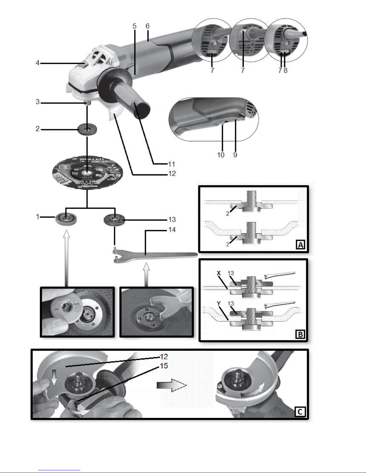
4. Overview
See page 2.
1 "Quick"clamping nut
2 Support flange
3 Spindle
4 Spindle locking button
5 Sliding on/off switch *
6 Handle
7 Electronic signal indicator *
8 Thumbwheel for selection of speed *
9 Trigger *
10 Switch-on lock
11 Side handle/ Side handle with vibration damping *
12 Safety cover
13 2-hole nut *
14 2-hole spanner *
15 Lever for safety guard attachment
* depending on equipment/not in scope of delivery
5. Commissioning
Before plugging in, check to see that the rated mains voltage and mains frequency, as stated
on the rating label, match with your power supply.
Always install an RCD/GFCI with a max. trip current of 30 mA upstream.
5.1 Attaching the side handle
Always work with the additional handle attached! (11) Attach the additional handle on the left or right
of the machine and secure.
5.2 Attach the safety guard
For safety reasons, always use the safety guard provided for the respective wheel! See
also chapter10. Accessories!
Safety guard for grinding
Designed for work with roughing wheels, flap sanding pads, diamond cut-off wheels.
See illustration on page 2.
- Push and hold the lever. (15) Place the safety guard in the position indicated. (12)
- Release the lever and turn the safety guard until the lever engages.
- Push the lever and turn the safety guard until the closed section is facing the
operator.
- Make sure that the guard is placed securely: The lever must engage and you should
not be able to turn the safety guard.
Use only accessories that are covered by at least 3.4 mm by the safety guard.

En ENGLISH
12
(Disassemble in reverse order.)
6. Attaching the grinding disc
Prior to any conversion work: Pull the mains plug from the socket. The machine must be
switched off and the spindle at a standstill.
For safety reasons, attach the cutting guard before performing cutting-off operations (see
chapter 10. Accessories).
6.1 Locking the spindle
- Press in the spindle locking button and turn the spindle by hand until the spindle locking button engages. (4)
6.2 Placing the grinding wheel in position
See illustration A on page 2.
- Fit the support flange on the spindle. (2) The flange should not turn on the spindle when properly attached.
- Place the grinding disc on the support flange. (2) The grinding disc must lay flat on the supporting
flange.
6.3 Securing/Releasing the “Quick-R” clamping nut (depending on features)
Securing the (1)”Quick-R” clamping nut:
Only attach the "Quick-R" clamping nut (1) to tools with "Walter Quick-R System". These
tools can be identified by the red spindle lock button (4) with " Quick-R " logo.
Do not use the “Quick-R” clamping nut if the accessory has a clamping shank thicker than 6.8 mm!
In this case, use the 2-hole nut (13) with 2- hole spanner (14).
- Lock the spindle (see chapter 6.1).
- Position the "Quick-R" clamping nut on the spindle so that the 2 lugs engage in the 2 grooves on the spindle.
(1) (3) See illustration on page 2.
- Tighten the "Quick “clamping nut by turning clockwise by hand.
- Turn the grinding wheel firmly clockwise to tighten the "Quick “clamping nut.
Releasing the clamping nut (1):
Only when the “Quick-R” clamping nut (1) is attached must the spindle be stopped using
the Quick-R spindle locking button (4).
- The machine continues to run after switching off.
- Press in the Quick-R spindle locking button just before the grinding disc stops. (4) The “Quick-R” clamping
nut (1) loosens itself by around half a turn and can be removed without additional effort or tools.
6.4 Securing/Releasing the 2-hole nut (depending on features)
Securing the 2-hole nut (13):
The 2 sides of the 2-hole nut are different. Screw the 2-hole nut onto the spindle as follows:
See illustration B on page 2.
X) For thin grinding discs:
The edge of the 2-hole nut (13) faces upwards so that the thin grinding disc can be attached securely.
Y) For thick grinding discs:
The edge of the 2-hole nut (13) faces downwards so that the 2-hole nut can be attached securely to the
spindle.
- Locking the spindle. Turn the 2-hole nut (13) clockwise using the 2-hole spanner (14) to secure.
Releasing the 2-hole nut:
- Lock the spindle (see chapter 6.1). Turn the 2-hole nut (13) anticlockwise using the 2-hole spanner (14) to
unscrew.
7. Use
7.1 Adjusting the speed (depending on features)
Set the recommended speed at the thumbwheel. (8) (small number = low speed; large number = high speed).
Cutting disc, roughing disc, cup wheel and diamond cutting disc: high speed
Brush: medium speed
Sanding plate: low to medium speed

En ENGLISH
13
Note: We recommend using our angle polisher for polishing work.
7.2 Switching On and Off
Always guide the machine with both hands.
Switch on first, and then guide the accessory towards the workpiece.
Avoid inadvertent starts: always switch the tool off when the plug is removed from the mains socket or if
there has been a power cut.
In continuous operation, the machine continues running if it is forced out of your hands. Therefore,
always hold the machine with both hands using the handles provided, stand securely and concentrate.
Avoid the machine swirling up or taking in dust and chips. After switching off the machine, only place it
down when the motor has come to a standstill.
Machines with slide switch:
Switching on: Push the sliding switch forward. (5) For continuous activation, now tilt downwards until it
engages.
Switching off: Press the rear end of the slide switch (5) and release it.
Machines with paddle switch (with non-locking function):
Switching on: Slide the switch-on lock (10) in the direction of the arrow and press the trigger (9).
Switching off: Release the trigger switch. (9)
Machines with the designation IRONMAN:
Torque activation (with dead man's switch)
Switching on: Slide the trigger switch (9) forwards and then push the trigger switch (9) upwards.
Switching off: Release the trigger switch (9).
Machines with the designation IRONMAN:
Continuous operation (depending on features)
Switching on: Switch the machine on as described above. Now slide the trigger switch (9) forwards again
and release in the front position to lock the trigger switch (9) (continuous operation).
Switching off: Push the trigger switch (9) upwards and release.

En ENGLISH
14
7.3 Working Directions
Grinding and sanding operations:
Press down the machine evenly on the surface and move back and forth so that the surface of the workpiece
does not become too hot. Rough grinding: position the machine at an angle of 30° - 40° for the best working
results.
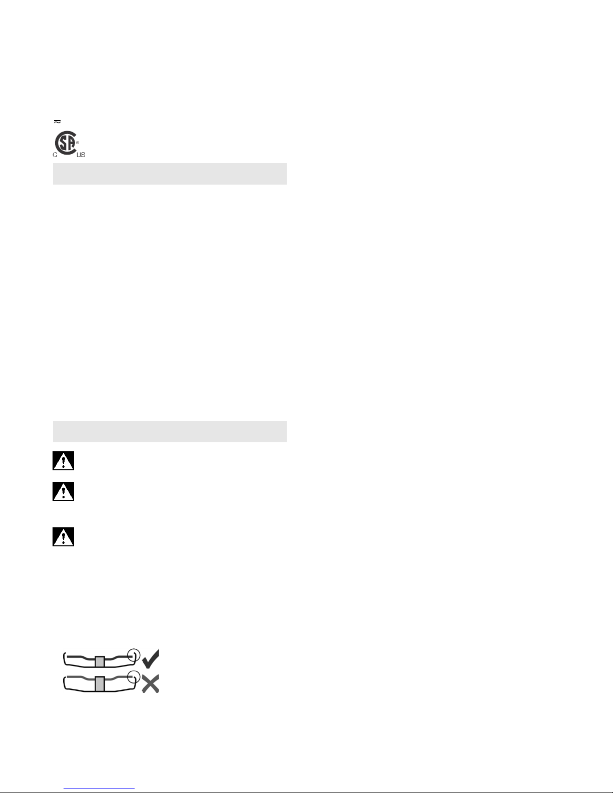
Abrasive cutting-off operations:
Always work against the run of the disc (see illustration). Otherwise there is the danger of the
machine kicking back from the cut out of control. Guide the machine evenly at a speed suitable
for the material being processed. Do not tilt, apply excessive force or sway from side to side.
Wire brushing:
Press down the machine evenly.
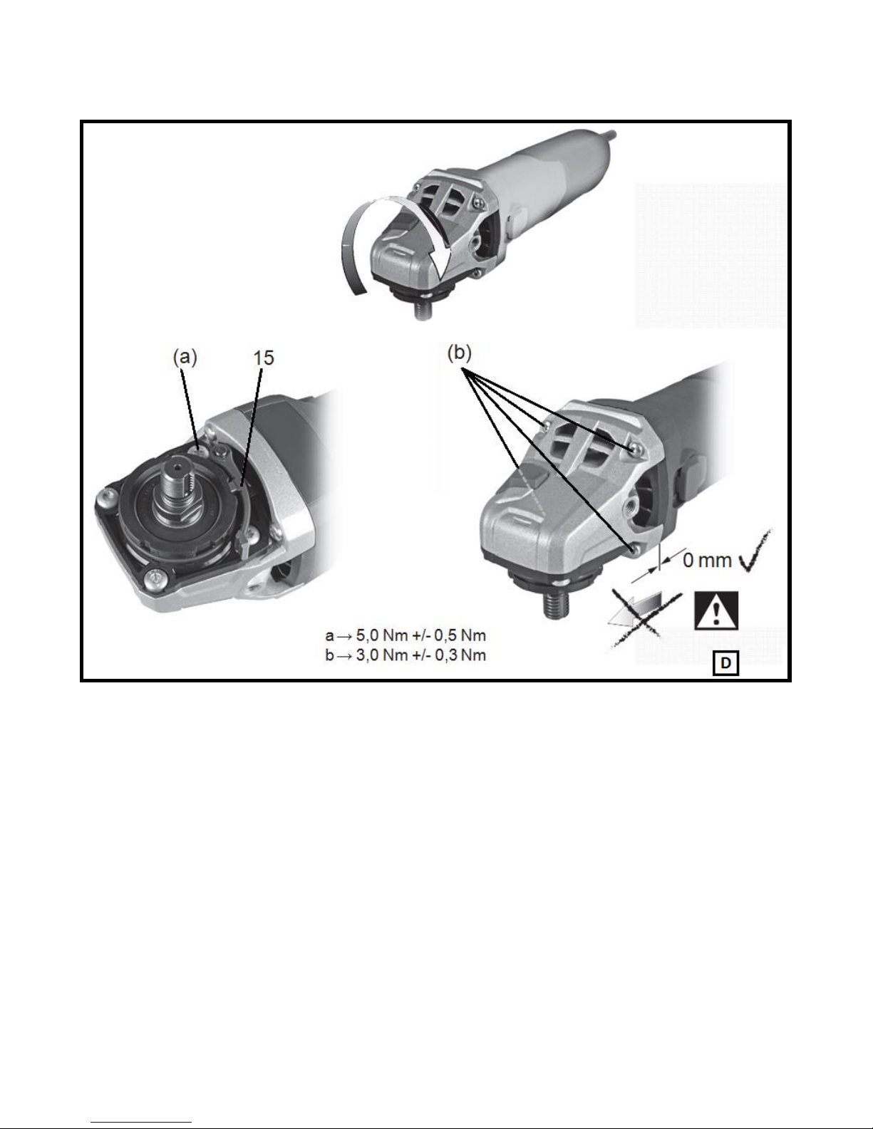
7.4 Rotate gear housing
See illustration D on page 3.
- Disconnect from the power supply.
- Unscrew the fastening screw (a) of the lever (15). Remove the screw, lever (with its sheet metal part) and put
aside.
- Unscrew the 4 gear housing screws (b). CAUTION! Do not remove the gear housing
!
- Turn the gear housing to the desired position without removing it.
- Screw in the 4 gear housing screws (b) in the available threads! Tightening torque=3.0Nm +/- 0.3Nm.
- Slide the spring that pushes the lever in position to the side and re-insert the lever (15) (with its sheet metal
part), and fix with the fastening screw (a). Tightening torque = 5.0 Nm +/- 0.5 Nm. Check the
lever for correct function: it has to be under spring tension.
8. Cleaning
It is possible that particles deposit inside the power tool during operation. This impairs the cooling of the power
tool. Conductive build-up can impair the protective insulation of the power tool and cause electrical hazards.
The power tool should be cleaned regularly, often and thoroughly through all front and rear air vents using a
vacuum cleaner. Prior to this operation, separate the power tool from the power source and wear protective
glasses and dust mask.
9. Troubleshooting
Machines with DIALSPEED and DYNAMAX electronics:
The electronic signal display lights up and the load speed decreases. (7) There is too much load
on the machine! Run the machine in idling until the electronics signal indicator switches off.
Machines with DIALSPEED, DYNAMAX electronics:
The electronic signal display (7) flashes and the machine doesn’t start. The restart protection is
active. If the mains plug is inserted with the machine switched on, or if the power supply is restored
following an interruption, the machine does not start up. Switch the machine off and on again.
9

En ENGLISH
15
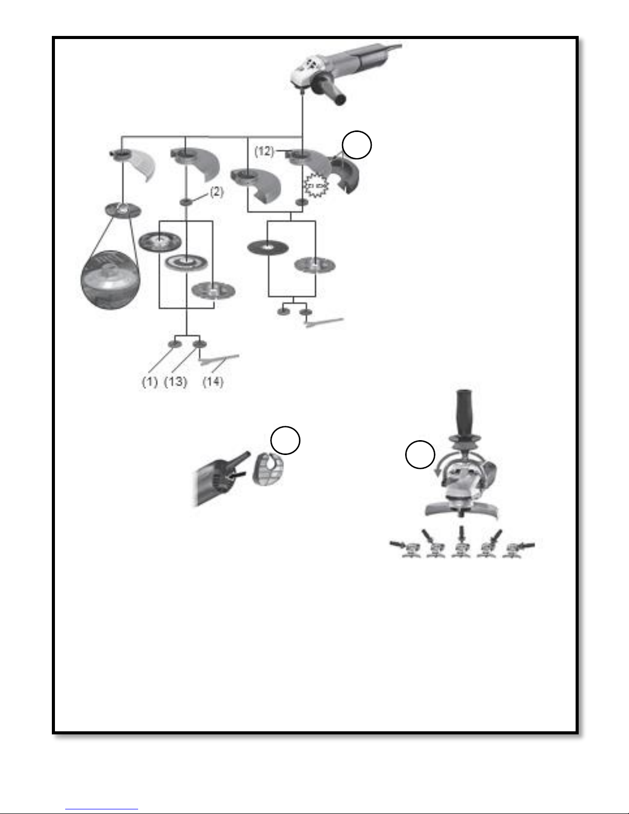
10. Accessories
Use only genuine Walter accessories. See page 5.
Use only accessories which fulfill the requirements and specifications listed in these operating instructions.
A Cutting guard clip / guard for cut-off grinding
Designed for work with cutting disc and diamond cutting discs. Once the cutting guard clip is fitted, the safety
guard becomes a cutting guard.
B Dust filter
The fine mesh filter prevents coarse particles from entering the motor housing. Remove regularly and clean.
C Multiple position bar for side handle
Permits numerous handle positions.
For a complete range of accessories, see www.walter.com or the accessories catalogue.
11. Repairs
Repairs to electrical tools must be carried out by qualified electricians ONLY! If the connection lead is
damaged, it must be replaced by a special connection lead. Contact your local Walter representative
if you have Walter power tools requiring repairs. For addresses see www.walter.com.
You can download a list of spare parts from www.walter.com.
12. Environmental Protection
The generated grinding dust may contain harmful substances. Dispose appropriately.
Observe national regulations on environmentally compatible disposal and on the recycling of disused
machines, packaging and accessories.
13. Technical Specifications
Explanatory notes on the specifications on page 4. Changes due to technological progress reserved.
Ø = max. diameter of the accessory
t
max,1
= max. permitted thickness of the clamping shank on accessory when using 2-hole nut (13)
t
max,2
= max. permitted thickness of clamping shank on accessory when using “Quick-R” clamping nut
t
max,3
= roughing disc/cutting disc:
max. permitted thickness of accessory
M = spindle thread
l = length of the grinding spindle
n* = no-load speed (maximum speed)
nV* = no-load speed (adjustable)
P
1
= rated input power
P
2
= power output
I
120 V
= Current at 120 V
m = weight without mains cable
* Machines with the designation DYNAMAX or DIALSPEED : Energy-rich, high-frequency interference can
cause fluctuations in speed. The fluctuations disappear, however, as soon as the interference fades away.
The technical specifications quoted are subject to tolerances (in compliance with the relevant valid standards).
Emission values
These values make it possible to assess the emissions from the power tool and to compare
different power tools. Depending on the operating conditions, the condition of the power tool or the
accessories, the actual load may be higher or lower.

En ENGLISH
16
For assessment purposes, please allow for breaks and periods when the load is lower. Based on the adjusted
estimates, arrange protective measures for the user e.g. organisational measures.
Vibration total value (vector sum of three directions) determined in accordance with EN 60745:
a
h, SG
= Vibration emission value
(surface grinding)
a
h, DS
= Vibration emission value
(sanding with sanding plate)
a
h, P
= Vibration emission value
(po
lishing)
K
h,SG/DS/P
= Uncertainty (vibration)
Wear ear protector
s!
WARRANTY POLICY
All WALTER power tools and accessories are inspected and tested before shipping and are warranted to be
free from any defect in material and faulty workmanship. Should any malfunction occur within (2) years from
the date of original purchase, return the complete tool prepaid, with proof of purchase, to the nearest
WALTER Factory or Authorized Service Center. If an examination shows that the malfunction was caused by
defective material or faulty workmanship, WALTER will repair (or at our option, replace) without charge. This
warranty does not apply when; normal maintenance is required, repairs or replacements have been made or
were attempted by anyone other than WALTER authorized service personnel, and does not cover any
damage caused by accidents, modifications, use of improper accessories, abuse or misuse, which also
includes overloading the tool beyond its rated capacity as well as its continued use after partial failure. No
other warranty, written or verbal, is authorized.
In no event shall WALTER be liable for any indirect, incidental or consequential damages from the sale of the
product. This disclaimer applies both during and after the term of this warranty.
This warranty gives you specific rights. The provisions contained in this warranty are not intended to limit,
modify, take away from, disclaim or exclude any warranties set forth in any provincial legislation. To the
extent required by law, the provisions in any provincial, or federal legislation with respect to warranties take
precedence over the provisions in this warranty.

Fr FRANÇAIS
17
Mode d'emploi
1. Utilisation conforme à la destination
Les meuleuses d'angle sont destinées avec les accessoires Walter d'origine au meulage, au ponçage, aux
travaux à la brosse métallique et au tronçonnage de pièces de métal, de béton, de pierre et d'autres
matériaux similaires sans utiliser d'eau.
Le QUICK-STEP FINISHER 6” conviennent également aux opérations de finition. Pour les opérations de
finition exigeantes en fonctionnement continu, nous recommandons d’utiliser notre meuleuse à queue de
rat QUICK-STEP BIG-BUFF III.
Les machines avec la mention DIALSPEED conviennent particulièrement aux travaux avec des brosses
métalliques en raison de leur gradateur permettant le réglage de la vitesse.
L'utilisateur sera entièrement responsable de tous dommages résultant d'une utilisation non conforme.
Il est impératif de respecter les consignes générales de protection contre les accidents ainsi que les
consignes de sécurité ci-jointes.
2. Consignes générales de sécurité
Pour des raisons de sécurité et afin de protéger l'outil électrique, respecter les passages de texte
marqués de ce symbole !
AVERTISSEMENT – Lire la notice d'utilisation afin d'éviter tout risque de blessure.
Remettre l'outil électrique à une personne seulement s’il est accompagné du présent manuel.
Avertissements de sécurité généraux pour l'outil
AVERTISSEMENT – Lire tous les avertissements de sécurité et toutes les instructions. Ne pas
suivre les avertissements et instructions peut donner lieu à un choc électrique, un incendie et/ou une
blessure sérieuse.
Conserver tous les avertissements et toutes les instructions pour pouvoir s'y reporter
ultérieurement! Le terme «outil» dans les avertissements fait référence à votre outil électrique alimenté par
le secteur (avec cordon d'alimentation) ou votre outil fonctionnant sur batterie (sans cordon d'alimentation).
2.1 Sécurité de la zone de travail
a) Conserver la zone de travail propre et bien éclairée. Les zones en désordre ou sombres sont propices
aux accidents.
b) Ne pas faire fonctionner les outils électriques en atmosphère explosive, par exemple en présence
de liquides inflammables, de gaz ou de poussières. Les outils électriques produisent des étincelles qui
peuvent enflammer les poussières ou les fumées.
c) Maintenir les enfants et les personnes présentes à l'écart pendant l'utilisation de l'outil. Les
distractions peuvent vous faire perdre le contrôle de l'outil.
2.2 Sécurité électrique
a) Il faut que les fiches de l'outil électrique soient adaptées au socle. Ne jamais modifier la fiche de
quelque façon que ce soit. Ne pas utiliser d'adaptateurs avec des outils à branchement de terre.
Des fiches non modifiées et des socles adaptés réduiront le risque de choc électrique.
b) Eviter tout contact du corps avec des surfaces reliées à la terre telles que les tuyaux, les
radiateurs, les cuisinières et les réfrigérateurs. Il existe un risque accru de choc électrique si votre corps
est relié à la terre.
c) Ne pas exposer les outils à la pluie ou à des conditions humides. La pénétration d'eau à l'intérieur
d'un outil augmentera le risque de choc électrique.
d) Ne pas maltraiter le cordon. Ne jamais utiliser le cordon pour porter, tirer ou débrancher l'outil.
Maintenir le cordon à l'écart de la chaleur, du lubrifiant, des arêtes ou des parties en mouvement.
Des cordons endommagés ou emmêlés augmentent le risque de choc électrique.
e) Lorsqu'on utilise un outil à l'extérieur, utiliser un prolongateur adapté à l'utilisation extérieure.
L'utilisation d'un cordon adapté à l'utilisation extérieure réduit le risque de choc électrique.

Fr FRANÇAIS
18
f) Si l'usage d'un outil dans un emplacement humide est inévitable, utiliser une alimentation protégée
par un dispositif à courant différentiel résiduel (RCD). L'usage d'un RCD réduit le risque de choc
électrique.
2.3 Sécurité des personnes
a) Rester vigilant, regarder ce que vous êtes en train de faire et faire preuve de bon sens dans votre
utilisation de l'outil. Ne pas utiliser un outil lorsque vous êtes fatigué ou sous l'emprise de drogues,
d'alcool ou de médicaments. Un moment d'inattention en cours d'utilisation d'un outil peut entraîner des
blessures graves des personnes.
b) Utiliser un équipement de sécurité. Toujours porter une protection pour les yeux. Les équipements
de sécurité tels que les masques contre les poussières, les chaussures de sécurité antidérapantes, les
casques ou les protections acoustiques utilisés pour les conditions appropriées réduiront les blessures de
personnes.
c) Eviter tout démarrage involontaire. S'assurer que l'interrupteur est en position arrêt avant de
brancher l'outil au secteur et/ou au bloc de batteries, de le ramasser ou de le porter. Porter les outils
en ayant le doigt sur l'interrupteur ou brancher des outils dont l'interrupteur est en position marche est
source d'accidents.
d) Retirer toute clé de réglage avant de mettre l'outil en marche. Une clé laissée fixée sur une partie
tournante de l'outil peut donner lieu à des blessures de personnes.
e) Ne pas se précipiter. Garder une position et un équilibre adaptés à tout moment. Cela permet un
meilleur contrôle de l'outil dans des situations inattendues.
f) S'habiller de manière adaptée. Ne pas porter de vêtements amples ou de bijoux. Garder les
cheveux, les vêtements et les gants à distance des parties en mouvement. Des vêtements amples,
des bijoux ou les cheveux longs peuvent être pris dans des parties en mouvement.
g) Si des dispositifs sont fournis pour le raccordement d'équipements pour l'extraction et la
récupération des poussières, s'assurer qu'ils sont connectés et correctement utilisés. Utiliser des
collecteurs de poussière peut réduire les risques dus aux poussières.
2.4 Utilisation et entretien de l'outil
a) Ne pas forcer l'outil. Utiliser l'outil adapté à votre application. L'outil adapté réalisera mieux le travail
et de manière plus sûre au régime pour lequel il a été construit.
b) Ne pas utiliser l'outil si l'interrupteur ne permet pas de passer de l'état de marche à arrêt et vice
versa. Tout outil qui ne peut pas être commandé par l'interrupteur est dangereux et il faut le réparer.
c) Débrancher la fiche de la source d'alimentation en courant et/ou le bloc de batteries de l'outil
avant tout réglage, changement d'accessoires ou avant de ranger l'outil. De telles mesures de sécurité
préventives réduisent le risque de démarrage accidentel de l'outil.
d) Conserver les outils à l'arrêt hors de la portée des enfants et ne pas permettre à des personnes
ne connaissant pas l'outil ou les présentes instructions de le faire fonctionner. Les outils sont
dangereux entre les mains d'utilisateurs novices.
e) Observer la maintenance de l'outil. Vérifier qu'il n'y a pas de mauvais alignement ou de blocage
des parties mobiles, des pièces cassées ou toute autre condition pouvant affecter le
fonctionnement de l'outil. En cas de dommages, faire réparer l'outil avant de l'utiliser. De nombreux
accidents sont dus à des outils mal entretenus.
f) Garder affûtés et propres les outils permettant de couper. Des outils destinés à couper correctement
entretenus avec des pièces coupantes
tranchantes
sont moins susceptibles de bloquer et sont plus faciles à
contrôler.
g) Utiliser l'outil, les accessoires et les lames etc., conformément à ces instructions, en tenant
compte des conditions de travail et du travail à réaliser. L'utilisation de l'outil pour des opérations
différentes de celles prévues pourrait donner lieu à des situations dangereuses.
2.5 Maintenance et entretien
a) Faire entretenir l'outil par un réparateur qualifié utilisant uniquement des pièces de rechange
identiques. Cela assurera que la sécurité de l'outil est maintenue.
3. Consignes de sécurité particulières
3.1 Avertissements de sécurité communs pour les opérations de meulage, de ponçage, de
polissage (modèles 6255 et 6275 seulement), de brossage métallique ou de tronçonnage par meule
abrasive :
a) Cet outil électrique est destiné à fonctionner comme meuleuse, ponceuse, br
oss
e métallique ou
outil à tronçonner. Lire toutes les mises en garde de
sécurité,
les instructions, les illustrations et les

Fr FRANÇAIS
19
spécifications fournies avec cet outil électrique. Le fait de ne pas suivre toutes les instructions données
ci-dessous peut avoir pour conséquence un choc électrique, un incendie et/ou une blessure grave.Les
modèles possédant les options DIALSPEED (QUICK-STEP FINISHER 6” et QUICK-STEP BIG-BUFF III)
peuvent également être utilisés comme polisseuse.
b) Les opérations de polissage ne sont pas recommandées avec cet outil électrique. Toute opération
non conforme à celles pour lesquelles l’outil électrique est conçu peut provoquer un danger et causer un
accident corporel. (Non applicable pour aux modèles avec DIALSPEED)
c) Ne pas utiliser d’accessoires non conçus spécifiquement et recommandés par le fabricant
d’outils. Le simple fait que l’accessoire puisse être fixé à l'outil électrique ne garantit pas un fonctionnement
en toute sécurité.
d) La vitesse assignée de l’accessoire doit être au moins égale à la vitesse maximale indiquée sur
l’outil électrique. Les accessoires fonctionnant plus vite que leur vitesse assignée peuvent se rompre et
voler en éclat.
e) Le diamètre extérieur et l’épaisseur de l'accessoire doivent se situer dans le cadre des
caractéristiques de capacité de l'outil électrique. Les accessoires dimensionnés de façon incorrecte ne
peuvent pas être protégés ou commandés de manière appropriée.
f) La taille des meules, flasques, plateaux à meuler ou tout autre accessoire doit s’adapter
correctement à l’arbre de l’outil électrique. Les accessoires avec alésages centraux ne correspondant
pas aux éléments de montage de l’outil électrique seront en déséquilibre, vibreront excessivement et
pourront provoquer une perte de contrôle.
g) Ne pas utiliser d’accessoire endommagé. Avant chaque utilisation examiner les accessoires
comme les meules abrasives pour détecter la présence éventuelle d'ébréchures et de fissures, les
patins d’appui pour détecter des traces éventuelles de fissures, de déchirure ou d’usure excessive,
ainsi que les brosses métalliques pour détecter des fils desserrés ou fissurés. Si l’outil électrique
ou l’accessoire a subi une chute, examiner les dommages éventuels ou installer un accessoire non
endommagé. Après examen et installation d’un accessoire, placer toutes les personnes présentes
à distance du plan de l’accessoire rotatif et faire marcher l’outil électrique à vitesse maximale à vide
pendant une minute. Les accessoires endommagés seront normalement détruits pendant cette période
d’essai.
h) Porter un équipement de protection individuelle. En fonction de l’application, utiliser un écran
facial, des lunettes de sécurité ou des verres de sécurité. Le cas échéant, utiliser un masque
antipoussières, des protections auditives, des gants et un tablier capables d’arrêter les petits
fragments abrasifs ou des pièces à usiner. La protection oculaire doit être capable d’arrêter les débris
volants produits par les diverses opérations. Le masque antipoussières ou le respirateur doit être capable de
filtrer les particules produites par les travaux. L’exposition prolongée aux bruits de forte intensité peut
provoquer une perte de l’audition.
i) Maintenir les personnes présentes à une distance de sécurité par rapport à la zone de travail.
Toute personne entrant dans la zone de travail doit porter un équipement de protection individuelle.
Des fragments de pièce à usiner ou d’un accessoire cassé peuvent être projetés et provoquer des blessures
en dehors de la zone immédiate d’opération.
j) Tenir l’outil uniquement par les surfaces de préhension isolantes, pendant les opérat
ions
au cours
desquelles l’accessoire coupant peut être en contact avec des conducteurs cachés ou avec son
propre câble. Le contact avec un conducteur
électrique
sous
tension
peut également mettre les
parties
métalliques
de l'outil sous tension et provoquer un choc électrique.
k) Placer le câble éloigné de l’accessoire de rotation. En cas de perte de contrôle de l'appareil, le câble
peut être coupé ou accroché et la main ou le bras de
l'utilisateur
peuvent être tirés dans l’accessoire de
rotation.
l) Ne jamais reposer l’outil électrique avant immobilisation complète de l’accessoire. L’accessoire de
rotation peut agripper la surface et arracher l’outil électrique hors de contrôle.
m) Ne pas faire fonctionner l’outil électrique en le portant sur le côté. Un contact accidentel avec
l’accessoire de rotation pourrait accrocher les vêtements et attirer l’accessoire sur l'utilisateur.
n) Nettoyer régulièrement les orifices d’aération de l’outil électrique. Le ventilateur du moteur attire la
poussière à l’intérieur du boîtier et une accumulation excessive de poudre de métal peut provoquer des
dangers électriques. o) Ne pas faire fonctionner l’outil électrique à proximité de matériaux
inflammables. Des étincelles pourraient enflammer ces matériaux.
p) Ne pas utiliser d’accessoires qui nécessitent des réfrigérants fluides. L’utilisation d’eau ou d’autres
réfrigérants fluides peut aboutir à une électrocution ou un choc électrique.

Fr FRANÇAIS
20
3.2 Rebonds et mises en garde correspondantes
Le rebond est une réaction soudaine au pincement ou à l’accrochage d’une meule, d’un patin d’appui, d’une
brosse ou de tout autre accessoire. L'outil électrique incontrôlable accélère alors dans le sens opposé de
l'accessoire au point d'accrochage. Par exemple, si une meule est accrochée ou pincée par la pièce à
usiner, le bord de la meule qui entre dans le point de pincement peut creuser la surface du matériau,
provoquant des sauts ou l’expulsion de la meule. La meule peut se déplacer en direction de l’utilisateur ou
encore en s’en éloignant, selon le sens du mouvement de la meule au point de pincement. Les meules
peuvent également se rompre dans ces conditions. Le rebond résulte d’un mauvais usage de l’outil et/ ou
de procédures ou de conditions de fonctionnement incorrectes et peut être évité en prenant les précautions
appropriées spécifiées ci- dessous.
a) Maintenir fermement l’outil électrique et placer le corps et les bras de manière à pouvoir résister
aux forces de rebond. Toujours utiliser une poignée auxiliaire, le cas échéant, pour une maîtrise
maximale du rebond ou de la réaction de couple au cours du démarrage. L’utilisateur peut maîtriser
les couples de réaction ou les forces de rebond, si les précautions qui s’imposent sont prises.
b) Ne jamais placer la main à proximité de l’accessoire en rotation. L’accessoire peut effectuer un
rebond sur la main.
c) Ne pas se placer dans la zone où l’outil électrique se déplacera en cas de rebond. Le rebond
pousse l’outil dans le sens opposé au mouvement de la meule au point d’accrochage.
d) Apporter un soin particulier lors de travaux dans les coins, les arêtes vives etc. Eviter les
rebondissements et les accrochages de l’accessoire. Les coins, les arêtes vives ou les rebondissements
ont tendance à accrocher l’accessoire en rotation et à provoquer une perte de contrôle ou un rebond.
e) Ne pas fixer de lame de scie à chaîne ou de scie dentée. De telles lames provoquent des rebonds
fréquents et des pertes de contrôle.
3.3 Mises en garde de sécurité spécifique aux opérations de meulage et de tronçonnage abrasif :
a) Utiliser uniquement des types de meules recommandés pour l'outil électrique et le protecteur
spécifique conçu pour la meule choisie. Les meules pour lesquelles l’outil électrique n’a pas été conçu
ne peuvent pas être protégées de façon satisfaisante et sont dangereuses.
b) Les meules coudées doivent être fixées de façon à ce que la surface de rectification se trouve
sous le bord du capot de protection. Une meule incorrectement fixée, qui dépasse du bord du capot de
protection, ne peut pas être protégée de façon adaptée.
c) Le garde de protection doit être solidement fixé à l’outil électrique et réglé à des fins de sécurité
maximale, de sorte que l’opérateur soit exposé le moins possible à la meule. Le garde de protection
contribue à protéger l'utilisateur contre les fragments, le contact accidentel avec la meule, ainsi que contre
les étincelles, qui pourraient enflammer les vêtements.
d) Les meules doivent être utilisées uniquement pour les applications recommandées.
Par exemple : ne pas meuler avec le côté de la meule à tronçonner. Les meules à tronçonner abrasives
sont destinées au meulage périphérique, l’application de forces latérales à ces meules peut les briser en
éclats. Tout effort latéral sur ces meules peut les briser.
e) Toujours utiliser des flasques de serrage non endommagés qui sont de taille et de forme correctes
pour la meule choisie. Des flasques de meule appropriés supportent la meule réduisant ainsi la possibilité
de rupture de la meule. Les flasques pour les meules à tronçonner peuvent être différents des autres
flasques de meule.
f) Ne pas utiliser de meules usées d’outils électriques plus grands. La meule destinée à un outil
électrique plus grand n’est pas appropriée pour la vitesse plus élevée d’un outil plus petit et elle peut éclater.
3.4 Mises en garde de sécurité additionnelles spécifiques aux opérations de tronçonnage abrasif
:
a) Ne pas «coincer» la meule à tronçonner ou ne pas appliquer une pression excessive. Ne pas
tenter d’exécuter une profondeur de coupe excessive. Une contrainte excessive de la meule augmente
la charge et la probabilité de torsion ou de blocage de la meule dans la coupe et la possibilité de rebond ou
de rupture de la meule.
b) Ne pas se placer dans l’alignement de la meule en rotation ni derrière celle-ci. Lorsque la meule,
au point de fonctionnement, s’éloigne du corps, le rebond éventuel peut propulser la meule en rotation et
l’outil électrique directement sur l'utilisateur.
c) Lorsque la meule se bloque ou lorsque la coupe est interrompue pour une raison quelconque,
mettre l’outil électrique hors tension et tenir l’outil électrique immobile jusqu’à ce que la meule soit
à l’arrêt complet. Ne jamais tenter d’enlever la meule à tronçonner de la coupe tandis que la meule
est en mouvement sinon le rebond peut se produire. Rechercher et prendre des mesures correctives
afin d’empêcher que la meule ne se coince.

Fr FRANÇAIS
21
d) Ne pas reprendre l’opération de coupe dans la pièce à usiner. Laisser la meule atteindre sa pleine
vitesse et rentrer avec précaution dans le tronçon. La meule peut se coincer, venir chevaucher la pièce
à usiner ou effectuer un rebond si l’on fait redémarrer l’outil électrique dans la pièce à usiner.
e) Prévoir un support de panneaux ou de toute pièce à usiner surdimensionnée pour réduire le risque
de pincement et de rebond de la meule. Les grandes pièces à usiner ont tendance à fléchir sous leur
propre poids. Les supports doivent être placés sous la pièce à usiner près de la ligne de coupe et près du
bord de la pièce des deux côtés de la meule.
f) Être particulièrement prudent lors d'une « coupe en retrait » dans des parois e
xistantes
ou dans
d’autres zones sans visibilité. La meule de coupe peut sectionner des tuyaux de gaz ou d’eau, des
câblages électriques ou des objets, ce qui peut entraîner des rebonds.
3.5 Mises en garde de sécurité spécifiques aux opérations de ponçage :
a) Ne pas utiliser de papier abrasif trop surdimensionné pour les disques de ponçage. Suivre les
recommandations des fabricants lors du choix du papier abrasif. Un papier abrasif plus grand
s’étendant au-delà du patin de ponçage présente un danger de lacération et peut provoquer un accrochage,
une déchirure du disque ou un rebond.
3.6 Uniquement pour les modèles MINI-PLUS (6255) et QUICK-STEP FINISHER (6275) 6” : Mises en
garde de sécurité spécifiques aux opérations de polissage :
Ne laisser aucune pièce détachée du bonnet de polissage, particulièrement les cordons d'attache.
Ranger ou couper les cordons d'attache. Les cordons d'attache lâches, entraînés dans une rotation
peuvent attraper les doigts ou se coincer dans une pièce à usiner.
3.7 Mises en garde de sécurité spécifiques aux opérations de brossage métallique :
a) Garder à l’esprit que des brins métalliques sont rejetés par la brosse même au cours d’une
opération ordinaire. Ne pas soumettre à une trop grande contrainte les fils métalliques en
appliquant une charge excessive à la brosse. Les fils métalliques peuvent aisément pénétrer dans des
vêtements légers et/ou la peau.
b) Si l’utilisation d’un protecteur est recommandée pour le brossage métallique, s’assurer que ce
dernier puisse fonctionner adéquatement sans nuire à la rotation de l’outil installé. L’outil, ex : la
brosse métallique peut se dilater en diamètre en raison de la charge de travail et des forces centrifuges.
3. 8 Autres consignes de sécurité : AVERTISSEMENT – Portez toujours des lunettes de protection.
Utiliser exclusivement des outils accessoires, qui sont au minimum en retrait de 3,4 mm par rapport
au garde de protection. Utiliser des intercalaires souples s'ils ont été fournis avec
l'accessoire de meulage et que leur utilisation s'impose. Respectez les indications de
l'outil ou du fabrication d'accessoires ! Protéger les disques des graisses et des coups !
Les meules doivent être conservées et manipulées avec soin, conformément aux
instructions du fabricant.
Ne jamais utiliser de meule à tronçonner pour les travaux de dégr ossissage ! Ne pas appliquer de pression
latérale sur les meules à tronçonner.
La pièce à usiner doit être fermement fixée de sorte à ne pas glisser, par exemple à l'aide de dispositifs de
serrage. Les pièces à usiner de grande taille doivent être suffisamment soutenues.
Si les outils de travail sont utilisés avec un insert fileté, l'extrémité de la broche ne doit pas toucher le fond
perforé de l'outil de meulage. S'assurer que le filetage de l'accessoire soit suffisamment long pour accueillir
la broche dans sa longueur. Le filetage de l'accessoire doit s'adapter au filetage de la broche. Voir la
longueur et le filetage de l’arbre au chapitre 13. Caractéristiques techniques.
Il est recommandé d'utiliser un système d'aspiration en poste fixe. Montez toujours un interrupteur de
protection contre les courants de court-circuit (RCD) avec un courant de déclenchement max. de
30 mA en amont. Lorsque la ponceuse d'angle est arrêtée par son interrupteur de protection FI, elle
doit être vérifiée et nettoyée. Voir chapitre 8. Nettoyage.
Ne jamais utiliser d'élément endommagé, présentant des faux-ronds ou vibrations.
Éviter les dommages sur les conduites de gaz ou d'eau, les câbles électriques et les murs porteurs
(statiques).
Débrancher le cordon d'alimentation de la prise de courant avant toute opération de réglage, de
changement d'outil de travail ou de maintenance.
Débrayage de sécurité Walter. En cas de déclenchement du débrayage de sécurité, arrêtez immédiatement
la machine !
Une poignée supplémentaire endommagée ou craquelée doit être remplacée. Ne pas utiliser la machine si
la poignée supplémentaire est défectueuse.

Fr FRANÇAIS
22
Un garde de protection endommagé ou craquelé doit être remplacé. Ne pas utiliser la machine si le garde
de protection est défectueux.
Les pièces de petite taille doivent être serrées, par ex. en les serrant dans un étau.
Réduction de la pollution due aux poussières :
Les particules émises lors du travail avec cette machine peuvent contenir des substances pouvant
entraîner des cancer, des réactions allergiques, des affections des voies respiratoires, des
malformations congénitales ou d'autres lésions du système reproducteur. Parmi ces substances on trouve
: Le plomb (dans les enduits contenant du plomb), la poussière minérale (dans les briques, le béton, etc.),
les additifs pour le traitement du bois (chromate, produits de protection du bois), quelques variétés de bois
(comme la poussière de chêne et de hêtre), les métaux, l'amiante.
Le risque dépend de la durée et de la proximité d'exposition de l'utilisateur.
Il est souhaitable que le corps n'absorbe pas ces
particules.
Afin de réduire la pollution due à ces substances : Veillez à une bonne aération du lieu de travail et
portez un équipement de protection adapté comme par exemple des masques antipoussières capables de
filtre les particules microscopiques.
Respectez les directives applicables au matériau, au personnel, à l'application et au lieu d'utilisation (par
exemple directives en matière de protection au travail, élimination des déchets).
Collectez les particules émises sur le lieu d'émission et évitez les dépôts dans l'environnement.
Utilisez des accessoires adaptés pour les travaux spécifiques (voir chapitre 10.). Cela permet de réduire
l'émission incontrôlée de particules dans l'environnement.
Utilisez un système d'aspiration des poussières adapté.
Réduisez la pollution due aux poussières en :
- évitant d'orienter les particules sortantes et l'air d'échappement de la machine vers vous ou vers des
personnes se trouvant à proximité ou vers des dépôts de poussière,
- utilisant un système d'aspiration et/ou un purificateur d'air,
- aérant convenablement le lieu de travail et en
l'aspirant pour le maintenir propre. Balayer ou souffler les poussières les font tourbillonner.
- Aspirez ou lavez les vêtements de protection. Ne
pas les souffler, les battre ni les brosser.
Symboles sur l'outil:
.......... Construction de classe II
V
............. volts
A
............. ampères
Hz
........... hertz
W ............ watts
Ø............. diamètre max. de l'outil de travail
.../min......
révolutions par minute
rpm ......... révolutions par minute
~ ............. courant alternatif
............ courant alternatif / courant continu
n ............. vitesse à vide
Les mentions "C" et "US" ajoutées au label CSA signifient qu'il s'agit d'un produit conforme aux normes
CSA et ANSI/UL, applicables pour un emploi du produit respective- ment au Canada et aux Etats-Unis.
4. Vue d'ensemble
Voir page 2
1 Écrou de serrage Quick-R *
2 Flasque d'appui
3 Broche
4 Bouton de blocage de la broche
5 Interrupteur coulissant de marche/arrêt *
6 Poignée
7 Témoin électronique *
8 Molette de réglage de la vitesse *
9 Gâchette *
10 Sécurité antidémarrage *

Fr FRANÇAIS
23
11 Poignée supplémentaire / poignée supplémentaire avec amortissement des vibrations *
12 Couvercle de protection
13 Écrou à deux trous frontaux *
14 Clé à ergots *
15 Levier de fixation du garde de protection
* suivant version/non compris dans la fourniture
5. Mise en service
Avant la mise en service, comparer si la tension secteur et la fréquence secteur indiquées sur la plaque
signalétique correspondent aux caractéristiques du réseau de courant.
Montez toujours un interrupteur de protection contre les courants de court-circuit (RCD/GFCI) avec un
courant de déclenchement max. de 30 mA en amont.
5.1 Placement de la poignée supplémentaire
Travaillez toujours avec une poignée supplémentaire appropriée (11) ! Visser la poignée
supplémentaire sur le côté gauche ou droit de la machine.
5.2 Fixation du garde de protection
Pour des raisons de sécurité, utilisez uniquement exclusivement le garde de protection prévu pour la meule
respective ! Voir également chapitre 10. "Accessoires" !
Garde de protection pour le meulage Conçu pour les travaux avec des disques à dégrossir, meules à
lamelles, meules de tronçonnage diamant.
Voir page 2, illustration C.
- Appuyez sur le levier (15) et maintenez-le abaissé. Placez le garde de protection (12) dans la position
indiquée.
- Relâcher le levier et orienter le garde de protection jusqu'à ce que le levier s'enclenche.
- Appuyer sur le levier et orienter le garde de protection de sorte que la zone fermée soit tournée vers
l'utilisateur.
- Vérifier la fixation : le levier doit être encliqueté et le garde de protection ne doit pas
changer de position.
Utiliser exclusivement des outils accessoires, qui sont au minimum en retrait de
3,4 mm par rapport au garde de protection. (Démontage dans l'ordre inverse.)
6. Placement de la meule
Avant tout changement d'équipement : Débrancher la fiche secteur de la prise de courant. La machine doit
être débranchée et la broche immobile.
Dans le cadre de travaux avec des meules à tronçonner, utiliser le garde de protection de meulage pour
des raisons de sécurité (voir chapitre 10. Accessoires).
6.1 Verrouillage de l’arbre
- Enfoncez le bouton de blocage de l’arbre d’entraînement (4) et (3) tournez la broche à la main jusqu'à
ce que le bouton de blocage entre dans un orifice prévu à cet effet.
6.2 Placement de la meule
Voir page 2, illustration A.
- Placer le flasque d'appui arrière (2) sur l’arbre. Il est correctement placé s'il est impossible de le
déplacer.
- Placer la meule sur le flasque d'appui arrière(2).
La meule doit être placée de manière équilibrée sur le flasque d'appui arrière.
6.3 Fixation/détachement de l'écrou de serrage Quick-R (suivant la version) Fixez l'écrou de
serrage Quick-R (1): uniquement fixer l'écrou de serrage Quick-R (1) sur des machines avec le système
Quick-R de Walter. Ces machines se distinguent par le bouton de blocage de l’arbre (4) avec l'inscription "
Quick-R".
Si l'outil de travail situé dans la zone de serrage est d'une épaisseur supérieure à 6,8mm, l'écrou de serrage
Quick-R ne doit pas être utilisé! Dans ce cas, utiliser l'écrou à deux trous frontaux (13) avec la clé à ergots
(14).
- Blocage de la broche (voir chapitre 6.1).
- Placez l'écrou de serrage Quick-R (1) sur la broche (3) de sorte que les 2 bords d'attaque s'insèrent dans
les 2 rainures de la broche. Voir illustration à la page 2.

Fr FRANÇAIS
24
- Retirez fermement l'écrou de serrage Quick-R à la main dans le sens horaire.
- En tournant fortement la meule dans le sens horaire, tirer sur l'écrou de serrage Quick-R.
Desserrer l'écrou de serrage Quick-R (1):
La broche peut seulement être arrêtée avec le bouton de blocage de la broche (1) lorsque
l'écrou de serrage Quick-R est installé (4) !
- Après sa mise hors tension, la machine continue de tourner.
- Peu avant l'immobilisation de la meule, appuyez
sur le bouton rouge Quick-R de blocage de la broche (4). L'écrou de serrage Quick-R (1) se
desserre automatiquement d'un demi-tour et peut être dévisser facilement ou sans outil. 6.4
Fixation/desserrage de l'écrou à deux trous frontaux (suivant la version)
Fixez l'écrou à deux trous frontaux
(13):
Les 2 côtés de l'écrou à deux trous frontaux sont différents. Visser l'écrou à deux trous frontaux sur l’arbre
tel que démontré à la page 2, illustration B.
- X) Pour les meules fines :
L'épaulement de l'écrou à deux trous frontaux (13) est orienté vers le haut, afin que la meule fine puisse être
serrée de façon sûre.
Y) Pour les meules épaisses :
L'épaulement de l'écrou à deux trous frontaux (13) est orienté vers le bas, afin que l'écrou à deux trous
frontaux puisse être fixé de façon sûre sur la broche.
- Verrouiller la broche. Vissez fermement l'écrou à deux trous frontaux (13) à l'aide de la clé à ergots (14)
dans le sens horaire.
Desserrer l'écrou à deux trous frontaux :
- Blocage de la broche (voir chapitre 6.1). Dévissez l'écrou à deux trous frontaux (13) à l'aide de la clé à
ergots (14) dans le sens anti-horaire.
7. Utilisation
7.1 Réglage de la vitesse (suivant la version)
Réglez la vitesse recommandée sur la molette (8). (petit chiffre : vitesse faible ; grand chiffre = vitesse élevée)
Meule à tronçonner, à dégrossir, meule-boisseau, meule à tronçonner en diamant : vitesse élevée
Brosse : vitesse moyenne
Disque à sabler : vitesse faible à moyenne
Note : Pour toute opération de polissage, nous recommandons notre polisseuse QUICK-STEP FINISHER ou
QUICK-STEP BIG-BUFF III.
7.2 Marche/arrêt
Toujours guider la machine des deux mains.
Mettez la machine sous tension avant de positionner la machine sur la pièce à usiner.
Évitez les démarrages involontaires : l'outil doit toujours être arrêté lorsque l'on retire le connecteur
de la prise ou après une coupure de courant.
Lorsque l'outil est en position de marche continue, il continue de tourner s'il vous échappe des mains.
Afin d'éviter tout comportement inattendu de l'outil, le tenir avec les deux mains au niveau des
poignées, veiller à un bon équilibre et travailler de manière concentrée.
Évitez que la machine ne fasse tourbillonner ou n'aspire de la poussière et des débris.
Après l'avoir arrêtée, ne poser la machine qu'une fois que le moteur a cessé de tourner.
Outils à interrupteur coulissant
:
Mise en route : Glisser l'interrupteur coulissant (5) vers l'avant. Pour un fonctionnement en continu, le
basculer vers l'arrière jusqu'au cran.
Arrêt
:
appuyer sur l'arrière de l'interrupteur coulissant (5), puis relâcher.
Outils à interrupteur "Paddle" (avec fonction homme mort)

Fr FRANÇAIS
25
Mise en marche : Pousser le verrouillage d'interrupteur (10) dans le sens de la flèche et appuyer sur la
gâchette (9).
Arrêt : Relâcher la gâchette (9).
Machines avec une désignation IRONMAN:
déclenchement intermittent (avec fonction homme mort
Mise en marche : faire glisser la gâchette (9) vers l’avant et pousser ensuite la gâchette (9) vers le haut.
Arrêt : relâcher la gâchette (9).
Machines avec une désignation IRONMAN: déclenchement continu (suivant l’équipement)
Mise en marche : mettre la machine en marche tel que décrit ci-dessous. Pousser à nouveau la gâchette
(9) vers l’avant et le relâcher en position antérieure pour bloquer la gâchette (9) (déclenchement).
Arrêt : pousser la gâchette (9) vers le haut et la relâcher.
7.3 Consignes pour le travail
Meulage et ponçage au papier de verre : Exercer sur la machine une pression mesurée et effectuer des
allers-retours sur la surface, afin que la surface de la pièce à usiner ne devienne pas trop chaude.
Dégrossissage : pour obtenir un résultat acceptable, travailler à un angle d'application compris entre 30°et
40°.
Tronçonnage :
lors des travaux de tronçonnage, travaillez toujours en sens opposé (voir l'illustration).
Sinon, la machine risque de sortir de la ligne de coupe de façon incontrôlée. Toujours
travailler avec une avance mesurée, adaptée au matériau à usiner. Ne pas positionner la
machine de travers, ne pas l'appuyer ni l'osciller.
Travaux avec les brosses métalliques
Exercer une pression mesurée sur la machine.
7.4 Tourner le carter de réducteur Voir page 3, illustration D.
- Retirer la prise d’alimentation.
- Dévisser la vis de fixation (a) du levier (15). Retirer la vis, le levier (avec sa pièce en tôle) et les mettre
de côté.
- Dévisser les 4 vis du carter de réducteur (b).
ATTENTION ! Ne pas retirer le carter de réducteur !
- Tourner le carter de réducteur dans la position souhaitée sans le retirer.
- Visser les 4 vis du carter de réducteur (b) dans les pas de vis ! Couple de serrage = 3,0Nm +/- 0,3Nm.
- Pousser le ressort qui maintient le levier en position vers le côté et replacer le levier (15) (avec sa pièce
en tôle) et le fixer à l'aide de la vis de fixation (a). Couple de serrage = 5,0Nm +/- 0,5Nm. Vérifier le bon
fonctionnement du levier : il doit être sous tension.

Fr FRANÇAIS
26
8. Nettoyage
Lors du travail, des particules peuvent se déposer à l'intérieur de l'outil électrique. Cela entrave le
refroidissement de l'outil électrique. Les dépôts de particules conductrices peuvent endommager l'isolation
de protection de l'outil électrique et entraîner un risque d'électrocution.
Aspirez régulièrement, souvent et soigneusement l'outil électrique à travers toutes les fentes d'aération
avant et arrière. Débranchez au préalable l'outil électrique du courant et portez des lunettes de protection
et un masque anti-poussière.
9. Dépannage
Machines équipées des systèmes électroniques DIALSPEED et DYNAMAX :
Le témoin électronique (7) allume et la vitesse en charge diminue. La machine est en surcharge !
Laisser fonctionner la machine à vide jusqu'à ce que le témoin électronique s’éteigne.
Machines équipées des systèmes électroniques DIALSPEED:
Le témoin électronique (7) clignote et la machine ne fonctionne pas. La protection contre le
redémarrage s'est déclenchée. Si le cordon d'alimentation est branché alors que la machine est sur
« Marche », ou si l'alimentation revient après une coupure de courant, la machine ne démarre pas.
Éteindre la machine et la remettre en marche.
10. Accessoires
Utilisez uniquement les produits Walter. Voir la page 5.
Utiliser exclusivement des accessoires, qui sont conformes aux exigences et données caractéristiques
indiquées dans la présente notice d'utilisation.
A Clip de garde de protection de meule de tronçonnage / Garde de protection pour le tronçonnage
Conçu pour les travaux avec des meules de tronçonnage, meules de tronçonnage diamant. Avec le clip de
garde de protection de meule de tronçonnage fixé, le garde de protection devient un garde de protection de
meule de tronçonnage.
B Filtre anti-poussière
Ce filtre dense empêche les grosses particules de pénétrer dans le carter du moteur. Retirer et nettoyer
régulièrement.
C Arceau multiposition pour poignée supplémentaire
Permet de nombreuses positions de préhension.
Gamme d'accessoires complète, voir www.walter.com ou le catalogue d'accessoires.
11. Réparations
Les travaux de réparation sur les outils électriques ne peuvent être effectués que par
un spécialiste !
Si le câble de raccordement de l'appareil est endommagé, le remplacer par un câble spécial.
Pour toute réparation sur un outil Walter, contacter le représentant Walter. Voir les adresses sur
www.walter.com.
Les listes des pièces détachées peuvent être téléchargées sur www.walter.com.
12. Protection de l'environnement
La poussière émise lors du meulage peut contenir des
substances dangereuses : Éliminer
de manière
conforme. Suivre les règlementations nationales concernant l'élimination dans le respect de
l'environnement
et le recyclage des machines, emballages et accessoires.

Fr FRANÇAIS
27
13. Caractéristiques techniques
Commentaires sur les indications de la page 4. Sous réserve de modifications allant dans le sens du progrès
technique.
Ø = diamètre max. de l'outil de travail
t
max,1
= épaisseur max. admise de l'outil de travail dans la zone de serrage avec utilisation d'un écrou à
deux trous frontaux (13)
t
max,2
= épaisseur max. admissible de l'accessoire dans la zone de serrage avec utilisation d'un écrou de
serrage Quick-R (1)
t
max,3
= meule de dégrossissage/meule de tronçonnage : épaisseur max. admise de l'outil de travail
M = filet de la broche
l = longueur de la broche porte-meule
n* = vitesse à vide (vitesse max.)
nV* = vitesse à vide (réglable)
P
1
= puissance absorbée
P
2
= puissance débitée
I
120 V
= courant sous 120 V
m = poids sans câble d'alimentation
*Machines avec les fonctionnalités DIALSPEED : Les perturbations à fréquence et à énergie élevées
peuvent occasionner des variations de vitesse. Ces variations cessent dès la disparition des perturbations.
Les caractéristiques indiquées sont soumises à tolérance (selon les normes en vigueur correspondantes).
Valeurs d'émission
Ces valeurs permettent l'estimation des émissions de l'outil électrique et la comparaison entre
différents outils électriques. Selon les conditions d'utilisation, l'état de l'outil électrique ou les accessoires
utilisés, la sollicitation réelle peut varier plus ou moins. Pour l'estimation, tenir compte des pauses de travail
et des phases de sollicitation moindre. Définir des mesures de protection pour l'utilisateur sur la base des
valeurs estimatives adaptées en conséquence, p. ex. mesures organisationnelles.
Valeur totale de vibration (somme des vecteurs des trois directions) définie selon la norme EN 60745 : ah,
SG=valeur d'émission vibratoire (Meulage de surfaces)
a
h, DS
= valeur d'émission vibratoire (meulage avec un plateau de ponçage)
a
h, P
= valeur d'émission vibratoire
(polissage)
K
h,SG/DS/P
= incertitude (vibration)
Porter des proteceur auditifs en tout temps
!
POLITIQUE DE GARANTIE
Toutes les machines et accessoires WALTER sont vérifiés et inspectés avant chaque xpédition et sont garanties
exempts de toute défectuosité de matériel ou de fabrication. Si une machine fait défaut dans les deux ans suivant
l'achat initial, elle doit être retournée port payé avec preuve d'achat à un Centre de Service Autorisé WALTER. Si
une vérification révèle une défectuosité de matériel ou de fabrication, la réparation ou l'échange de la machine (selon
la décision de WALTER) sera effectué(e) sans frais.
Cette garantie ne s'applique pas si un entretien normal est requis ou si des réparations ont été tentées par d'autres
techniciens que ceux autorisés par WALTER. Cette garantie ne s’applique pas aux dommages causés par des
accidents, des modifications, l'utilisation d'accessoires inadéquats, l'usure normale, l'abus ou un mauvais usage
(incluant le fonctionnement sous une charge excédant la capacité nominale) ou l'utilisation après avoir endommagé
partiellement la machine. Aucune autre garantie, tant écrite que verbale, n'est autorisée. WALTER ne sera, en
aucun cas, tenu responsable pour tout dommage indirect, incident ou conséquent à la vente du produit. Ce
désistement s'applique durant et après l'échéance de cette garantie.
Cette garantie vous confère des droits spécifiques. Les conditions contenues dans cette garantie ne visent
pas à limiter, modifier, retirer, nier ou exclure toute garantie établie par les législations provinciales ou
fédérales. Dans la mesure prescrite, les dispositions de toute loi provinciale ou fédérale ont priorité sur les
conditions de la présente garantie.

Fr FRANÇAIS
28

Es ESPAÑOL
29
Instrucciones de manejo
1. Aplicación de acuerdo a la finalidad
Las amoladoras angulares, con los accesorios originales Walter, son aptas para el lijado, esmerilado con
papel de lija, trabajo con cepillo de alambre y tronzado de metal, hormigón, piedra y materiales similares
sin necesidad de utilizar agua. Los modelosDIALSPEED, QUICK-STEP FINISHER 6” son además aptos
para trabajos de pulido ligero. Para los trabajos de pulido más exigentes y para el uso continuado,
recomendamos nuestra pulidora angular. Las máquinas identificadas con DIALSPEED, tienen una
ruedecilla de ajuste para regular la velocidad, por ello son especialmente recomendables para trabajos con
cepillos de púas. Los posibles daños derivados de un uso inadecuado son responsabilidad exclusiva del
usuario. Se deberán respetar las normas sobre prevención de accidentes generalmente aceptadas y la
información sobre seguridad aquí incluida.
2. Instrucciones generales de seguridad
Para su propia protección y la de su
herramienta
eléctrica, observe las partes marcadas con este
símbolo.
ADVERTENCIA: Lea el manual de instrucciones para reducir el riesgo de accidentes.
Si entrega su herramienta eléctrica a otra persona, es imprescindible acompañarla de este documento.
Instrucciones generales de seguridad para herramientas eléctricas
¡ATENCIÓN! Lea íntegramente estas instrucciones de seguridad. La no observación de las
instrucciones de seguridad siguientes puede dar lugar a descargas eléctricas, incendios y/o
lesiones graves.
¡Guarde estas instrucciones en un lugar seguro! El término "herramienta eléctrica" empleado en las
siguientes instrucciones se refiere a su aparato eléctrico portátil, ya sea con cable de red, o sin cable, en
caso de ser accionado por acumulador.
2.1 Puesto de trabajo
a) Mantenga limipo y bien iluminado su puesto de trabajo. El desorden y una iluminación deficiente en
las áreas de trabajo pueden provocar accidentes.
b) No utilice la herramienta eléctrica en un entorno con peligro de explosión, en el que se
encuentren combustibles líquidos, gases o producen chispas que pueden llegar a inflamar los materiales
en polvo o vapores.
c) Mantenga alejados a los niños y otras personas de su puesto de trabajo al emplear la herramienta
eléctrica. Una distracción le puede hacer perder el control sobre el aparato.
2.2 Seguridad eléctrica
a) El enchufe de la herramienta eléctrica debe corresponder a la toma de corriente utilizada. No es
admisible modificar el enchufe en forma alguna. No emplee adaptadores con herramientas
eléctricas dotadas de una toma de tierra. Los enchufes sin modificar adecuados a las respectivas tomas
de corriente reducen el riesgo de una descarga eléctrica.
b) Evite que su cuerpo toque partes conectadas a tierra como tuberías, radiadores, cocinas y
refrigeradores. El riesgo a quedar expuesto a una sacudida eléctrica es mayor si su cuerpo tiene contacto
con tierra.
c) No exponga las herramientas eléctricas a la lluvia y evite que penetren líquidos en su interior.
Existe el peligro de recibir una descarga eléctrica si penetran ciertos líquidos en la
herramienta
eléctrica.
d) No utilice el cable de red para transportar o colgar la herramienta eléctrica, ni tire de él para
sacar el enchufe de la toma de corriente. Mantenga el cable de red alejado del calor, aceite,
esquinas cortantes o piezas móviles. Los cables de red dañados o enredados pueden provocar una
descarga eléctrica.
e) Al trabajar con la herramienta eléctrica a la intemperie utilice solamente cables de prolongación
homologados para su uso en exteriores. La utilización de un cable de prolongación adecuado para su
uso en exteriores reduce el riesgo de una descarga eléctrica.

Es ESPAÑOL
30
f) Si fuera necesario utilizar la herramienta eléctrica en un entorno húmedo, utilice un interruptor
de protección diferencial. La utilización de un cable de prolongación adecuado para su uso en exteriores
reduce el riesgo de una descarga eléctrica.
2.3 Seguridad de personas
a) Esté atento a lo que hace y emplee la herramienta eléctrica con prudencia. No utilice la
herramienta eléctrica si estuviese cansado, ni tampoco después de haber consumido alcohol,
drogas o medicamentos. El no estar atento durante el uso de una herramienta eléctrica puede provocarle
serias lesiones.
b) Utilice un equipo de protección y en todo caso unas gafas de protección. El riesgo de lesionarse
se reduce considerablemente si, dependiendo del tipo y la aplicación de la herramienta eléctrica
empleada, se utiliza un equipo de protección adecuado como una mascarilla antipolvo, zapatos de
seguridad con suela antideslizante, casco, o protectores auditivos.
c) Evite una puesta en marcha fortuita del aparato. Asegúrese de que la herramienta eléctrica está
apagada antes de conectarla a la toma de corriente y/o la batería, de desconectarla o de
transportarla. Si transporta la herramienta eléctrica sujetándola por el interruptor de
conexión/desconexión, o si introduce el enchufe en la toma de corriente con el aparato conectado, puede
dar lugar a un accidente.
d) Retire las herramientas de ajuste o llaves fijas antes de conectar la herramienta eléctrica. Una
herramienta o llave colocada en una pieza rotante puede producir lesiones al ponerse a funcionar.
e)
Evite trabajar con posturas forzadas. Trabaje sobre una base firme y mantenga el equilibrio en
todo momento. Ello le permitirá controlar mejor la herramienta eléctrica en caso de presentarse una
situación inesperada.
f) Lleve puesta una vestimenta de trabajo adecuada. No utilice vestimenta amplia ni joyas. Mantenga
su pelo, vestimenta y guantes alejados de las piezas móviles. La vestimenta suelta, las joyas y el pelo
largo se pueden enganchar con las piezas en movimiento.
g) Siempre que sea posible utilizar equipos de aspiración o captación de polvo, asegúrese que
éstos estén montados y que sean utilizados correctamente. La utilización de un equipo de aspiración
de polvo puede reducir los riesgos de aspirar polvo nocivo para la salud.
2.4 Trato y uso cuidadoso de herramientas eléctricas
a) No sobrecargue el aparato. Use la herra- mienta prevista para el trabajo a realizar. Con la
herramienta adecuada podrá trabajar mejor y más seguro dentro del margen de potencia indicado.
b) No utilice herramientas con un interruptor defectuoso. Las herramientas que no se puedan conectar
o desconectar son peligrosas y deben hacerse reparar.
c) Saque el enchufe de la red y/o retire la batería antes de realizar un ajuste en la herramienta,
cambiar de accesorio o guardar el aparato. Esta medida preventiva reduce el riesgo de conectar
accidentalmente el aparato.
d) Guarde las herramientas eléctricas fuera del alcance de los niños. No permita que las utilcen
personas que no estén familiarizadas con ellas o que no hayan leído estas instrucciones. Las
herramientas utilizadas por personas inexpertas son peligrosas.
e) Cuide sus herramientas eléctricas con esmero. Controle si funcionan correctamente, sin
atascarse, las partes móviles de la herra- mienta y si existen partes rotas o deterioradas que
pudieran afectar a su funcionamiento. Si la herramienta eléctrica estuviese defectuosa, hágala
reparar antes de volver a utilizarla.
Muchos de los accidentes se deben a
aparatos
con un mantenimiento deficiente.
f) Mantenga los útiles limpios y afilados. Los útiles mantenidos correctamente se dejan guiar y
controlar mejor.
g) Utilice las herramientas eléctricas, los accesorios, las herramientas de inserción, etc. de
acuerdo con estas instrucciones. Considere en ello las condiciones de trabajo y la tarea a
realizar. El uso de
herramientas
eléctricas para trabajos diferentes de aquellos para los que han sido
concebidas puede resultar peligroso.
2.5 Ser
vici
o
a) Únicamente haga reparar su herramienta eléctrica por un profesional, empleando
exclusivamente piezas de repuesto originales. Solamente así se mantiene la seguridad de la
herramienta
eléctrica.

Es ESPAÑOL
31
3. Instrucciones especiales de seguridad
3.1 Indicaciones comunes de seguridad para el lijado, esmerilado con papel de lija, trabajo con
cepillo de alambre y tronzado:
a) Esta herramienta eléctrica puede utilizarse como lija, papel de lija, cepillo de alambre o
tronzadora. Observe todas las indicaciones de
seguridad,
indicaciones, representaciones y datos
suministrados con la herramienta. Si no observa las indicaciones siguientes, pueden producirse
descargas eléctricas, fuego y lesiones graves. Los modelos DIALSPEED y QUICK-STEP FINISHER son
además aptos para pulir.
b) Esta herramienta eléctrica no es apropiada para pulir. Las aplicaciones para las que no está
prevista la herramienta pueden provocar riesgos y lesiones. (Esto no es aplicable a los modelos
DIALSPEED y QUICK-STEP FINISHER 6”.)
c) No utilice ningún accesorio que no haya sido previsto y recomendado especialmente para esta
herramienta eléctrica por el fabricante. El hecho de poder montar el accesorio en la herramienta no
garantiza una utilización segura.
d) El número de revoluciones autorizado de la herramienta de inserción debe ser al menos tan
alto como el número de revoluciones máximo indicado en la herramienta eléctrica. Si los
accesorios giran a una velocidad mayor que la permitida pueden romperse y salir despedidos.
e) El diámetro exterior y el grosor de la herramienta de inserción deben corresponderse con las
medidas de su herramienta eléctrica. Las herramientas de inserción con medidas incorrectas no
pueden apantallarse o controlarse de forma apropiada.
f) Las herramientas de inserción con rosca deben coincidir exactamente en el husillo portamuelas
de la herramienta eléctrica. En el caso de las herramientas de inserción ajustadas con bridas, el
agujero del soporte debe coincidir exactamente con la forma de la brida. Las herramientas de
inserción que no se adaptan con precisión al husillo de su herramienta eléctrica, giran de forma
irregular, vibran con mucha fuerza y pueden provocar la pérdida del control de la máquina.
g) No utilice herramientas de inserción dañadas. Antes de cada utilización, controle si las
herramientas de inserción como los discos de amolar están astillados o agrietados, los discos
abrasivos están agrietados o muy desgastados, o si los cepillos de alambre tienen alambres
sueltos o rotos. En el caso de que la herramienta eléctrica o la de inserción caigan al suelo,
compruebe si se ha dañado, o bien utilice una herramienta de inserción sin dañar. Una vez haya
comprobado el estado de la herramienta y la haya colocado, tanto usted como las personas que
se encuentran en las proximidades deben colocarse fuera del nivel de la herramienta en
movimiento; póngala en funcionamiento durante un minuto con el número de revoluciones
máximo. En la mayoría de los casos, las herramientas de inserción dañadas se rompen con esta prueba.
h) Utilice el equipamiento personal de protección. En función de la aplicación, utilice mascarilla
protectora, protector ocular o gafas protectoras. Si procede, utilice mascarilla antipolvo, cascos
protectores para los oídos, guantes protectores o un delantal especial que mantiene alejadas las
pequeñas partículas de lijado y de material. Los ojos deben quedar protegidos de los cuerpos extraños
que revolotean en el aire producidos por las diferentes aplicaciones. Las mascarillas respiratorias y antipolvo
deben filtrar el polvo que se genera con la aplicación correspondiente. Si está expuesto a un fuerte nivel de
ruido durante un período prolongado, su capacidad auditiva puede verse afectada.
i) Compruebe que las terceras personas se mantienen a una distancia de seguridad de su zona
de trabajo. Toda persona que entre en la zona de trabajo debe utilizar equipo de protección
personal. Fragmentos de la pieza de trabajo o herramienta de inserción rotas pueden salir disparadas y
ocasionar lesiones incluso fuera de la zona directa de trabajo.
j) Sujete la herramienta sólo por las superficies de la empuñadura aisladas eléctricamente cuando
realice trabajos en los que la herramienta de inserción pudiera encontrar conducciones
eléctricas ocultas o el propio cable del aparato. El contacto con un cable eléctrico puede conducir la
tensión a través de las partes metálicas de la herramienta, y causar una descarga eléctrica.
k) Mantenga el cable de alimentación lejos de las herramientas de inserción en movimiento.
Si
pierde el control sobre la herramienta, el cable de alimentación puede cortarse o engancharse y su mano o su
brazo pueden terminar en la herramienta de inserción en movimiento.
I) Nunca deposite la herramienta eléctrica antes de que la herramienta de inserción se haya
detenido por completo. La herramienta de inserción en movimiento puede entrar en contacto con la
superficie sobre la que se ha depositado, lo que puede provocar una pérdida de control sobre la herramienta
eléctrica.

Es ESPAÑOL
32
m) No deje la herramienta eléctrica en marcha mientras la transporta. Las prendas podrían
engancharse involuntariamente en la herramienta de inserción en movimiento y la herramienta podría perforar
su cuerpo.
n) Limpie regularmente la ranura de ventilación de su herramienta eléctrica. El ventilador del motor
introduce polvo en la carcasa y una fuerte acumulación de polvo de metal puede provocar peligros
eléctricos.
o) No utilice la herramienta eléctrica cerca de materiales inflamables. Las chispas pueden inflamar
dichos materiales.
p) No utilice ninguna herramienta de inserción que precise refrigeración líquida. La utilización de
agua u otros refrigerantes líquidos puede provocar una descarga eléctrica.
3.2 Contragolpe y las indicaciones de seguridad correspondientes
Un contragolpe es la reacción repentina que tiene lugar cuando una herramienta de inserción en movimiento
(como un disco de amolar, un disco abrasivo, un cepillo de alambre etc.) se atasca o bloquea. Este bloqueo
provoca una brusca parada de la herramienta de inserción. Esto provoca la aceleración de la herramienta
eléctrica sin control en sentido contrario al de giro de la herramienta en el punto de bloqueo.
Si, p. ej,. se engancha o bloquea un disco de amolar en la pieza de trabajo, el borde del disco que se introduce
en la pieza de trabajo puede enredarse y como consecuencia romperse el disco o provocar un contragolpe. El
disco de amolar se mueve hacia el usuario o en sentido opuesto, en función del sentido de giro del disco en el
punto de bloqueo. Debido a esto también pueden romperse los discos de amolar.
Un contragolpe es la consecuencia de un uso inadecuado o indebido de la herramienta eléctrica. Se puede
evitar tomando las medidas apropiadas como las que se describen a continuación.
a) Sujete bien la herramienta eléctrica y mantenga el cuerpo y los brazos en una posición en la que
pueda absorber la fuerza del contragolpe. Utilice siempre la empuñadura adicional, si dispone de
ella, para tener el máximo control posible sobre la fuerza de contragolpe o el momento de reacción
al accionar la herramienta hasta plena marcha. El usuario puede dominar la fuerza de contragolpe y de
reacción con las medidas de precaución apropiadas.
b) Nunca coloque la mano cerca de la herramienta de inserción en movimiento. En caso de
contragolpe, la herramienta de inserción puede colocarse sobre su mano.
c) Evite colocar su cuerpo en la zona en la que se colocaría la herramienta eléctrica en caso de
contragolpe. El contragolpe propulsa la herramienta eléctrica en la dirección contraria a la del movimiento
del disco de amolar en el punto de bloqueo.
d) Trabaje con especial cuidado en el área de esquinas, bordes afilados, etc. Evite que la
s
herramientas de inserción reboten en la pieza de trabajo y se atasquen. La herramienta de inserción en
movimiento tiende a atascarse en las esquinas, los bordes afilados o cuando rebota. Esto provoca una pérdida
de control o un contragolpe.
e) No utilice hojas de cadena u hojas de sierra dentadas. Dichas herramientas de inserción provocan con
frecuencia contragolpes o la pérdida de control sobre la herramienta eléctrica.
3.3 Indicaciones de seguridad especiales para el lijado y el tronzado:
a) Utilice siempre las muelas abrasivas autorizadas para su herramienta eléctrica y la cubierta
protectora prevista para ellas. Las muelas abrasivas que no están previstas para la herramienta eléctrica no
pueden apantallarse de forma correcta y son inseguras.
b) Los discos amoladores acodados deben ser montados de tal manera que la superficie de amolado
se encuentre debajo del borde de la cubierta protectora. Un disco amolador mal montado que
sobresalga más allá del borde de la cubierta protectora no se puede proteger adecuadamente.
c) La cubierta protectora debe sujetarse firmemente a la herramienta eléctrica y ajustarse con la
mayor seguridad posible, es decir, la mínima parte posible de la muela abrasiva debe permanecer
abierta hacia el usuario. La cubierta protectora debe proteger al usuario de fragmentos y del contacto
involuntario con la muela abrasiva.
d) Las muelas abrasivas solo deben utilizarse para las aplicaciones recomendadas.
P. ej., nunca lije con la superficie lateral de un disco de tronzar. Los discos de tronzar son
apropiados para el recorte de material con el borde del disco. La aplicación de fuerza lateral sobre estas mulas
abrasivas puede romperlas.
e) Utilice siempre bridas de sujeción sin dañar del tamaño y la forma correctos para el disco de
amolar seleccionado. Las bridas apropiadas soportan el disco de amolar y reducen así el riesgo de la rotura
del disco. Las bridas para los discos de tronzar se diferencian de las bridas para otros discos de amolar.
f) No utilice discos de amolar desgastados por herramientas eléctricas más grandes. Los discos de
amolar para herramientas eléctricas más grandes no están diseñados para el alto número de revoluciones
de las herramientas más pequeñas y pueden romperse.

Es ESPAÑOL
33
3.4 Otras indicaciones de seguridad especiales para el tronzado:
a) Evite el bloqueo del disco de tronzar o una presión excesiva. No realice cortes demasiado
profundos. La sobrecarga del disco de tronzar aumenta su solicitación y la posibilidad de atascos o
bloqueos y de este modo, la posibilidad de un contragolpe o la rotura de una muela abrasiva.
b) Evite el área situada delante y detrás del disco de tronzar en movimiento. Cuando mueve el disco
de tronzar en la pieza de trabajo en dirección opuesta a usted, si se produce un contragolpe, la herramienta
eléctrica puede salir disparada hacia usted con el disco en movimiento.
c) En el caso de que el disco de tronzar se atasque o que decida interrumpir el trabajo, desconecte
la herramienta y sujétela hasta que el disco se haya detenido. Nunca intente extraer el disco de
tronzar aún en movimiento del corte ya que puede producirse un contragolpe. Determine la causa
del atasco y soluciónela.
d) No vuelva a conectar la herramienta eléctrica mientras se encuentre en la pieza de trabajo. Deje
que el disco de tronzar alcance el número total de revoluciones antes de continuar el corte con
cuidado. De otro modo puede atascarse el disco, saltar de la pieza de trabajo o provocar un contragolpe.
d) Apoye los tableros o las piezas de trabajo grandes para evitar el riesgo de un contragolpe al
atascarse el disco de tronzar. Las piezas de trabajo grandes pueden doblarse por su propio peso. La
pieza de trabajo debe estar apoyada por ambos lados del disco y cerca del corte y al mismo tiempo en el
borde.
f) Preste especial atención a los "cortes sobre conductos" en las paredes existentes u otras zonas
que no pueden verse. El disco de tronzar que se introduce puede provocar un contragolpe al realizar cortes
en los conductos de agua o gas, cables eléctricos u otros objetos.
3.5 Indicaciones de seguridad especiales para el esmerilado con papel de lija:
a) No utilice hojas lijadoras excesivamente grandes, siga las indicaciones del fabricante sobre el
tamaño de las hojas. Si las hojas lijadoras sobrepasan el disco abrasivo pueden producirse lesiones, así
como el bloqueo o rasgado de las hojas o un contragolpe.
3.6 (Sólo para los modelos DIALSPEED y QUICK-STEP FINISHER 6”.) Indicaciones de seguridad
especiales para el pulido:
No dejar piezas sueltas en la cubierta de pulido, en particular, las cuerdas de fijación. Guarde o
corte las cuerdas de fijación. Las cuerdas de fijación sueltas o giratorias pueden lesionar los dedos o
enredarse en la herramienta.
3.7 Indicaciones de seguridad especiales para los trabajos con cepillo de alambre:
a) Tenga presente que los cepillos de alambre pierden fragmentos de alambre incluso durante la
utilización normal. No sobrecargue los alambres con una presión demasiado elevada. Los
fragmentos de alambre que salen despedidos pueden atravesar con facilidad ropas finas y la piel.
b) Se recomienda la utilización de una cubierta protectora, evite que ésta y el cepillo de alambre
entren en contacto.
Los
cepillos de plato y de
vaso pueden aumentar
su
diámetro
debido a la presión y a las
fuerzas centrífugas.
3.8 Otras indicaciones de seguridad:
ADVERTENCIA
– Utilice siempre gafas protectoras.
Usar únicamente herramientas que excedan la cubierta protectora un mínimo de 3,4
mm. Utilice capas de refuerzo elásticas, si se incluyen con el material abrasivo y se
requiere su utilización. Respete las indicaciones del fabricante de la herramienta o del
accesorio. Proteja los discos de grasa y golpes.
Los discos lijadores deben almacenarse y manipularse cuidadosamente siguiendo las instrucciones del
fabricante.
No utilice nunca discos de tronzar para desbastar. Los discos de tronzar no deben someterse a presión
lateral.
La pieza de trabajo debe apoyarse firmemente y estar asegurada para evitar que se deslice, utilizando por
ejemplo dispositivos de sujeción. Las piezas de trabajo grandes deben estar debidamente sujetas.
Si se utilizan herramientas con inserción roscada, el extremo del husillo no debe tocar el fondo del orificio
de la herramienta de lijado. Compruebe que la rosca de las herramientas de inserción sea lo
suficientemente larga para alojar el husillo en toda su longitud. La rosca de la herramienta de inserción
debe encajar en la del husillo. Para consultar la longitud y la rosca del husillo, véase el capítulo 13.
Especificaciones técnicas.
Se recomienda utilizar un sistema de aspiración fijo. Preconecte siempre un dispositivo de corriente residual
FI (RCD) con una corriente de desconexión máxima de 30 mA. Al desconectar la amoladora angular
mediante el interruptor de protección FI, ésta debe ser revisada y limpiada. Véase el capítulo 8. Limpieza.
No deben utilizarse herramientas dañadas, descentradas o que vibren.

Es ESPAÑOL
34
Evite dañar los conductos de gas y de agua, los cables eléctricos y las paredes portantes (estática).
Extraiga el enchufe de la toma de corriente antes de realizar cualquier trabajo de ajuste, reequipamiento o
mantenimiento.
Acoplamiento de seguridad S-automático de Walter Si se activa el acoplamiento de seguridad, desconecte
inmediatamente la máquina.
Las empuñaduras adicionales dañadas o agrietadas deben cambiarse. No utilice herramientas cuya
empuñadura adicional esté defectuosa.
Las cubiertas protectoras dañadas o agrietadas deben cambiarse. No utilice herramientas cuya cubierta
protectora esté defectuosa.
Las piezas de trabajo pequeñas deberán fijarse
adecuadamente. Por
ejemplo,
sujetas
en
un
tornillo de
banco.
Reducir la exposición al polvo:
Las partículas que se generan al trabajar con está máquina pueden contener sustancias susceptibles
de provocar cáncer, reacciones alérgicas, enfermedades respiratorias, malformaciones fetales u
otros daños reproductivos. Algunos ejemplos de este tipo de sustancias son: el plomo (en pinturas que
contengan plomo), el polvo mineral (de ladrillos, bloques de hormigón, etc), los aditivos para el tratamiento
de la madera (cromatos, conservantes de la madera), algunos tipos de madera (como el polvo de roble y
de haya), los metales o el amianto. El riesgo depende del tiempo de exposición del usuario o de las
personas próximas a él.
Evite que estas partículas entren en su cuerpo. Para reducir la exposición a estas sustancias: asegúrese
de que el puesto de trabajo esté bien ventilado y protéjase con el equipamiento de protección adecuado,
como por ejemplo, mascarillas de protección respiratoria adecuadas para filtrar este tipo de partículas
microscópicas.
Respete las directivas (p.ej. normas de protección laboral, de eliminación de residuos) vigentes respecto
a su material, personal, aplicación y lugar de utilización.
Recoja las partículas resultantes en el mismo lugar de emisión, evite que éstas se sedimenten en el
entorno.
Para realizar trabajos especiales, utilice los accesorios apropiados (véase el capítulo 10.). Esto le
permitirá reducir la cantidad de partículas emitidas incontroladamente al medio ambiente.
Utilice un sistema de aspiración de polvo adecuado.
Reduzca la exposición al polvo:
- evitando dirigir las partículas liberadas y la corriente de la máquina hacia usted, hacia las personas
próximas a usted o hacia el polvo acumulado,
- incorporando un sistema de aspiración y/o un depurador de aire,
- ventilando bien el puesto de trabajo o manteniéndolo limpio mediante sistemas de aspiración. Barrer o
soplar sólo hace que el polvo se levante y arremoline.
- Lave la ropa de protección o límpiela mediante aspiración. No utilice sistemas de soplado, ni la golpee ni
la cepille.
Símbolos sobre la herramienta:
.......... Classe II de construcción
V ............. voltios
A ............. amperios
Hz ........... hertzios
W ............. vatios
Ø ............. diámetro máximo de la herramienta
.../min ...... revoluciones por minuto
rpm ......... revoluciones por minuto
~ ............. corriente alterna
............ corriente alterna / corriente continua
n.............. velocidad sin carga
Los indicadores "C" y "US" que se hallan junto a la marca CSA indican que el producto ha sido
evaluado conforme a los estándares CSA y ANSI/UL aplicables para su utilización en Canadá y los
Estados Unidos, respectivamente.

Es ESPAÑOL
35
4. Descripción general
Véase la página 2.
5.2 Montaje de la cubierta protectora
Por motivos de seguridad utilice únicamente la cubierta protectora prevista para el cuerpo
de lijado respectivo. Véase también el capítulo 10. Accesorios
Cubierta protectora para lijado
Desarrollada para realizar trabajos con discos de desbaste, discos de lijado por láminas o disco
s
tronzadores de diamante.
Véase página 2, figura C.
- Pulse la palanca (15) y manténgala pulsada. Coloque la cubierta protectora (12) en la posición indicada.
- Suelte la palanca y gire la cubierta protectora hasta que la palanca encaje.
- Presione la palanca y gire la cubierta protectora de modo que la zona cerrada quede orientada hacia el
usuario.
- Comprobar si asienta correctamente: la palanca debe estar enclavada y la cubierta protectora no debe
poder girarse.
U
Tuerca tensora Quick-R *
2
Brida de apoyo
3
Husillo
4
Botón de bloqueo del husillo
5
Relé neumático para conectar y desconectar
6
Empuñadura
7 Indicación señal del sistema electrónico *
8 Ruedecilla para el ajuste del número de revoluciones *
9 Interruptor *
10 Bloqueo de conexión *
11 Empuñadura adicional / empuñadura adicional con dispositivo antivibración *
12 Cubierta protectora
13 Tuerca de dos agujeros*
14 Llave de dos agujeros *
15 Palanca para la fijación de la cubierta protectora
* según la versión / no incluido en el volumen de suministro
5. Puesta en marcha
Antes de conectar la herramienta, compruebe que la tensión y la frecuencia de red que se indican en
la placa de identificación corresponden a las características de la red eléctrica.
Preconecte siempre un dispositivo de corriente residual FI (RCD/GFCI) con una corriente de
desconexión máxima de 30 mA.
5.1 Montaje de la empuñadura adicional
Utilice siempre una empuñadura adicional (11) para trabajar. Enrosque la
empuñadura adicional en el lado izquierdo o derecho de la herramienta.
5.2 Montaje de la cubierta protectora
Por motivos de seguridad utilice únicamente la cubierta protectora prevista para el cuerpo de lijado
respectivo. Véase también el capítulo 10. Accesorios
Cubierta protectora para lijado
Desarrollada para realizar trabajos con discos de desbaste, discos de lijado por láminas o discos
tronzadores de diamante.
Véase página 2, figura C.
- Pulse la palanca (15) y manténgala pulsada.
Coloque la cubierta protectora (12) en la posición indicada.
-
Suelte la palanca y gire la cubierta protectora hasta que la palanca encaje.
-
Presione la palanca y gire la cubierta protectora de modo que la zona cerrada quede orientada hacia
el usuario.
-
Comprobar si asienta correctamente: la palanca debe estar enclavada y la cubierta protectora no
debe poder girarse.

Es ESPAÑOL
36
Usar únicamente herramientas que excedan la cubierta protectora un mínimo de 3,4 mm.
(El desmontaje se efectúa en orden inverso.)
6. Montaje del disco de amolar
Antes de cualquier trabajo de reequipamiento: extraiga el enchufe de la toma de corriente. La
herramienta debe estar desconectada y el husillo en reposo.
Por motivos de seguridad, para los trabajos con discos de tronzar utilice la cubierta
protectora para tronzado (véase el capítulo 10. Accesorios).
6.1 Bloqueo del husillo
- Pulse el botón de bloqueo del husillo (4) y gire el husillo (3) con la mano, hasta que el botón encaje de
forma audible.
6.2 Colocación del disco de amolar
Véase página 2, figura A.
- Montaje de la brida de apoyo (2) en el husillo. La colocación es correcta cuando no es posible girar la brida
sobre el husillo.
- Montaje del disco de amolar en la brida de apoyo (2).
El disco de amolar debe reposar de forma uniforme sobre la brida de apoyo.
6.3 Sujeción / aflojamiento de la tuerca tensora Quick-R (en función del equipamiento)
Sujeción de la tuerca tensora Quick-R
(1):
Utilizar la tuerca tensora Quick-R (1) sólo en máquinas con el "sistema Walter Quick-R".
Estas máquinas se reconocen por el botón de bloqueo del husillo (4) identificado en letra roja con "
Quick-R ".
Si la herramienta de inserción tiene un grosor superior a 6,8 mm en la zona de tensión, no
utilice la tuerca tensora Quick. En ese caso, utilice la (13)tuerca de dos agujeros con la llave también
de dos agujeros (14).
- Bloquee el husillo (véase el capítulo 6.1).
- Monte la tuerca tensora Quick-R (1) sobre el husillo
(3) de forma que los 2 talones encajen en las 2
ranuras
del husillo. Véase la figura de la página 2.
- Fije de forma manual la tuerca tensora Quick, apretando en el sentido de las agujas del reloj.
-
Apriete la tuerca tensora Quick-R gira
ndo con fuerza el disco de amolar en el sentido de las agujas del
reloj.
Aflojamiento de la tuerca tensora
Quick:
(1)
El hu sillo sólo puede detenerse con el botón de bloqueo del husillo Quick-R , (1) si está
montada la tuerca tensora Quick-R . (4)
- Tras la desconexión, el movimiento de la
herramienta
continúa por inercia.
- Poco antes de detenerse el disco de amolar, pulse el botón de bloqueo del
husillo
Quick-R (4).
La tuerca tensora Quick-R (1) se suelta automáticamente después de media vuelta
aproximadamente,
y
se pu ede desatornillar sin
hacer es fuerzo adicional ni necesidad de herramienta.
6.4 Sujeción / aflojamiento de la tuerca de dos agujeros (en función del equipamiento)
Sujeción de la tuerca de dos agujeros:
(13)
Los 2 lados de la tuerca de dos agujeros son diferentes. Enrosque la tuerca de dos agujeros en el husillo
como se indica a continuación: Véase página 2, figura B.
X) Con discos de amolar finos:
El collar de la tuerca de dos agujeros (13) está orientado hacia arriba de modo que el disco de amolar fino
pueda tensarse de forma segura.
Y) Con discos de amolar gruesos:
El collar de la tuerca de dos agujeros (13) está orientado hacia abajo de modo que la tuerca de dos agujeros
pueda colocase sobre el husillo de forma segura.
- Bloquee el husillo. Apriete la tuerca de dos agujeros (13) con la llave de dos agujeros (14) en el sentido de
las agujas del reloj.
Aflojamiento de la tuerca tensora:
- Bloquee el husillo (véase el capítulo 6.1). Desenrosque la tuerca de dos agujeros (13) con la llave de dos
agujeros (14) en sentido contrario a las agujas del reloj.

Es ESPAÑOL
37
7. Manejo
7.1 Ajuste del número de revoluciones
(en
función del equipamiento)
Ajuste el número de revoluciones recomendado en la ruedecilla de ajuste (8). (Número pequeño =
número de revoluciones bajo; número grande = número de revoluciones alto)
Disco de tronzado, de desbastado, lija de vaso, disco tronzador de diamante: alto número de
revoluciones
Cepillos: número de revoluciones medio
Discos abrasivos: número de revoluciones bajo a medio
Advertencia: Para los trabajos de pulido recomendamos nuestra QUICK-STEP FINISHER.
7.2 Conexión/Desconexión (On/Off)
Sostenga siempre la herramienta con ambas manos.
Conecte en primer lugar la herramienta de inserción, y a continuación acérquela a la pieza de trabajo.
Evite que la herramienta se ponga en funcionamiento de forma involuntaria: desconéctela siempre al
extraer el enchufe de la toma de corriente o cuando se haya producido un corte de corriente.
En la posición de funcionamiento continuado, la máquina seguirá funcionando en caso de pérdida
del control de la herramienta debido a un tirón. Por este motivo deben sujetarse las empuñaduras
previstas siempre con ambas manos, adoptar una buena postura y trabajar concentrado.
Evite que la máquina aspire o levante polvo y viruta. Una vez se ha desconectado la herramienta,
espere hasta que el motor esté parado antes de depositarla.
Máquinas con bloqueo de conexión:
Conexión:
desplace el relé neumático (5) hacia adelante. Para un funcionamiento continuado, moverlo
hacia abajo hasta que encaje.
Desconexión:
presione
sobre el
extremo
posterior del relé neumático (5) y suéltelo.
Máquinas con "interruptor de paleta" (con función de hombre muerto):
Conexión:
desplace el bloqueo de conexión (10) en dirección a la flecha y mantener pulsado el interruptor
(9).
Desconexión: suelte el interruptor (9).
Herramientas con la denominación IRONMAN:
Conexión instantánea (con función de hombre muerto)
Conexión: deslice el interruptor (9) hacia delante y después presione hacia arriba el interruptor (9).
Desconexión: suelte el interruptor (9).
Herramientas con la denominación IRONMAN:
Posición de funcionamiento continuo
(depende del equipamiento)

Es ESPAÑOL
38
Conexión: encienda la máquina tal y como se describe más arriba. Ahora volver a deslizar hacia delante el
interruptor (9) y soltarlo en la posición delantera para que el interruptor (9) quede bloqueado
(funcionamiento continuado).
Desconexión: presione el interruptor (9) hacia arriba y suéltelo.
7.3 Indicaciones de funcionamiento
Lijado y esmerilado con papel de lija: Presione la herramienta con fuerza moderada y desplácela sobre
la superficie a uno y otro lado, para que la superficie de la pieza de trabajo no se caliente en exceso.
Desbastado: Para lograr un buen resultado, trabaje con la herramienta en un ángulo de 30° - 40°.
Tronzado:
Para tronzar, trabaje siempre en contrarrotación (véase la imagen). De lo contrario existe
el riesgo de que la herramienta salte de forma descontrolada de la hendidura de corte.
Trabaje con un avance moderado, adaptado al material que está tratando. No incline,
presione ni balancee la herramienta.
Trabajos con cepillo de alambre:
Presione la herramienta de forma moderada.
7.4 Gire la caja de engranajes.
Véase página 3, figura D.
- Extraiga el enchufe de red.
- Desatornille el tornillo de fijación (a) de la palanca. (15) Desmonte y deje a un lado el tornillo y la palanca
(son su pieza de chapa).
- Desatornille los 4 tornillos (b) de la caja de engranajes. ¡ATENCIÓN! ¡No tirar de la caja de engranajes!
- Girar la caja de engranajes en la posición deseada, sin tirar de ella.
- Atornille los 4 tornillos (b) de la caja de engranajes en las roscas existentes. Par de apriete = 3,0 Nm
+/- 0,3 Nm.
- Desplace hacia un lado el muelle que mantiene la palanca en posición y vuelva a montar la palanca (15)
(con su pieza de chapa), atornille con el tornillo de fijación (a). Par de apriete = 5,0 Nm +/0,5 Nm. Verifique que la palanca funcione correctamente: debe encontrarse bajo la tensión del muelle.
8. Limpieza
Durante el mecanizado pueden liberarse partículas en el interior de la herramienta eléctrica. Esto interfiere
en el enfriamiento de la herramienta eléctrica. La sedimentación de partículas conductoras puede
deteriorar el aislamiento protector de la herramienta eléctrica y provocar una descarga eléctrica.
Por ello, es importante aspirar regularmente y con esmero todas las ranuras de ventilación delanteras y
traseras. Desconectar antes la herramienta eléctrica de la corriente y protegerse con gafas de protección
y mascarilla antipolvo.
9. Localización de averías
Herramientas con sistema electrónico DIALSPEED: El indicador de señal del
sist
ema electrónico (7)
se ilumina y se reduce el número de revoluciones bajo carga. La carga de la máquina es
demasiado alta. Deje
funcionar
la
máquina
en
marcha
en
vacío hasta
que se apague el indicador de señal
del sistema electrónico.
Herramientas con sistema electrónico DIALSPEED:
El indicador de señal del sistema electrónico (7) parpadea y la máquina no funciona. La
protección contra el rearranque
se ha activado. Si el enchufe se inserta con la máquina conectada o se restablece el suministro
de corriente tras un corte, la máquina no se pondrá en
funcionamiento. Desconecte y vuelva a
conectar la
herramienta.

Es ESPAÑOL
39
10. Accesorios
Use únicamente accesorios Walter originales. Véase la página 5. Utilice únicamente accesorios que
cumplan los requerimientos y los datos indicados en estas indicaciones de funcionamiento.
A Cubierta protectora para tronzado-Clip / Cubierta protectora para tronzado
Desarrollada para trabajos con discos tronzadores y discos tronzadores de diamante. Cuando la cubierta
protectora lleva montado el clip se convierte en una cubierta protectora para tronzado.
B Filtro de protección contra el polvo El filtro de malla fina previene la entrada de partículas gruesas
en la carcasa del motor. Retirar y limpiar regularmente.
C Soporte de múltiples posiciones para empuñadura complementaria.
Permite múltiples posiciones de agarre.
Programa completo de accesorios disponible en www.walter.com o en el catálogo de accesorios.
11. Reparación
Las reparaciones de herramientas eléctricas SOLAMENTE deben ser efectuadas por electricistas
especializados. Si observa daños en el cable de conexión deberá sustituirlo por uno con características
específicas. En caso de tener herramientas eléctricas que necesiten ser reparadas, diríjase por favor a su
representante de Walter. En la página www.walter.com encontrará las direcciones necesarias.
En la página web www.walter.com puede usted descargarse las listas de repuestos.
12. Protección medioambiental
El polvo abrasivo resultante puede contener sustancias tóxicas: elimínelo adecuamente.
Cumpla lo estipulado por las normativas nacionales relativas a la gestión ecológica de los residuos y al
reciclaje de herramientas, embalaje y accesorios usados.
13. Datos técnicos
Notas explicativas sobre la información de la página 4. Nos reservamos el derecho a efectuar
modificaciones en función de las innovaciones tecnológicas.
Ø = Diámetro máximo de la herramienta
t
máx,1
= Grosor máximo autorizado de la
herramienta
de inserción en la zona de tensión si se utiliza una
tuerca de dos agujeros
(13)
t
máx,2
= Grosor máximo autorizado de la
herramienta
de inserción en la zona de tensión si se utiliza una
tuerca tensora Quick-R (1)
t
max,3
= Disco de desbaste / Disco de tronzado Grosor máximo autorizado de la
herramienta
de inserción
M = Rosca del husillo
l = Longitud del husillo de lijado
n* = Número de revoluciones de marcha en vacío (máximo)
nV* = Número de revoluciones de marcha en vacío (ajustable)
P
1
= Potencia de entrada nominal
P
2
= Potencia suministrada
I
120 V
= Corriente a 120 V
m = Peso sin cable de red
*
Máquinas
con la designación IRONMAN: Los fallos de energía de alta frecuencia pueden generar variaciones
en las revoluciones. Tales variaciones desaparecen de nuevo tras la subsanación de las averías.
Las
especificaciones
técnicas
aquí
indicadas están sujetas a rangos de tolerancia (conforme a las normas
vigentes).
Valores de emisión
Estos valores permiten evaluar las emisiones
de la herramienta eléctrica y compararlas con las de otras herramientas eléctricas. Dependiendo de las
condiciones de uso, del estado de la

Es ESPAÑOL
40
herramienta eléctrica o de las herramientas que se utilicen, la carga real puede ser mayor o menor. Para
realizar la valoración tenga en cuenta las
pausas de trabajo y las fases de trabajo a carga reducida. Determine, a partir de los valores estimados,
las medidas de seguridad para el
operador, p. ej. medidas organizativas.
Valor total de vibraciones (suma vectorial de tres direcciones) determinado según EN 60745:
a
h, SG
=Valor de emisión de vibraciones
(Lijado de superficies)
a
h, DS
= Valor de emisión de vibraciones
(Lijado con disco abrasivo)
a
h, P
= Valor de emisión de vibraciones
(Pul
ido)
K
h,SG/DS/P
= Inseguridad (vibraciones)
¡Use auriculares protectore
s!
POLITICA DE GARANTÍA
Todas las herramientas eléctricas y accesorios WALTER son inspeccionados y probados antes de embarcarse y
están garantizados de estar libres de cualquier defecto en su material y mano de obra. En caso de presentarse
cualquier malfuncionamiento de los dos años desde su compra, regrese con porte pagado y prueba de compra a
su Fábrica WALTER o Centro de Servicio Autorizado mas cercano a usted. Si en la revisión se encuentra que la
falla es debida a algún material defectuoso o mala mano de obra, WALTER reparará (o a su elección reemplazará)
sin cargo para usted. Esta garantía no aplica cuando, un mantenimiento normal es requerido, o reparaciones o
cambios han sido realizados o haya metido mano otra persona distinta a aquellas autorizadas por WALTER para
el servicio de las mismas y no cubre daños causados por accidentes, modificaciones, uso de accesorios
inapropiados, abuso o mal uso, que también incluye sobrecargar la herramienta por encima de su capacidad
especificada de operación, así como su uso continuo después de una falla parcial. Ninguna otra garantía escrita o
verbal es autorizada.En ningún caso podrá ser WALTER responsable por cualquier daño incidental o
consecuencial resultado de la venta de éste producto. Esta nota aclaratoria será válida durante la vigencia y aún
después del vencimiento de la garantía.
Esta garantía le da a usted derechos específicos. Las provisiones contenidas en ésta garantía, no intentan limitar,
modificar, quitar o excluir cualquier garantía establecida en su legislación local. Según sea requerido por la ley,
las provisiones locales o federales contenidas en su legislación, tendrán precedente sobre las provisiones
incluidas en ésta garantía.

41

42
HEAD OFFICE
5977 Trans-Canada Highway West
Pointe-Claire, Quebec, Canada, H9R 1C1
Tel.: 514-630-2800
Toll free: 1-888-592-5837
Fax: 514-630-2825
SIÈGE SOCIAL
5977 Transcanadienne Ouest
Pointe-Claire, Québec, Canada, H9R 1C1
Tél.: 514-630-2800
Sans frais: 1-888-592-5837
Téléc.: 514-630-2825
OFICINA CENTRAL
5977 Trans-Canada Highway West
Pointe-Claire, Quebec, Canada, H9R 1C1
Tel.: 514-630-2800
Gratis: 1-888-592-5837
Fax: 514-630-2825
ESCRITÓRIO CENTRAL
5977 Trans-Canada Highway West
Pointe-Claire, Quebec, Canada, H9R 1C1
Tel.: 514-630-2800
Grátis: 1-888-592-5837
Fax: 514-630-2825
www.walter.com
 Loading...