

Page 1
USER GUIDE
GUIDE DE L’UTILISATEUR
MANUAL DEL USUARIO
MANUAL DO PROPRIETÁRIO
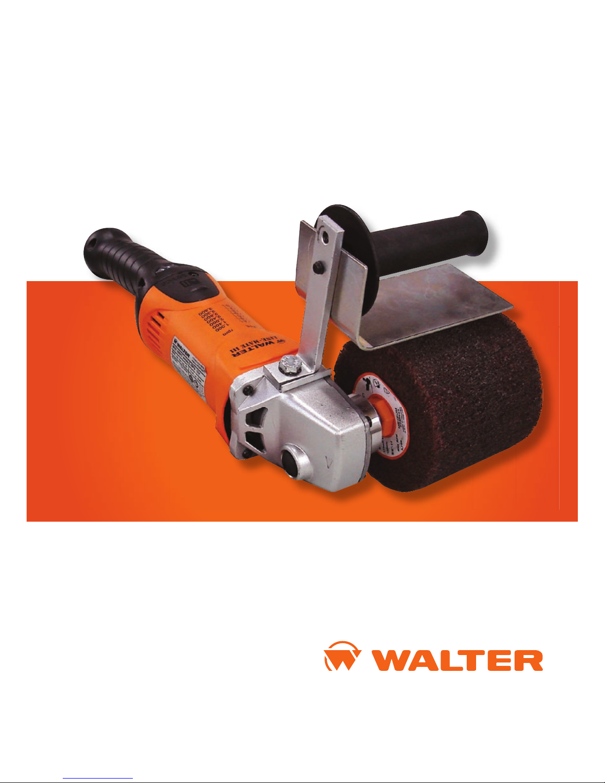
LINE-MATE III
(6268 C)
LINE FINISHING SYSTEM
SYSTÈME DE FINITION LIGNÉE
SISTEMA DE TERMINACION LINEAL
SISTEMA DE ACABAMENTO CIRCULAR
Page 2

LINE-MATE III
LINE FINISHING SYSTEM
(Model 6268 C)
ENGLISH
Page 3

1
Thank you for purchasing the LINE-MATE III
LINE FINISHING SYSTEM (Model 6268 C)
This operating instruction booklet has been designed to give you
all the information on the LINE-MATE III.
To ensure perfect functioning of your Line finishing system,
carefully read these instructions before using the tool.
Familiarize yourself with this tool’s operation, its particular
features, applications and limitations. You will also find useful
tips on safety and maintenance.
TITLES PAGES
Safety instructions ...................................................................................... 2
Introduction ................................................................................................ 8
Voltage .........................................................................................................
8
Extension cord ............................................................................................ 8
Technical Data ............................................................................................
9
Model illustration ....................................................................................... 10
Side handle & safety guard ......................................................................... 10
Spindle lock ................................................................................................ 10
Switch ......................................................................................................... 10
Dialspeed TM selector ................................................................................... 11
Dialspeed TM settings .................................................................................... 11
Dynamax TM Electronics .............................................................................. 11
Operation .................................................................................................... 12
Line finishing accessories ...........................................................................
12
Drums ......................................................................................................... 13
Pipe Finishing Abrasives ............................................................................
16
Carbon brushes ........................................................................................... 17
Preventive maintenance .............................................................................. 17
Warranty policy ..........................................................................................
18
WALTER Sales and Service .......................................................................
19
Page 4

2
3
General safety rules
Every WALTER power tool is produced in accordance with applicable
standards governing the manufacture, performance and safety of power
tools.
WARNING – To reduce the risk of injury, user
must read instruction manual.
Read all instructions. Failure to follow all instructions listed below may
result in electric shock, fire and/or serious injury. The term “power tool”�in
all of the warnings listed below refers to your mains-operated (corded)
power tool or battery-operated (cordless) power tool.
SAVE THESE INSTRUCTIONS
1) Work area safety
a) Keep work area clean and well lit. Cluttered or dark areas invite
accidents.
b) Do not operate power tools in explosive atmospheres, such as in
the presence of flammable liquids, gases or dust. Power tools create
sparks which may ignite the dust or fumes.
c) Keep children and bystanders away while operating a power tool.
Distractions can cause you to lose control
2) Electrical safety
a) Power tool plugs must match the outlet. Never modify the plug in
any way.
Do not use any adapter plugs with earthed (grounded) power tools.
Unmodified plugs and matching outlets will reduce risk of electric
shock.
b) Avoid body contact with earthed or grounded surfaces such as pipes,
radiators, ranges and refrigerators. There is an increased risk of
electric shock if your body is earthed or grounded.
c) Do not expose power tools to rain or wet conditions. Water entering a
power tool will increase the risk of electric shock.
d) Do not abuse the cord. Never use the cord for carrying, pulling or
unplugging the power tool. Keep cord away from heat, oil, sharp
edges or moving parts.
Damaged or entangled cords increase the risk of electric shock.
e) When operating a power tool outdoors, use an extension cord
suitable for outdoor use. Use of a cord suitable for outdoor use
reduces the risk of electric shock.
3) Personal safety
a) Stay alert, watch what you are doing and use common sense when
operating a power tool. Do not use a power tool while you are tired
or under the influence of drugs, alcohol or medication. A moment
of inattention while operating power tools may result in serious
personal injury.
b) Use safety equipment. Always wear eye protection. Safety
equipment such as dust mask, non-skid safety shoes, hard hat,
or hearing protection used for appropriate conditions will reduce
personal injuries.
c) Avoid accidental starting. Ensure the switch is in the off-position
before plugging in. Carrying power tools with your finger on the
switch or plugging in power tools that have the switch on invites
accidents.
d) Remove any adjusting key or wrench before turning the power tool
on. A wrench or a key left attached to a rotating part of the power
tool may result in personal injury.
e) Do not over-reach. Keep proper footing and balance at all times. This
enables better control of the power tool in unexpected situations.
f) Dress properly. Do not wear loose clothing or jewellery. Keep your
hair, clothing and gloves away from moving parts. Loose clothes,
jewellery or long hair can be caught in moving parts.
g) If devices are provided for the connection of dust extraction and
collection facilities, ensure these are connected and properly used.
Use of these devices can reduce dust-related hazards.
4) Power tool use and care
a) Do not force the power tool. Use the correct power tool for your
application.
The correct power tool will do the job better and safer at the rate for
which it was designed.
Page 5

4
5
below may result in electric shock, fire and/or serious injury.
b) Operations such as grinding or cutting-off are not recommended to
be performed with this power tool. Operations for which the power
tool was not designed may create a hazard and cause personal injury.
c) Do not use accessories which are not specifically designed and
recommended by Walter. Just because the accessory can be attached
to your power tool, it does not assure safe operation.
d) The rated speed of the accessory must be at least equal to the
maximum speed marked on the power tool. Accessories running
faster than their RATED SPEED can break and fly apart.
e) The outside diameter and the thickness of your accessory must
be within the capacity rating of your power tool. Incorrectly sized
accessories cannot be adequately guarded or controlled.
f) The arbour size of wheels, flanges, backing pads or any other
accessory must properly fit the spindle of the power tool. Accessories
with arbour holes that do not match the mounting hardware of the
power tool will run out of balance, vibrate excessively and may cause
loss of control.
g) Do not use a damaged accessory. Before each use inspect the
accessory such as abrasive wheels for chips and cracks, backing
pad for cracks, tear or excess wear, wire brush for loose or cracked
wires. If power tool or accessory is dropped, inspect for damage or
install an undamaged accessory. After inspecting and installing an
accessory, position yourself and bystanders away from the plane of
the rotating accessory and run the power tool at maximum no-load
speed for one minute. Damaged accessories will normally break
apart during this test time.
h) Wear personal protective equipment. Depending on application, use
face shield, safety goggles or safety glasses. As appropriate, wear
dust mask, hearing protectors, gloves and workshop apron capable of
stopping small abrasive or work piece fragments. The eye protection
must be capable of stopping flying debris generated by various
operations. The dust mask or respirator must be capable of filtrating
particles generated by your operation. Prolonged exposure to high
intensity noise may cause hearing loss.
i) Keep bystanders a safe distance away from work area. Anyone
b) Do not use the power tool if the switch does not turn it on and
off. Any power tool that cannot be controlled with the switch is
dangerous and must be repaired.
c) Disconnect the plug from the power source and/or the battery pack
from the power tool before making any adjustments, changing
accessories, or storing power tools. Such preventive safety measures
reduce the risk of starting the power tool accidentally.
d) Store idle power tools out of the reach of children and do not allow
persons unfamiliar with the power tool or these instructions to
operate the power tool. Power tools are dangerous in the hands of
untrained users.
e) Maintain power tools. Check for misalignment or binding of moving
parts, breakage of parts and any other condition that may affect the
power tool’s operation. If damaged, have the power tool repaired
before use. Many accidents are caused by poorly maintained power
tools.
f) Keep cutting tools sharp and clean. Properly maintained cutting
tools with sharp cutting edges are less likely to bind and are easier to
control.
g) Use the power tool, accessories and tool bits etc., in accordance with
these instructions and in the manner intended for the particular type
of power tool, taking into account the working conditions and the
work to be performed. Use of the power tool for operations different
from those intended could result in a hazardous situation.
5) Service
a) Have your power tool serviced by a qualified repair person using
only identical replacement parts. This will ensure that the safety of
the power tool is maintained.
Operation of this power tool
a) This power tool is intended to function as a sander, wire brush, or
polisher.
Read all safety warnings, instructions, illustrations and specifications
provided with this power tool. Failure to follow all instructions listed
Page 6

6
7
into the surface of the material causing the wheel to climb out or kick out.
The wheel may either jump toward or away from the operator, depending
on direction of the wheel’s movement at the point of pinching. Abrasive
wheels may also break under these conditions. Kickback is the result of
power tool misuse and/or incorrect operating procedures or conditions and
can be avoided by taking proper precautions as given below.
a) Maintain a firm grip on the power tool and position your body and
arm to allow you to resist kickback forces. Always use auxiliary
handle, if provided, for maximum control over kickback or torque
reaction during start-up. The operator can control torque reactions or
kickback forces, if proper precautions are taken.
b) Never place your hand near the rotating accessory. Accessory may
kickback over your hand.
c) Do not position your body in the area where power tool will move if
kickback occurs. Kickback will propel the tool in direction opposite
to the wheel’s movement at the point of snagging.
d) Use special care when working corners, sharp edges etc. Avoid
bouncing and snagging the accessory. Corners, sharp edges or
bouncing have a tendency to snag the rotating accessory and cause
loss of control or kickback.
e) Do not attach a saw chain woodcarving blade or toothed saw blade.
Such blades create frequent kickback and loss of control.
Safety Warnings Specific for Sanding Operations:
a) Do not use excessively oversized sanding disc paper. Follow
manufacturers recommendations, when selecting sanding paper.
Larger sanding paper extending beyond the sanding pad presents
a laceration hazard and may cause snagging, tearing of the disc or
kickback.
Safety Warnings Specific for Polishing Operations:
a) Do not allow any loose portion of the polishing bonnet or its
attachment strings to spin freely. Tuck away or trim any loose
attachment strings. Loose and spinning attachment strings can
entangle your fingers or snag on the work piece.
entering the work area must wear personal protective equipment.
Fragments of work piece or of a broken accessory may fly away and
cause injury beyond immediate area of operation.
j) Hold power tool by insulated gripping surfaces only, when
performing an operation where the cutting accessory may contact
hidden wiring or its own cord. Cutting accessory contacting a
“live”�wire may make exposed metal parts of the power tool “live”�
and shock the operator.
k) Position the cord clear of the spinning accessory. If you lose control,
the cord may be cut or snagged and your hand or arm may be pulled
into the spinning accessory.
l) Never lay the power tool down until the accessory has come to a
complete stop. The spinning accessory may grab the surface and pull
the power tool out of your control.
m) Do not run the power tool while carrying it at your side. Accidental
contact with the spinning accessory could snag your clothing, pulling
the accessory into your body.
n) Regularly clean the power tool’s air vents. The motor’s fan will draw
the dust inside the housing and excessive accumulation of powdered
metal may cause electrical hazards.
o) Do not operate the power tool near flammable materials. Sparks
could ignite these materials.
p) Do not use accessories that require liquid coolants. Using water or
other liquid coolants may result in electrocution or shock.
Further safety instructions for all operations
Kickback and Related Warnings
Kickback is a sudden reaction to a pinched or snagged rotating wheel,
backing pad, brush or any other accessory. Pinching or snagging
causes rapid stalling of the rotating accessory which in turn causes the
uncontrolled power tool to be forced in the direction opposite of the
accessory’s rotation at the point of the binding.
For example, if an abrasive wheel is snagged or pinched by the work
piece, the edge of the wheel that is entering into the pinch point can dig
Page 7
8
9
TECHNICAL DATA
MODEL 6268 C
Voltage .........................120 V AC; 60 Hz
Amperage .....................12
No-load speed ..............POS.A POS.B POS.C POS.D POS.E POS.F POS.G
.....................................1,000 1,400 2,000 2,400 2,800 3,300 3,800
Spindle Thread .............5/8“ -11 NC
Weight ..........................2,87 kg - 6lb. 5oz
MODEL 6268 C
Voltage .........................220 - 240 V AC; 50 - 60 Hz
Amperage .....................7,2
No-load speed ..............POS.A POS.B POS.C POS.D POS.E POS.F POS.G
.....................................1,000 1,400 2,000 2,400 2,800 3,300 3,800
Spindle Thread .............M14
Weight ..........................2,87kg - 6lb. 5oz
INTRODUCTION
Your WALTER power tool is precision built to meet the highest industrial
standards. For maximum performance and longest tool life, follow the
operating instructions and service procedures outlined in this manual.
This tool is CSA certified.
This tool is double insulated, it does not have to be grounded.
It may be safely operated from a grounded or ungrounded
receptacle. It is supplied with a 2-conductor power cord and a
polarized plug (one blade wider than the other). The plug will
fit only one way into a polarized outlet. If the plug does not fit,
have the outlet replaced by a qualified electrician. If an extension
cord is necessary, only one that is polarized must be used. Do
not change the plug in any way.
In order to maintain the safety features of the double insulation, the
housing must not be drilled to affix nameplates or the like. Self-adhesive
labels may be used for this purpose.
VOLTAGE
Before connecting the tool, make sure that the voltage shown on the rating
plate is the same as the power source.
Operating the tool on a voltage other than specified on its rating plate, may
result in personal injury to the user and damage to the unit.
EXTENSION CORD
When an extension cord is required, use one that is sufficient for the power
requirement of the tool. Extension cords of inadequate wire size cause a
serious drop in voltage, loss of power and possible motor damage. To limit
line voltage drop to a safe level, refer to the following table:
Length in meters 8 15 23 30
Length in feet 25 50 75 100
Wire size AWG 14 14 12 10
NOTE: Extension cords that are used outdoors must be approved for outdoor use.
Page 8
10
11
DIALSPEED™ SELECTOR
Select the required speed by rotating speed selector (8). Positions A-G
roughly equal the following no load revolutions per minute:
Pos. A B C D E F G
RPM
1,000 1,400 2,000 2,400 2,800 3,300 3,800
DIALSPEED™ SETTINGS
Set speed selector (8) to position D and adjust either up or down until you
have found a speed that meets your surface finishing requirements.
The correct setting will depend on:
a) Type of material being worked c) Amount of pressure being
applied
b) Abrasive accessory being used d) Surface finish required
DYNAMAX
™ ELECTRONICS
The built-in electronic feedback circuit continuously monitors the load on
the motor and adjusts power as required to maintain a virtually constant
speed.
Should the machine be subjected to overload for an extended period, for
example when being run at a lower speed setting, the rotation speed will be
decreased electronically to protect the motor, . The machine will not stop
completely, it will continue to run slowly to allow the motor to cool. After
a brief period, by switching the machine off and on again, it can then be
used again at the rated load.
When used for extended periods, it is quite normal for the machine to
become warm. The thermal overload protection described above will
auto-activate whenever necessary. With practice, the user will feel to what
extent the machine can be loaded at each speed setting for continuous
uninterrupted operation.
3
6
7
5
4
1
8
2
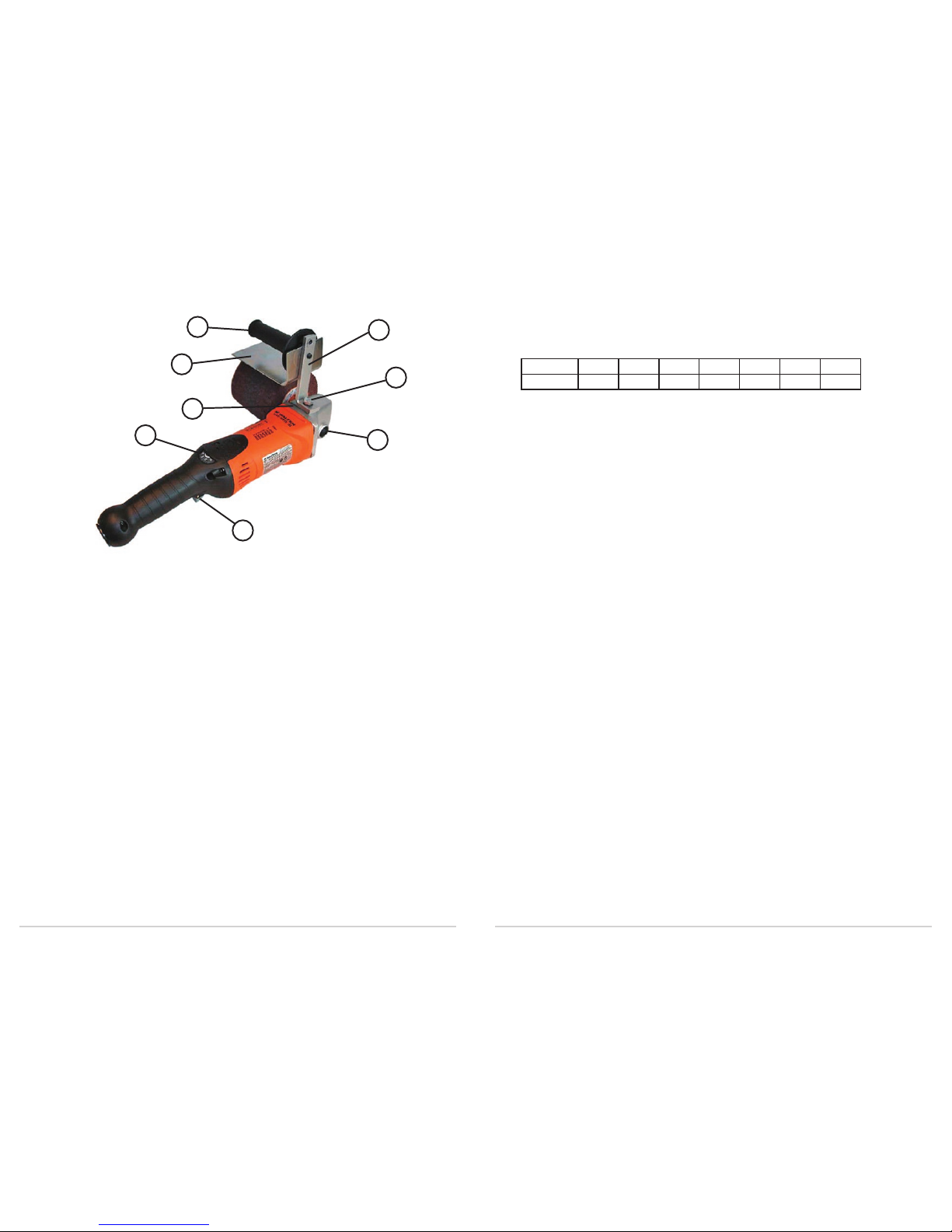
SIDE HANDLE AND SAFETY GUARD
Mount stabilizer (1) and handle bracket (2) to gear housing and secure
properly with bolt (3). Mount hand guard (4) and screw-in handle (5). For
reasons of safety and for better control, the hand guard and side handle
must always be used.
SPINDLE LOCK
To mount or remove drums and other accessories, disconnect the machine
from the power supply. Depress the locking button (6) located on top
of gear housing, while rotating the spindle by hand until the locking
mechanism is engaged. With the spindle in locked position, properly secure
the accessory being utilized. Never depress the locking button while the
tool is turned on.
SWITCH
To start, push locking switch (7) forward, locking it in the ON position.
To stop, press up on the long part of the switch, returning it to the OFF
position.
Page 9

12
13
Mounting Drum Belts
First, deflate bladder and check for a directional arrow on the inside of
the drum belt and match it with the arrow located on the outside flange of
the pneumatic drum. Slip on the selected drum belt and center it over the
drum. To secure belt, inflate bladder by applying air source to valve stem.
Inflate until drum belt feels snug, without over-inflating.
NOTE: a) Do not inflate bladder above 15 psi.
b)
When using shop air, be sure to use an approved blow-
gun
equipped with a safety nozzle.
COOLCUT
™ Drum Belts
These belts are made with premium zirconium and aluminum oxide
abrasive grains that are resin bonded to a heavy-duty cotton cloth. The
result is a cool aggressive rate of cut. Excellent for creating or restoring
line finishes, matching mill finishes and levelling small welds. These belts
are well suited as a starting point for further surface refinement.
Width Length Grit Order No.
3 1/2" 15 1/2" 40 07-F 364
3 1/2" 15 1/2" 60 07-F 366
3 1/2" 15 1/2" 80 07-F 368
3 1/2" 15 1/2" 120 07-F 371
5 3/8” 11 5/8" 40 07-F 504
5 3/8” 11 5/8" 60 07-F 506
5 3/8” 11 5/8" 80 07-F 508
5 3/8” 11 5/8" 120 07-F 511
NOTE: Prior to mounting the drum belt, verify that the directional arrow on the
inside of the drum belt matches the arrow located on the outside flange of the
pneumatic drum.
OPERATION
Please be sure to read and observe the “SAFETY INSTRUCTIONS” at
the beginning of this manual.
Always use the recommended safety guards when working with this power
tool.
Use only WALTER accessories with a maximum diameter of 7” and a
maximum safe operating speed of at least 4,500 RPM.
The use of any accessories and tooling other than those recommended may
be hazardous. Inspect all accessories and tooling before using. Do not use
any that may be damaged.
Screw all mounted accessories onto spindle and secure firmly with a
spanner.
For maximum performance and best efficiency, apply a steady and even
pressure. Do not use excessive force. Always wear eye protection.
LINE FINISHING ACCESSORIES
PNEUMATIC DRUMS
Width Dia. Arbor Max. RPM Order No.
5 3/8" 3 1/2" 5/8"-11 3,800 07-F 051
3 1/2" 5" 5/8"-11 3,800 07-F 037
Replacement rubber bladder assemblies
5 3/8" x 3 1/2" (for drum 07-F 051) 07-F 095
3 1/2" x 5" (for drum 07-F 037) 07-F 093
Replacement valve for all drums 07-F 010
The pneumatic drums will accept either COOLCUT™ or BLENDEX™ Drum
Belts.
The inflatable bladder conforms to the work piece for a more positive
surface contact.
Mounting Pneumatic Drums
Screw drum onto spindle and secure firmly. Once secured in place, the
pneumatic drum is ready to accept either COOLCUT ™ or BLENDEX™
drum belts.
Page 10

14
15
TWO-IN-ONE™ Drums
These drums combine 2 finishing steps into 1. Primarily designed for fine
finishing, they produce consistent results on both ferrous and non-ferrous
metals. The coated abrasive cloth cuts aggressively while the interleaved
BLENDEX™ flaps give the surface a satin finish.
Dia. Width Arbor Grit Order No.
4 1/4” 2” 5/8”-11 80 07-K 422
4 1/4” 4” 5/8”-11 80 07-K 442
BLENDEX™ Drums
These drums are designed to produce a wide range of decorative finishes
used for polishing, burnishing light blending and deburring, removing
shallow scratches and brightening. These non-woven flaps conform to flat
or curved work pieces giving consistent quality finishes, suitable for use on
all ferrous and non-ferrous metals.
Dia. Width Arbor Grit Order No.
4 1/4” 2” 5/8”-11 Coarse 07-M 422
4 1/4” 2” 5/8”-11 Medium 07-M- 423
4 1/4” 2” 5/8”-11 Fine 07-M 424
3 1/2” 2” 5/8”-11 Super Fine 07-M 425
4 1/4” 4” 5/8”-11 Coarse 07-M 442
4 1/4” 4” 5/8”-11 Medium 07-M 443
4 1/4” 4” 5/8”-11 Fine 07-M 444
4 1/4” 4” 5/8”-11 Super Fine 07-M 445
FX™ Drums
Designed for tough cleaning applications, these drums will strip paint with
ease, remove rust and scale, and clean-up a variety of surfaces. The open
web-like construction assures cool operations that resist loading for greater
productivity. These drums can replace wire brushes and sand blasting
operations.
Dia. Width Arbor Grit Order No.
4 1/4” 2” 5/8”-11 Coarse 07-L 420
4 1/4” 4” 5/8”-11 Coarse 07-L 440
BLENDEX™ Drum Belts
These surface conditioning drum belts will quickly clean, refine and
condition large metal surfaces. They will produce a wide range of finishes
such as polishing, buffing, matching mill satin, burnishing and also
eliminating scratches.
They produce a consistent and uniform brushed finish on stainless steel,
steel, aluminum and other non-ferrous metals.
Width Length Grit/Color Order No.
3 1/2” 15 1/2” Coarse - Tan 07-H 362
3 1/2” 15 1/2” Medium - Maroon 07-H 363
3 1/2” 15 1/2” Fine - Blue 07-H 364
3 1/2” 15 1/2” Super Fine - Grey 07-H 365
5 3/8” 11 5/8" Coarse - Tan 07-H 502
5 3/8” 11 5/8" Medium - Maroon 07-H 503
5 3/8” 11 5/8" Fine - Blue 07-H 504
5 3/8” 11 5/8" Super Fine - Grey 07-H 505
COOLCUT™ Flap Drums
These drums are recommended where light metal removal and graining is
required. They remove light casting/forging lines, small weld seams and
are excellent for components with contours. They are as effective as the
first step of the final finishing process.
Dia. Width Arbor Grit Order No.
4 1/4” 2” 5/8”-11 40 07-J 424
4 1/4” 2” 5/8”-11 60 07-J 426
4 1/4” 2” 5/8”-11 80 07-J 428
4 1/4” 2” 5/8”-11 120 07-J 432
4 1/4” 4” 5/8”-11 40 07-J 444
4 1/4” 4” 5/8”-11 60 07-J 446
4 1/4” 4” 5/8”-11 80 07-J 448
4 1/4” 4” 5/8”-11 120 07-J 452
Page 11

16
17
Buffing Drums
Heavy cotton drums used with polishing pastes.
Ideal for enhancing and brightening existing finishes, taking out stains in
metals and bringing outa new lustre in work surfaces.
Optimal working speed 1700-2200 RPM.
Dia. Width Arbor Grit Order No.
4 3/4” 2” 5/8”-11 Multi-ply cotton 07-T 425
PIPE FINISHING ABRASIVES
BLENDEX™ Strip Belts
Quick and efficient method to produce in-line finishes on small diameter
tubing and pipes made of steel, stainless steel and aluminum.
- Produce new sheen and lustre in tarnished pipe work.
- Ideal for enhancing and brightening existing finishes, taking out
stains in metals and bringing out a new lustre in work surfaces.
Width Length Grit/Color Order No.
1 3/16” 25” Coarse - Tan 07-H 242
1 3/16” 25” Medium - Maroon 07-H 243
1 3/16” 25” Fine - Blue 07-H 244
1 3/16” 25” Super Fine - Grey 07-H 245
Belt Drive Rollers
For use with BLENDEX™ Conditioning Strip Belts. This belt drive roller
is made of resistant polyurethane. The ribbed design ensures positive drive
of belts. The large stainless steel side plates prevent belts from slipping
off.
CARBON BRUSHES
When the carbon brushes are worn down, the Auto-Stop feature will
automatically turn the machine off in order not to damage the motor. The
brushes must then be replaced.
Use only genuine WALTER carbon brushes. These brushes are specially
made for this tool. They will maintain their high performance standard and
ensure maximum life of the motor.
To check or replace carbon brushes:
1. Disconnect the tool from power supply.
2. Unscrew and remove carbon brush service window.
3. Carbon brushes may be pulled from their holders after lifting spring
and detaching the connector.
4. Replace brushes if necessary. Always replace them in pairs.
5. Check that the new brushes move freely in their holders. To help seat
the carbon brushes properly after they have been installed, use the
power tool without applying a heavy load for at least 30 minutes.
However, when the carbon brushes require replacement, it is recommended
that the tool be sent to a WALTER Factory Service Center or a WALTER
Authorized Service Center. Apart from changing the brushes, your power
tool will be cleaned, inspected and lubricated as required.
PREVENTIVE MAINTENANCE
Your WALTER power tool should be properly maintained to insure
continued high performance.
Use low-pressure compressed air to blow out dust from the motor through
the vent openings.
Clean dust and dirt deposits from the exterior of the tool. Clean the power
cord to prevent deterioration from oil and grease and check for possible
damage to cord or plug.
NOTE: Damaged cord sets must be replaced. Refer to Spare Parts List for
the ordering number.
Page 12

18
19
WARRANTY POLICY
All WALTER power tools and accessories are inspected and tested before
shipping and are guaranteed to be free from any defect in material and
faulty workmanship. Should any malfunction occur within one (1) year
from the date of original purchase, return the complete tool prepaid with
proof of purchase, to the nearest WALTER Factory or Authorized Service
Center. If an examination shows that the malfunction was caused by
defective material or faulty workmanship, WALTER will repair (or at our
option, replace) without charge. This warranty does not apply when normal
maintenance is required, repairs or replacements have been made or were
attempted by anyone other than WALTER authorized service personnel,
and does not cover any damage caused by accidents, modifications, use of
improper accessories, abuse or misuse, which also includes overloading
the tool beyond its rated capacity as well as its continued use after partial
failure. No other warranty, written or verbal is authorized.
In no event shall WALTER be liable for any indirect, incidental or
consequential damages from the sale of the product. This disclaimer
applies both during and after the term of this warranty.
This warranty gives you specific rights. The provisions contained in this
warranty are not intended to limit, modify, take away from, disclaim or
exclude any warranties set forth in any Provincial or State legislation.
To the extent required by law, the provisions in any Provincial, State or
Federal legislation with respect to warranties take precedence over the
provisions in this warranty.
WALTER SALES AND SERVICE
CANADA
MONTREAL:
5977 Trans Canada Highway
Pointe-Claire QC H9R 1C1
Tel.: (514) 630-2801
Fax: (514) 630-2825
TORONTO:
151 Superior Blvd., Unit 12
Mississauga ON L5T 2L1
Tel.: (905) 795-8555
Fax: (905) 795-8558
VANCOUVER:
1-1595 Cliveden Avenue
Delta BC V3M 6M2
Tel.: (604) 540-4777
Fax: (604) 540-4778
U.S.A.
WINDSOR:
J. Walter Inc.
810 Day Hill Road
Windsor CT 06095-1704
Tel: (860) 298 1100
Fax: (860) 274 4435
BRAZIL
SAO PAULO
Walter Indústria e Comércio Ltda.
Rua Marco Gianini, 426
Butantã, São Paulo, SP
CEP: 05550-000
Tel.: (5511) 3783.9500
Fax: (5511) 3783.9501
ARGENTINA
BUENOS AIRES
Walter S.A.
Dardo Rocha 1032/34
B1754FCD) San Justo
Tel.: (54-11)4441-1889/1648
Fax: (54-11)4441-0258
MEXICO
JALISCO
Walter
Boulevard La Carreta No. 835
PARQUE INDUSTRIAL
BELENES NORTE
CP 45145 Zapopan
Tel.: (52) 33 11 99 15 15
Fax: (52) 01 800 087 51 19
In Canada call toll free 1-888-JWALTER and in the U.S.A. 1-866-JWALTER for the location of
an Authorized Service Center closest to you or visit our web site: www.walter.com.
Page 13
LINE-MATE III
SYSTÈME DE FINITION LIGNÉE
(Modèle 6268 C)
FRANÇAIS
Page 14

1
Nous vous remercions d’avoir choisi le LINE-MATE III
SYSTÈME DE FINITION LIGNÉE (Modèle 6268C)
Plus vous serez familiarisé avec le Line-Mate III, mieux
vous pourrez exploiter cet appareil.
C’est pourquoi nous vous prions de lire attentivement
ce mode d’emploi avant de mettre le l’outil en service.
Vous y trouverez des indications importantes pour une
utilisation sans problème, ainsi que des informations
importantes relatives à la sécurité et à la maintenance
du Line-Mate III.
TITRES PAGE
Directives de sécurité .................................................................................. 2
Introduction ................................................................................................ 9
Voltage .........................................................................................................
9
Rallonge électrique ..................................................................................... 10
Caractéristiques Techniques .......................................................................
10
Illustration du modèle ................................................................................. 11
Poignée latérale ........................................................................................... 11
Dispositif de blocage de l’arbre .................................................................. 11
Interrupteur ................................................................................................. 11
Sélecteur de vitesses Dialspeed MC ...........................................................
12
Réglage Dialspeed MC ...............................................................................
12
Électronique Dynamax MC .........................................................................
12
Fonctionnement .......................................................................................... 13
Accessoires pour la finition lignée ..............................................................
13
Tambours ....................................................................................................
15
Abrasifs pour la finition de tuyaux .............................................................
17
Entretien préventif ...................................................................................... 18
Politique de garantie ................................................................................... 19
Ventes et service WALTER .........................................................................
20
Page 15

2
3
Consignes de sécurité générales
Les outils électriques Walter sont fabriqués selon les normes établies
régissant la fabrication, le fonctionnement et la sécurité des outils
électriques.
MISE EN GARDE : Afin de réduire le risque de blessures,
l’utilisateur doit lire attentivement le mode d’emploi.
Veuillez lire toutes les instructions. Il est important de suivre les
instructions énumérées afin de réduire le risque de chocs électriques,
d’incendie et/ou de blessures graves. Le terme « outil électrique » dans
toutes les mises en garde énumérées fait référence à votre outil électrique
avec ou sans fil (muni d’une pile).
CONSERVEZ CES INSTRUCTIONS
1) Sécurité dans votre zone de travail
a) Gardez votre zone de travail propre et bien éclairée. Un milieu
de travail en désordre ou mal éclairé peut devenir une source
d’accidents.
b) Ne pas utiliser l’outil électrique dans des atmosphères explosives, par
exemple en présence de liquide inflammable, de gaz ou de poussière.
L’outil électrique en fonction crée des étincelles et pourrait enflammer
la poussière ou les vapeurs.
c) Éloigner les enfants et les passants lors de l’utilisation d’un outil
électrique. Les distractions peuvent vous faire perdre le contrôle.
2) Sécurité en électricité
a) La fiche de l’outil électrique doit correspondre à la prise de courant.
Ne jamais modifier la fiche d’aucune façon. N’utilisez pas de
raccords de fiches avec des outils électriques mis à la terre. Les
fiches originales et les prises correspondantes réduiront le risque de
chocs électriques.
b) Évitez tout contact avec les surfaces mises à la terre, tels les tuyaux,
les radiateurs, les cuisinières et les réfrigérateurs. Le risque de chocs
électriques augmente si votre corps est relié à la terre.
c) Ne pas utiliser l’outil électrique sous la pluie ou dans des endroits
humides. L’infiltration d’eau dans l’outil augmente le risque de chocs
électriques.
d) N’abusez pas du cordon électrique. Ne transportez jamais l’outil en
le tenant par le cordon électrique et ne le débranchez pas en tirant sur
le cordon.Tenir le cordon loin de la chaleur, de l’huile et des pièces
tranchantes ou en mouvement. Un cordon endommagé ou enchevêtré
augmente le risque de chocs électriques.
e) Lorsque vous utilisez l’outil en plein air, assurez-vous d’avoir une
rallonge conçue pour une utilisation extérieure, réduisant ainsi le
risque de chocs électriques.
3) Sécurité personnelle
a) Soyez vigilant en tout temps lorsque vous manipulez un outil
électrique et faites preuve de bons sens. N’utilisez pas l’outil lorsque
vous êtes fatigué ou sous l’influence de l’alcool, de drogues ou
de médicaments. Un seul moment d’inattention dans l’utilisation
d’outils électriques peut entraîner des blessures graves.
b) Utilisation de matériel de sécurité – Il est important de toujours
porter des lunettes de sécurité. Le matériel de sécurité, y compris
un masque, des chaussures de sécurité antidérapantes, un casque de
sécurité et des tampons pour oreilles, évite les blessures.
c) Évitez un démarrage involontaire. Assurez-vous que l’interrupteur
est à la position « OFF » avant de le brancher. Le fait de transporter
l’outil avec votre doigt sur l’interrupteur ou de brancher l’outil
lorsque l’interrupteur est à « ON » peut provoquer des accidents.
d) Avant d’actionner l’outil électrique, assurez-vous de retirer toutes
les clés et les outils de réglage. Une clé attachée aux pièces en
mouvement d’un outil électrique peut provoquer des blessures.
e) Ne travaillez pas à bout de bras. Gardez un bon équilibre en tout
temps. Cela permet un meilleur contrôle de l’outil électrique dans
des situations imprévues.
f) Portez des vêtements appropriés. Évitez de porter des bijoux et des
vêtements amples lorsque vous travaillez avec des outils électriques.
Gardez vos cheveux, vos vêtements et vos gants loin des pièces en
mouvement. Les vêtements amples, les bijoux ou les cheveux longs
peuvent s’entremêler dans les pièces en mouvement.
Page 16

4
5
g) Si des dispositifs de connexion sont fournis pour l’extraction et la
collecte de poussière, assurez-vous de bien les raccorder et de les
utiliser correctement. L’utilisation de ces dispositifs peut réduire les
risques engendrés par la poussière.
4) Utilisation et entretien de l’outil
a) Ne pas forcer l’outil au-delà de sa capacité. Utilisez l’outil approprié
pour l’application requise. L’utilisation du bon outil, conçu pour
l’application désirée, donnera de meilleurs résultats et sera plus
sécuritaire.
b) Ne pas utiliser l’outil lorsqu’il est impossible de positionner
l’interrupteur à « ON » ou à « OFF ». Tout outil électrique qui ne
peut être contrôlé à l’aide de l’interrupteur n’est pas sécuritaire;
celui-ci doit être réparé.
c) Débranchez la fiche de la source électrique et/ou enlevez la batterie
de l’outil avant de faire des ajustements, de changer d’accessoires ou
lorsque vous le ranger. Cette mesure de sécurité prévient le risque
d’un démarrage accidentel de l’outil.
d) Remisez vos outils électriques hors de la portée des enfants et
empêchez quiconque n’est pas familier avec les instructions et le
fonctionnement de l’outil de l’utiliser. Il est dangereux de laisser des
outils électriques dans les mains d’utilisateurs inexpérimentés.
e) Faites l’entretien des outils électriques. Vérifiez l’alignement,
l’état des pièces mobiles, le bris de pièces et toute autre condition
qui pourrait influencer le bon fonctionnement de l’outil. Si celuici est endommagé, assurez-vous de le réparer avant de l’utiliser.
Plusieurs accidents sont attribuables au manque d’entretien des outils
électriques.
f) Gardez les outils de coupe bien affûtés et propres. Le bon entretien
de votre outil de coupe sera moins susceptible de se coincer et plus
facile à manœuvrer.
g) Utilisez l’outil électrique, les accessoires et forets selon ces
instructions et de la façon prévue pour le type particulier d’outil
électrique, tenant compte des conditions de travail et du travail à
accomplir. L’utilisation de l’outil électrique pour des applications
autre que celles qui lui sont destinées pourrait entraîner un danger.
5) Entretien
a) Assurez-vous que l’entretien de votre outil électrique soit effectué
par un technicien qualifié qui utilise des pièces de remplacement
originales. Cela assurera un fonctionnement sécuritaire de l’outil.
Utilisation de l’outil électrique
a) Cet outil est destiné à servir de sableuse ou de polisseuse; il est
muni d’une brosse d’acier. Veuillez lire les mises en garde, le mode
d’emploi, les particularités et les schémas fournis avec cet outil
électrique. Il est important de suivre les instructions énumérées plus
bas afin de réduire le risque de chocs électriques, d’incendie et/ou de
blessures graves.
b) Il n’est pas recommandé d’utiliser cet outil pour meuler, tronçonner
ou effectuer des travaux de ce genre. Les travaux ne convenant pas à
l’outil peuvent entraîner un risque de danger et de blessures.
c) Ne pas utiliser les accessoires qui ne sont pas précisément conçus
et recommandés par Walter. Sachez que même si un accessoire
peut être raccordé à votre outil électrique, ceci n’assure pas
nécessairement sa sécurité d’utilisation.
d) La vitesse approuvée de l’accessoire doit correspondre au moins à
la vitesse maximale indiquée sur l’outil. Utiliser l’accessoire à une
vitesse supérieure à celle APPROUVÉE peut provoquer le bris et
l’éclatement de l’accessoire.
e) L’épaisseur et le diamètre extérieur de l’accessoire doivent figurer
dans l`indice de capacité de votre outil électrique. Les accessoires
de taille inappropriée ne peuvent être convenablement surveillés ou
contrôlés.
f) La dimension de l`arbre, de la bride, des tampons de soutien ou de
tout accessoire doit s’ajuster adéquatement au mandrin de l’outil
électrique. Les accessoires dont les trous de fixation de l’arbre ne
correspondent pas aux pièces de montage de l’outil électrique seront
en déséquilibre, présenteront une vibration excessive et pourront
entraîner une perte de contrôle.
g) Ne pas utiliser un accessoire endommagé. Avant chaque utilisation,
vérifiez l’état des accessoires, notamment les meules abrasives
Page 17

6
7
pour repérer les ébréchures et les fissures, les tampons de soutien
pour repérer des déchirures ou une usure excessive et les brosses
métalliques pour repérer des fils brisés ou endommagés. Si l’outil
ou l’accessoire est échappé, vérifier la présence de dommages ou
installer un nouvel accessoire. Suite à cette inspection et l’installation
du nouvel accessoire, tenez-vous (et les passants) hors de portée du
rabot de l’accessoire rotatif et mettez le moteur de l’outil en marche
à la position maximale « à vide » pendant une minute. En général, un
accessoire endommagé se brisera durant cette période d’essai.
h) Portez un équipement de protection. Selon l’application, utilisez une
visière ou des lunettes de sécurité. Utilisez un masque anti-poussière,
des protecteurs auditifs, des gants et un tablier d’atelier afin de
vous protéger de petites pièces abrasives or fragments. Les lunettes
de sécurité doivent couvrir suffisamment les yeux pour éviter
l’infiltration de débris générés par diverses applications de l’outil.
Le masque anti-poussières doit pouvoir filtrer les particules générées
lors de vos travaux exécutés avec l’outil. Une exposition prolongée
au bruit très intense peut entraîner une perte auditive.
i) Gardez les passants à une distance sécuritaire de votre zone de
travail. Toute personne qui accède à la zone de travail doit porter un
équipement de protection. Des fragments de pièces ou d’accessoire
brisé peuvent voler en éclats et causer des blessures au-delà de la
zone immédiate des travaux.
j) Toujours tenir l’outil électrique par la poignée et/ou le boîtier isolés
durant les travaux alors que l’accessoire de coupe peut entrer en
contact avec son propre cordon d’alimentation ou atteindre des fils
électriques dissimulés. Un accessoire tranchant qui touche un fil
électrique pourrait ainsi exposer les parties métalliques, ce qui risque
de donner un choc électrique à l’utilisateur.
k) Placez le cordon d’alimentation hors de la portée de l’accessoire
rotatif. Si vous perdrez le contrôle, le cordon peut être coupé ou
se détacher et entraîner votre main ou votre bras dans l’accessoire
rotatif.
l) Ne jamais déposer l’outil avant qu’il soit entièrement arrêté.
L’accessoire rotatif pourrait saisir la surface et ainsi causer la perte
de contrôle.
m) Ne jamais transporter l’outil lorsqu’il est en marche. L’accessoire
rotatif qui entrerait en contact accidentellement à vos vêtements
pourrait causer des blessures.
n) Nettoyez régulièrement le dispositif de ventilation de l’outil
électrique. Le ventilateur du moteur laissera de la poussière s’infiltrer
dans l’enveloppe. L’accumulation excessive de poussière métallique
peut alors causer des risques d’origine électrique.
o) Ne pas utiliser l’outil à proximité de matières inflammables. Des
étincelles pourraient enflammer ces matières.
p) Ne pas utiliser d’accessoires qui nécessitent un liquide de
refroidissement. Utiliser de l’eau ou d’autres liquides de
refroidissement pourrait provoquer l’électrocution ou un choc
électrique.
Autres directives de sécurité pour toutes les applications
Les rebonds et les mises en garde
L’effet de rebond est une réaction soudaine provoquée par le coincement
ou l’accrochage d’une meule en rotation, du tampon de soutien ou de tout
autre accessoire. Le coincement ou l’accrochage cause un freinage rapide
qui incite l’outil à se diriger dans la direction opposée de la rotation.
Par exemple, lorsqu’une meule abrasive s’accroche ou se coince dans
la pièce, le rebord de la meule qui pénètre la surface du matériel fait
remonter ou rebondir la meule. Il est possible que la meule rebondisse vers
l’utilisateur ou s’en éloigne, selon la direction du mouvement de la meule
au point de coincement. Les meules abrasives peuvent aussi de briser dans
ces conditions. Le rebond est le résultat d’une mauvaise utilisation de
l’outil électrique et/ou des procédures inappropriées ou du mauvais état
de fonctionnement. Cela peut être évité en prenant les bonnes précautions
indiquées plus bas.
a) Tenez l’outil fermement et placez votre corps et votre bras de
manière à pouvoir résister aux forces de rebond. Utiliser toujours la
poignée auxiliaire, si disponible, afin d’exercer un contrôle maximal
du rebond ou de la réaction de couple au démarrage. L’opérateur peut
contrôler les réactions de couple ou les forces du rebond, s’il prend
les mesures appropriées.
Page 18

8
9
b) Ne placez jamais votre main près de l’accessoire rotatif. L’accessoire
peut rebondir sur votre main.
c) Ne placez pas votre corps dans la zone où l’outil électrique se
déplacera s’il survient un rebond. Le rebond propulsera l’outil en
direction opposée au mouvement de la meule au point d’accrochage.
d) Soyez vigilants lorsque vous travaillez les coins, les bords coupants,
etc. Évitez de faire rebondir et d’accrocher l’accessoire. Les coins,
les bords coupants ou le rebond ont tendance à accrocher l’accessoire
rotatif et provoquer une perte de contrôle ou un rebond.
e) N’attachez pas de lame de sculpture sur bois à chaîne ou de lame de
scie à dents. Ce genre de lames occasionnent souvent un rebond et
une perte de contrôle.
Mises en garde de sécurité particulières aux travaux de sablage :
a) N’utilisez pas du papier abrasif trop grand. Respectez les
recommandations du fabricant dans votre choix de papier abrasif.
Du papier abrasif trop grand qui dépasse le patin ponceur présente
un risque de lacération et peut occasionner l’accrochage et le
déchirement du disque ou un effet de rebond.
Mises en garde de sécurité particulières aux travaux de polissage :
a) Ne laissez aucune pièce lâche du couvercle de polissage ou ses
cordes de fixation tourner librement. Rentrez ou coupez toute corde
de fixation lâche. Les cordes de fixation lâches et en rotation peuvent
s’entremêler à vos doigts ou s’accrocher à la pièce.
INTRODUCTION
Votre outil WALTER est fabriqué avec précision selon les normes
industrielles les plus élevées. Pour un rendement optimal et une plus
longue durée de vie, veuillez suivre les directives de mise en marche et
d’entretien décrites dans ce manuel.
Cet outil est certifié CSA.
Cet outil est doublement isolé, il ne doit pas être mis à la terre.
Il peut être raccordé sans risque à une prise de courant mise à la
terre ou non mise à la terre. Il est fourni avec un câble à deux
(2) conducteurs et une fiche polarisée (une lame plus large que
l’autre). La fiche entrera dans une seule direction dans une prise
de courant polarisée. Si la fiche ne convient pas, faites remplacer
la prise de courant par un électricien qualifié. Si une rallonge
électrique est nécessaire, vous devez en utiliser une qui soit
polarisée. Ne changez en aucune façon la prise de courant.
Afin de maintenir les avantages sécuritaires de la double isolation,
le boîtier du moteur ne doit pas être perforé pour y fixer des plaques
d’identification. Utilisez plutôt des étiquettes auto-adhésives.
VOLTAGE
Avant de brancher l’outil, veuillez vous assurer que le voltage inscrit sur la
plaque de l’outil est le même que celui de la source électrique.
L’utilisation de l’outil à un voltage autre que celui spécifié pourrait causer
des blessures et endommager l’outil.
Page 19

10
11
RALLONGE ÉLECTRIQUE
Lorsqu’une rallonge électrique est requise, utilisez un câble ayant un
diamètre suffisant pour accommoder les besoins en courant de votre outil.
Des rallonges électriques ayant une grosseur de fil insuffisante causent
une perte de voltage importante ainsi qu’une perte d’énergie et peuvent
endommager le moteur.
Afin de limiter la perte de voltage à un niveau modéré, veuillez consulter la
table suivante.
Longueur en mètres 8 15 23 30
Longueur en pieds 25 50 75 100
Grosseur de fil AWG 14 14 12 10
NOTE :
Toutes les rallonges utilisées à l’extérieur doivent être approuvées pour un usage
extérieur.
CARACTÉRISTIQUES TECHNIQUES
MODEL 6268 C
Tension ......................... 120 V AC; 60 Hz
Ampéres ....................... 12
Vitesse de rotation .......POS.A POS.B POS.C POS.D POS.E POS.F POS.G
.....................................1,000 1,400 2,000 2,400 2,800 3,300 3,800
Filet d‘arbre .................5/8“ -11 NC
Poids ............................2,87kg - 6lb. 5oz
MODEL 6268 C
Tension ......................... 220 - 240 V AC; 50 - 60 Hz
Ampéres ....................... 7,2
Vitesse de rotation .......POS.A POS.B POS.C POS.D POS.E POS.F POS.G
.....................................1,000 1,400 2,000 2,400 2,800 3,300 3,800
Filet d‘arbre .................M14
Poids
.................................
2,87kg - 6lb. 5oz
3
6
7
5
4
1
8
2
POIGNÉE LATÉRALE & PROTÈGE-MAIN
Montez le stabilisateur (1) et le support de la poignée (2) sur le boîtier
d’engrenages et fixez correctement avec le boulon (3). Montez le protègemain (4) et vissez la poignée (5). Pour des raisons de sécurité et un
meilleur contrôle, le protège-main et la poignée latérale doivent toujours
être utilisés.
DISPOSITIF DE BLOCAGE DE L’ARBRE
Pour monter ou enlever les tambours et autres accessoires, débranchez
l’unité de la prise électrique. Enfoncez le dispositif de blocage de l’arbre
situé sur le dessus du boîtier d’engrenages (6) , tout en faisant pivoter
l’arbre à la main jusqu’à ce que le mécanisme de blocage soit engagé.
Avec l’arbre dans une position de blocage, sécurisez correctement
l’accessoire utilisé. Ne jamais enfoncer le bouton de blocage si l’outil est
activé
INTERRUPTEUR
Pour mettre en marche, poussez la glissière (7) vers l’avant, la verrouillant
à la position “ON”. Pour arrêter, pressez vers l’arrière, retournant à la
position “OFF”.
Page 20

12
13
SÉLECTEUR DE VITESSES DIALSPEED
MC
Sélectionnez la vitesse requise en pivotant le sélecteur de vitesses (8). Les
positions A-G équivalent environ aux révolutions par minute suivantes:
Pos. A B C D E F G
RPM
1,000 1,400 2,000 2,400 2,800 3,300 3,800
RÉGLAGE DIALSPEED
MC
Mettre le sélecteur de vitesse à ( 8) position D et ajustez vers le haut ou
vers le bas jusqu’à ce que vous ayez atteint la vitesse qui rencontre vos
exigences de finition de surfaces.
Le bon réglage dépendra de: a) Type de matériau
b) Accessoire abrasif utilisé
c) Quantité de pression
d) Finition requise
ÉLECTRONIQUES DYNAMAX
MC
Cet outil est muni d’un circuit d’alimentation électronique. La charge du
moteur ainsi que l’alimentation en énergie requise sont continuellement
contrôlées afin de maintenir une vitesse quasi constante.
Si la machine est soumise à une forte pression durant une période
prolongée, par exemple, lorsque l’appareil fonctionne à basse vitesse,
la rotation du moteur sera électroniquement diminué afin de protéger
le moteur. Plutôt que d’arrêter complètement, le moteur continuera son
fonctionnement à une vitesse réduite afin de refroidir ( protection de
surcharge thermique). Après un court moment, mettez l’appareil hors
tension pour ensuite le redémarrer. Suivant ces étapes, l’appareil peut être
utilisé de nouveau à une charge nominale.
Lorsque l’appareil est utilisé pendant de longues périodes, il est tout à
fait normal qu’il devienne chaud. La fonction de protection de surcharge
thermique, tel que décrit ci-dessus, s’activera automatiquement lorsque
nécessaire. À l’usage, l’utilisateur saura reconnaître à quelle vitesse et avec
quel pression l’outil performera le mieux pour un fonctionnement continu
et sans interruption.
FONCTIONNEMENT
Veuillez bien lire et suivre les “DIRECTIVES DE SÉCURITÉ’’ décrites
au début de ce manuel.
Toujours utiliser les protège-meules recommandés quand vous travaillez
avec cet outil électrique.
Utilisez seulement des accessoires WALTER ayant un diamètre maximal de
7” et une vitesse de fonctionnement sécuritaire maximale d’au moins 4,500
RPM.
Inspectez tous les accessoires et outillage avant l’utilisation. Ne pas utiliser
ceux qui pourraient être endommagés.
Vissez tous les accessoires montés sur l’arbre et fixez fermement avec une
clé à ergot.
Pour une performance et une efficacité optimales, maintenez une pression
uniforme et constante. Évitez de trop forcer. Utilisez toujours des lunettes
de protection.
ACCESSOIRES POUR FINITION LIGNÉE
TAMBOURS PNEUMATIQUES
Largeur Dia. Arbre RPM Max. N° de comm.
5 3/8" 3 1/2" 5/8"-11 3,800 07-F 051
3 1/2" 5" 5/8"-11 3,800 07-F 037
Ensemble de rechange de gaines en caoutchouc:
5 3/8" x 3 1/2" (pour tambours 07-F 051) 07-F 095
3 1/2" x 5" (pour tambours 07-F 037) 07-F 093
Soupape de rechange pour tous les tambours 07-F 010
Le tambour pneumatique acceptera les courroies de tambours COOLCUT MC
ou BLENDEX MC. La gaine gonflable s’adapte à la pièce à travailler pour un
meilleur contact à la surface.
Page 21

14
15
Montage des tambours pneumatiques
Vissez le tambour sur l’arbre et fixez fermement. Une foix fixé, le tambour
pneumatique est prêt pour les courroies de tambours COOLCUT MC ou
BLENDEX MC.
Montage des courroies de tambours
Premièrement, dégonflez la gaine et trouvez la flèche directionnelle à
l’intérieur de la courroie et alignez-la avec celle située à l’extérieur de
la rondelle du tambour pneumatique. Glissez la courroie sélectionnée
et centrez-la sur le tambour. Pour fixer la courroie, gonflez la gaine en
appliquant une source d’air dans la tige de la soupape. Gonflez jusqu’à ce
que la courroie soit bien ajustée, mais ne pas trop gonfler.
NOTE: a) Ne pas gonfler la gaine au-dessus de 15 psi.
b) Assurez-vous d’utiliser une pompe approuvé et équipé
d’unembout de sûreté.
Courroies de tambours COOLCUT
MC
Ces courroies sont fabriquées avec des grains de la meilleure qualité
d’abrasifs de zirconium et d’oxyde d’aluminium qui sont agglomérés sur
un matériau coton très résistant, lequel donne comme résultat un taux
de coupes agressif et froid. Excellent pour créer ou restaurer des finis
lignés, finis procédés en usine et mettre à niveau les petites soudures.
Ces courroies sont bien appropriées comme point de départ pour une
amélioration de surfaces.
Largeur Longueur Grain N° de comm.
3 1/2" 15 1/2" 40 07-F 364
3 1/2" 15 1/2" 60 07-F 366
3 1/2" 15 1/2" 80 07-F 368
3 1/2" 15 1/2" 120 07-F 371
5 3/8” 11 5/8" 40 07-F 504
5 3/8” 11 5/8" 60 07-F 506
5 3/8” 11 5/8" 80 07-F 508
5 3/8” 11 5/8" 120 07-F 511
NOTE: Avant de monter la courroie, vérifiez que la flèche directionnelle à l’intérieur
de la courroie du tambour est alignée avec celle de la rondelle extérieure du
tambour pneumatique.
Courroies de tambours BLENDEX
MC
Ces courroies de conditionnement de surfaces nettoient rapidement,
améliorent et conditionnent de grandes surfaces métalliques. Elles
permettent de réaliser tant des travaux de rectification, de conditionnement
de surfaces que de polissage pour des finis décoratifs.
Elles produisent un fini brossé conforme et uniforme sur l’acier
inoxydable, l’acier, l’aluminium et autres métaux non-ferreux.
Largeur Longueur Grain/Couleur N° de comm.
3 1/2” 15 1/2”
Grossier - Beige
07-H 362
3 1/2” 15 1/2”
Moyen - Marron
07-H 363
3 1/2” 15 1/2”
Fin - Bleu
07-H 364
3 1/2” 15 1/2”
Super Fin - Gris
07-H 365
5 3/8” 11 5/8"
Grossier - Beige
07-H 502
5 3/8” 11 5/8"
Moyen - Marron
07-H 503
5 3/8” 11 5/8"
Fin - Bleu
07-H 504
5 3/8” 11 5/8"
Super Fin - Gris
07-H 505
TAMBOURS
Tambours à feuillets abrasifs COOLCUT
MC
Ces tambours sont recommandés quand un enlèvement de métal léger
et de grainage est nécessaire. Ils enlèvent les lignes légères des pièces
de fonte ou forgées, petits joints de soudures et, sont excellents pour les
composantes à contour. Ils sont efficaces en tant que première étape dans le
procédé d’une finition satinée.
Dia. Largeur Arbre Grain N° de comm.
4 1/4” 2” 5/8”-11 40 07-J 424
4 1/4” 2” 5/8”-11 60 07-J 426
4 1/4” 2” 5/8”-11 80 07-J 428
4 1/4” 2” 5/8”-11 120 07-J 432
4 1/4” 4” 5/8”-11 40 07-J 444
4 1/4” 4” 5/8”-11 60 07-J 446
4 1/4” 4” 5/8”-11 80 07-J 448
4 1/4” 4” 5/8”-11 120 07-J 452
Page 22

16
17
Tambours TWO-IN-ONE
MC
Ces tambours combinent 2 étapes de finition en une seule. Principalement
conçus pour la finition fine, ils produisent des résultats constants sur les
métaux ferreux et non-ferreux. L’abrasif sur toile coupe agressivement
tandis que les feuillets intercalés BLENDEX MC donnent à la surface un fini
satiné.
Dia. Largeur Arbre Grain N° de comm.
4 1/4” 2” 5/8”-11 80 07-K 422
4 1/4” 4” 5/8”-11 80 07-K 442
Tambours BLENDEX
MC
Ces tambours sont conçus pour produire une grande variété de finis décoratifs et
utilisés pour polir, brunir la finition légère et ébavurer, enlever les égratignures peu
profondes et éclaircir. Les feuillets non-tissés s’adaptent aux pièces à travailler
plates ou courbées, donnant des finis de qualité constants, appropriés pour
l’utilisation sur tous les métaux ferreux et non-ferreux.
Dia. Largeur Arbre Grain N° de comm.
4 1/4” 2” 5/8”-11 Grossier 07-M 422
4 1/4” 2” 5/8”-11 Moyen 07-M- 423
4 1/4” 2” 5/8”-11 Fin 07-M 424
3 1/2” 2” 5/8”-11 Super Fin 07-M 425
4 1/4” 4” 5/8”-11 Grossier 07-M 442
4 1/4” 4” 5/8”-11 Moyen 07-M 443
4 1/4” 4” 5/8”-11 Fin 07-M 444
4 1/4” 4” 5/8”-11 Super Fin 07-M 445
Tambours FX
MC
Conçus pour les gros travaux de nettoyage, ces tambours décapent de la peinture
avec facilité, enlèvent rouille et écailles, et nettoient une variété de surfaces. La
structure à mailles ouvertes assure le refroidissement nécessaire pour résister à
l’encrassement pour une plus grande productivité. Ces tambours peuvent remplacer
les brosses métalliques et les opérations de nettoyage aux grains de sable.
Dia. Largeur Arbre Grain N° de comm.
4 1/4” 2” 5/8”-11 Grossier 07-L 420
4 1/4” 4” 5/8”-11 Grossier 07-L 440
Tambours de polissage
Tambours en coton robuste utilisés avec les pâtes à polir.
Conviennent particulièrement pour accentuer et lustrer les finis existants,
en enlevant les taches sur le métal et en redonnant une nouvelle brillance
aux surfaces usinées.
Vitesse de travail optimale: 1700 - 2200 RPM.
Dia. Largeur Arbre Grain N° de comm.
4 3/4” 2” 5/8”-11 Coton Multi-pli 07-T 425
ABRASIFS POUR LA FINITION DE TUYAUX
Courroies BLENDEX
MC
Méthode rapide et efficace pour produire des finis intégrés sur des
tuyaux de petits diamètres et conduits faits d’acier, d’acier inoxydable et
d’aluminium.
- Donner un nouvel éclat aux pièces ternies.
- Idéal pour rehausser et éclaircir les finis existants, enlever les taches
sur les métaux et apporter un nouveau lustre aux surfaces de travail.
Largeur Longueur Grain/Couleur N° de comm.
1 3/16” 25” Grossier - Beige 07-H 242
1 3/16” 25” Moyen - Marron 07-H 243
1 3/16” 25” Fin - Bleu 07-H 244
1 3/16” 25” Super Fin - Gris 07-H 245
Rouleaux d’entraînement
Pour l’utilisation avec les courroies de conditionnement
BLENDEX MC.
Ce rouleau est fabriqué de polyuréthane résistant. La conception nervurée
assure un entraînement positif des courroies. Les grands côtés en acier
inoxydable préviennent le glissement des courroies.
BALAIS DE CARBONE
Quand les brosses de carbone sont usées à la marque de référence blanche,
la fonction auto-stop est automatique activé et la machine arrête pour ne
Page 23

18
19
pas endommager le moteur. Les brosses peuvent ensuite être remplacées.
Utilisez seulement les brosses de carbone originales WALTER. Ces brosses
sont spécialement conçues pour cet outil. Elles maintiendront la norme de
rendement élevé et assureront une durée de vie maximale du moteur.
Vérifiez ou remplacez les brosses de carbone comme suit:
1. Débranchez l’outil de la prise électrique.
2. Enlevez le couvercle du boîtier du moteur.
3. Les brosses de carbone peuvent être enlevées de leurs supports après
avoir soulevé le ressort et détaché le connecteur.
4. Remplacez les brosses si nécessaire. Toujours remplacer les brosses
en paire.
5. Vérifiez que les nouvelles brosses bougent librement dans leurs
supports. Pour s’assurer que les brosses sont bien en lace après
l’installation, utilisez l’outil électrique en appliquant une lourde
charge pour au moins 30 minutes.
Quand les brosses doivent être remplacées, il est recommandé que l’outil
soit envoyé à un centre de service autorisé WALTER. À part le changement
de brosses, votre outil électrique sera nettoyé, inspecté et lubrifié si
nécessaire.
ENTRETIEN PRÉVENTIF
Votre outil WALTER doit être convenablement entretenu afin demaintenir
une performance optimale.
Utilisez de l’air comprimé à basse pression pour dégager la poussière du
moteur à travers les trous d’aération.
Après usage, enlevez la poussière ainsi que les dépôts de toutes les autres
matières se trouvant sur la partie extérieure de l’outil. Essuyez le câble afin
de prévenir la détérioration due à l’huile et la graisse et vérifiez le câble et
la fiche afin de vous assurer qu’ils sont en bon état.
NOTE: Les fils électriques endommagés doivent être remplacés. Veuillez
vous référer à la liste des pièces de rechange pour le numéro de commande.
POLITIQUE DE GARANTIE
Tous les outils électriques et accessoires WALTER sont vérifiés et
inspectés avant chaque expédition et sont garantis exempts de toutes
défectuosités de matériel ou de fabrication. Si un appareil fait défaut dans
la première année suivant l’achat initial, il doit être retourné port payé
avec preuve d’achat au Centre de Service Autorisé WALTER le plus près.
Si une vérification révèle une défectuosité de matériel ou de fabrication,
WALTER le réparera (ou selon notre décision, l’échangera) sans frais.
Cette garantie ne s’applique pas si un entretien normal est requis, que des
réparations ou des remplacements ont été tentés par d’autres techniciens
que ceux autorisés par WALTER, et ne couvre pas les dommages causés
par les accidents, les modifications, l’utilisation d’accessoires inadéquats,
l’abus ou la mauvaise utilisation, ce qui inclus faire fonctionner l’outil
au-dessus de sa capacité, ainsi que l’utilisation après avoir endommagé
partiellement l’outil. Aucune autre garantie, tant écrite que verbale, n’est
autorisée.
WALTER ne sera, en aucun cas, tenu responsable pour tous dommages
indirects, incidents ou conséquents à la vente du produit. Ce désistement
s’applique durant et après l’échéance des termes de la garantie.
Cette garantie vous confère des droits spécifiques. Les conditions
contenues dans cette garantie ne visent pas à limiter, modifier, retirer,
nier ou exclure toute garantie établie par les législations Provinciales
ou Fédérales. Dans la mesure prescrite, les dispositions de toutes lois
Provinciales ou Fédérales ont priorité sur les conditions de la présente
garantie.
Page 24

20
21
VENTES ET SERVICE WALTER
CANADA
MONTREAL:
5977 Trans Canada Highway
Pointe-Claire QC H9R 1C1
Tel.: (514) 630-2801
Fax: (514) 630-2825
TORONTO:
151 Superior Blvd., Unit 12
Mississauga ON L5T 2L1
Tel.: (905) 795-8555
Fax: (905) 795-8558
VANCOUVER:
1-1595 Cliveden Avenue
Delta BC V3M 6M2
Tel.: (604) 540-4777
Fax: (604) 540-4778
U.S.A.
WINDSOR:
J. Walter Inc.
810 Day Hill Road
Windsor CT 06095-1704
Tel: (860) 298 1100
Fax: (860) 274 4435
BRAZIL
SAO PAULO
Walter Indústria e Comércio Ltda.
Rua Marco Gianini, 426
Butantã, São Paulo, SP
CEP: 05550-000
Tel.: (5511) 3783.9500
Fax: (5511) 3783.9501
ARGENTINA
BUENOS AIRES
Walter S.A.
Dardo Rocha 1032/34
B1754FCD) San Justo
Tel.: (54-11)4441-1889/1648
Fax: (54-11)4441-0258
MEXICO
JALISCO
Walter
Boulevard La Carreta No. 835
PARQUE INDUSTRIAL
BELENES NORTE
CP 45145 Zapopan
Tel.: (52) 33 11 99 15 15
Fax: (52) 01 800 087 51 19
Au Canada, pour communiquer avec le centre de service autorisé Walter le plus près de chez vous,
appelez SANS FRAIS au 1-888-JWALTER (1-888-592-5837) ou consultez notre
site internet: www.walter.com
Page 25

LINE-MATE III
SISTEMA DE TERMINACION
LINEAL
ESPAÑOL
Page 26

1
TITULOS PAG.
Instrucciones de Seguridad ......................................................................... 2
Introducción ................................................................................................ 8
Voltaje ..........................................................................................................
9
Prolongador ................................................................................................ 9
Datos Técnicos ............................................................................................
10
Ilustración del Modelo ................................................................................ 11
Empuñadura & dispositivo de seguridad .................................................... 11
Dispositivo de bloqueo del eje .................................................................... 11
Puesta en Marcha ........................................................................................ 12
Selector de Velocidades Dialspeed
TM
.......................................................... 12
Calibrador de Velocidades ..........................................................................
12
Circuito Electrónico Dynamax TM ................................................................ 12
Instrucciones de Manejo ............................................................................. 13
Accesorios de terminación lineal ................................................................ 13
Cilindros ..................................................................................................... 15
Abrasivos de Terminación ..........................................................................
17
Mantenimiento Preventivo ......................................................................... 18
Garantía ...................................................................................................... 19
Ventas y Servicio WALTER
....................................................................... 20
Gracias por comprar LINE-MATE III
SISTEMA DE TERMINACION LINEAL (Modelo 6268 C)
Este manual de instrucciones ha sido
diseñado para ofrecerle toda la información
sobre el funcionamiento de la máquina
LINE-MATE III.
Para garantizar el funcionamiento perfecto de su Sistema
de acabado lineal, lea atentamente estas instrucciones
antes de utilizar la herramienta. Familiarícese con el
funcionamiento de esta herramienta, sus características
particulares, aplicaciones y limitaciones. También
encontrará consejos útiles en materia de seguridad y
mantenimiento.
Page 27

2
3
agua que ingresa a una herramienta eléctrica incrementa el riesgo de
descarga eléctrica.
d) No abuse del cable. Nunca utilice el cable para transportar la
herramienta eléctrica, tirando o desconectando la herramienta
eléctrica. Mantenga el cable lejos del calor, aceite, bordes afilados o
piezas móviles.
Cables enredados o dañados aumentan el riesgo de descarga
eléctrica.
e) Cuando utilice una herramienta eléctrica al aire libre, utilice un cable
de extensión adecuado para uso al exterior. La utilización de un cable
de extensión adecuado para uso al exterior reduce los riesgos de
descarga eléctrica.
3) Seguridad Personal
a) Manténgase alerta, vea lo que está haciendo y utilice el sentido
común cuando opere una herramienta eléctrica. No utilice la
herramienta mientras esté cansado o bajo influencia de drogas,
alcohol o medicación. Un momento de falta de atención durante el
manejo de herramientas eléctricas puede resultar en serios daños
personales.
b) Utilice equipo de seguridad. Siempre utilice protección ocular.
Equipo de seguridad como máscara para polvo, calzado de seguridad
anti deslizante, cazco, o protección auditiva adecuada, utilizados en
las condiciones apropiadas para reducir riesgos personales.
c) Evite el encendido accidental. Asegúrese que el interruptor esté en
posición de apagado. Transportar las herramientas eléctricas con
el dedo en el interruptor o conectar las herramientas eléctricas que
tienen el interruptor encendido invita a accidentes.
d) Retire cualquier llave de ajuste antes de encender la herramienta
eléctrica. Una llave que se deje en la máquina cuando se encienda
puede causar serias lesiones personales.
e) Mantenga los pies en equilibrio y buen balance todo el tiempo. Esto
permite un mejor control de la herramienta eléctrica en situaciones
inesperadas.
f) Vístase adecuadamente. No utilice ropa suelta o joyas. Mantenga su
cabeza, ropa y guantes lejos de las partes móviles. Ropa suelta, joyas
o el cabello largo pueden ser atrapados en las partes móviles.
Instrucciones de seguridad generales
Todas las herramientas eléctricas WALTER son fabricadas bajo normas que
rigen la manufactura, rendimiento y seguridad de este tipo de herramienta.
ADVERTENCIA – Para reducir el riesgo de lesiones, el usuario debe
leer el manual de instrucciones.
Lea todas las instrucciones. El no seguir todas las instrucciones que figuran
a continuación puede dar lugar a una descarga eléctrica, incendio y/o serios
daños.
El término “herramienta eléctrica” �en todas las advertencias que figuran a
continuación se refieren a las herramientas eléctricas que se alimentan de la
red eléctrica (cable) o las que funcionan con batería (sin cable).
CONSERVE ESTAS INSTRUCCIONES
1) Seguridad del área de trabajo
a) GMantenga el área de trabajo limpia y bien iluminada. Las áreas
oscuras invitan a los accidentes.
b) No utilice herramientas eléctricas en atmósferas explosivas, como en
presencia de líquidos inflamables, gases o polvo. Las herramientas
eléctricas producen chispas que pueden encender polvo o humos.
c) Mantenga a los niños o transeuntes a distancia de la herramienta
eléctrica mientras esté funcionando. Las distracciones pueden causar
la pérdida del control.
2) Seguridad eléctrica
a) a) La potencia de la herramienta eléctrica debe coincidir con la
potencia del toma corriente. Nunca modifique el enchufe de ninguna
manera. No utilice ningún adaptador para enchufar la herramienta a
tierra. Los enchufes no modificados y la correspondiente de salidas
de electricidad reducirán la probabilidad de descarga eléctrica.
b) Evite el contacto con cualquier cuerpo a tierra o superficies a
tierra como tuberías radiadores o refrigeradores. Hay incremento de
riesgo de descarga eléctrica si su cuerpo está a tierra.
c) No exponga las herramientas eléctricas a la lluvia o humedad. El
Page 28

4
5
5) Servicio Técnico
a) Haga que su herramienta eléctrica sea reparada por una persona
calificada utilizando solamente piezas originales. De este modo se
garantizará que la seguridad de la herramienta eléctrica se mantenga.
Funcionamiento eléctrico
a) Esta herramienta eléctrica está destinada a funcionar como una
máquina lijadora, con cepillo de alambre, o pulidora.
Lea todas las advertencias de seguridad, instrucciones, ilustraciones
y especificaciones proporcionadas con esta herramienta eléctrica. El
no seguir todas las instrucciones que figuran a continuación puede
dar lugar a una descarga eléctrica, incendio y / o lesiones graves.
b) Operaciones tales como desbaste o corte con esta máquina apagada
no se recomiendan para ser llevadas a cabo. Operaciones para las que
la herramienta eléctrica no fue diseñada pueden crear un peligro y
causar lesiones personales.
c) No utilice accesorios que no estén específicamente designados
y recomendados por Walter. Solo porque el accesorio pueda ser
colocado en su herramienta eléctrica, no asegura una operación
segura.
d) La velocidad nominal del accesorio debe ser al menos igual a la
velocidad máxima marcada en la herramienta eléctrica. Accesorios
que sean más rápidos que su velocidad nominal pueden romperse y
volar fuera de la máquina.
e) El diámetro exterior y el grosor de su accesorio debe estar dentro
de la capacidad de clasificación de su herramienta eléctrica. El
tamaño incorrecto de los accesorios no pueden ser adecuadamente
controlados o vigilados.
f) El diámetro exterior del disco, las bridas, o cualquier otro accesorio
debe encajar adecuadamente en el eje de la herramienta eléctrica.
Accesorios con agujeros que no coinciden con el del montaje de
la herramienta eléctrica hacen que se pierda el balance, que vibre
excesivamente y puede causar la pérdida de control.
g) No se debe usar un accesorio dañado. Antes de cada uso,
inspeccionar los accesorios como discos abrasivos de grietas,
g) Si se proporcionan dispositivos para la conexión de equipo de
extracción de polvo y recolección de desperdicios, asegúrese que
estén conectados entre sí y se utilicen en forma adecuada. El uso de
estos dispositivos puede reducir el polvo y los riesgos relacionados
con él.
4) Utilización y cuidado de la herramienta eléctrica
a) No fuerce la herramienta eléctrica. Utilice la herramienta eléctrica
correcta para su aplicación. La herramienta eléctrica correcta hará el
trabajo mejor y más seguro para lo que fue diseñada.
b) No utilice la herramienta eléctrica si el interruptor no se puede
encender y apagar. Cualquier herramienta eléctrica que no puede
controlarse con el interruptor es peligrosa y debe ser reparada.
c) Desconecte el enchufe y/o la batería de la herramienta eléctrica
antes de realizar cualquier ajuste, cambiar accesorios o
almacenar la herramienta eléctrica. Tales medidas preventivas de
seguridad reducen el riesgo de encender la herramienta eléctrica
accidentalmente.
d) Coloque la herramienta eléctrica fuera del alcance de los niños y
no permitir que las personas no familiarizadas con ella la operen.
Las herramientas eléctricas son peligrosas en manos de usuarios sin
información.
e) Mantener las herramientas eléctricas. Cheque la desalineación o la
rotura de las piezas, y cualquier otra condición que pueda afectar la
operación de la herramienta eléctrica. Si está dañada, tiene que ser
reparada antes de su uso. Muchos accidentes son causados por el
deficiente mantenimiento de la herramienta eléctrica.
f) Mantenga las herramientas de corte afiladas y limpias. El
mantenimiento adecuado de las herramientas de corte con los bordes
de corte afilados son más fácil de controlar.
g) Utilice la herramienta eléctrica, los accesorios, etc., en
conformidad con las instrucciones y en la forma prevista para
el tipo de herramienta eléctrica particular, teniendo en cuenta
las condiciones de trabajo y el trabajo a realizar. El uso de la
herramienta eléctrica para operaciones diferentes a las destinadas
podría dar lugar a una situación peligrosa.
Page 29

6
7
o) No haga funcionar la herramienta eléctrica cerca de materiales
inflamables. Una chispa podría causar la ignición de estos materiales.
p) No utilice accesorios que requieren líquidos refrigerantes. Utilizar el
agua u otros líquidos refrigerantes puede dar lugar a electrocución o
choque.
Instrucciones de seguridad para todas las operaciones
Saturación y Advertencias relacionadas
La saturación es una reacción súbita a una apretada rotación del disco,
almohadilla, cepillo o cualquier otro accesorio. Pellizcos o enganches
causan rápido estancamiento de la rotación de accesorios que a su vez
hace que el poder incontrolado del instrumento sea obligado a dirigirse
en la dirección opuesta de la rotación del accesorio.
Por ejemplo, si un disco abrasivo es apretado por la pieza de trabajo, el
borde del disco que está entrando en el punto de trabajo puede acuñar
en la superficie del material y causar la salida del disco. El disco puede
saltar hacia o lejos del operador, dependiendo de la dirección del disco
en el punto de pellizco. Los discos abrasivos también se pueden romper
en estas condiciones. Soltar hacia atrás es el resultado del mal uso de
la herramienta eléctrica y / o incorrectos procedimientos operativos y
condiciones que pueden evitarse tomando las precauciones adecuadas,
tal como figura a continuación.
a) Mantener un agarre firme sobre la herramienta eléctrica y la posición
de su cuerpo y el brazo que le permite resistir las fuerzas de arrojar
hacia atrás. Siempre use la manija auxiliar, si se proporciona, para
un máximo control o el par de reacción durante la puesta en marcha.
El operador puede controlar el esto, si es correcto que se adoptan
precauciones.
b) Nunca coloque su mano cerca de la rotación de los accesorios. El
accesorio puede rodar por encima de su mano.
c) No coloque su cuerpo en la zona donde la herramienta trabajará.
El rodamiento propulsa la herramienta en dirección opuesta al
movimiento del disco en el punto de enganche.
d) Tenga especial cuidado cuando se trabaja las esquinas, bordes
afilados, etc. Evite el rebote y enganche del accesorio. Las esquinas o
almohadillas con grietas, rotura o desgaste excesivo, cepillo de
alambre por suelta o agrietado de alambres. Si el poder de la
herramienta o accesorio, ha disminuido, inspeccionar los daños o
instalar un accesorio en buen estado. Después de la inspección y la
instalación de un accesorio, colóquese lejos del plano de rotación de
accesorios y ejecutar la herramienta eléctrica a máxima velocidad
sin carga durante un minuto. Accesorios dañados normalmente se
resquebraja durante este tiempo de prueba.
h) Dependiendo de la aplicación, use protector de cara, o gafas
de seguridad. En su caso, llevar máscara de polvo, protectores
auditivos, guantes y delantal de taller capaz de detener los pequeños
abrasivos o fragmentos de la pieza de trabajo. La protección ocular
debe ser capaz de detener los desechos generados por diversas
operaciones. La máscara para polvo o respirador debe ser capaz de
filtrar partículas generadas por su funcionamiento. La exposición
prolongada a ruidos de alta intensidad puede causar pérdida de
audición.
i) Mantenga los transeúntes a una distancia segura fuera de la zona
de trabajo. Toda persona que entre en el área de trabajo deben usar
equipo de protección personal. Fragmentos de pieza de trabajo o de
una fractura de accesorio pueden volar lejos y causar un perjuicio
inmediato en la zona de operaciones.
j) Mantenga la herramienta eléctrica aislada al realizar una operación
donde el accesorio de corte; puede ponerse en contacto con cables
ocultos o su propio cable. Pueden causar choque al operador.
k) Posición clara del cable del hilo del accesorio. Si pierde el control,
el cable puede ser cortado y su mano o brazo puede ser llevado en el
hilado del accesorio.
l) Nunca colocar las herramientas eléctricas hacia abajo hasta que el
accesorio ha parado completamente. El accesorio puede agarrar la
superficie y poner la herramienta eléctrica fuera de su control.
m) No ejecute la herramienta eléctrica a su lado. Contacto accidental
con el accesorio podría enganchar su ropa, arrojando el accesorio en
su cuerpo.
n) Limpiar regularmente la ventilación de la herramienta eléctrica. El
motor del ventilador acumula polvo en el interior, y la acumulación
excesiva de polvo de metal puede causar riesgos eléctricos.
Page 30

8
9
identificaciones, utilice en su reemplazo etiquetas autoadhesivas.
VOLTAJE
Antes de conectar la máquina, verifique que el voltaje que se indica en la
placa indicadora corresponde al de la fuente de alimentación.
Hacer funcionar la máquina usando una fuente de voltaje distinta de la que
se especifica en la placa indicadora, puede causar daños personales y dañar
la herramienta.
PROLONGADOR
Cuando se necesite un prolongador, utilice uno con la capacidad suficiente
a los requerimientos de la máquina. Los prolongadores que no tienen
el adecuado grosor del cable provocan caída de la tensión, pérdida de
potencia y probable daño del motor. Para evitar la caída de tensión, sírvase
referirse al siguiente cuadro:
Largo en metros 8 15 23 30
Largo en pies 25 50 75 100
Grosor del cable 14 14 12 10
NOTA: Prolongadores para ser utilizados al exterior deben ser aprobados para
dicho trabajo.
bordes afilados tienen una tendencia a engancharse en la rotación de
accesorios y causar la pérdida de control.
e) No trabajar cadenas de corte o dientes de hoja de sierras. No adjuntar
una hoja de sierra o una hoja de madera dentada. Estas hojas pueden
crear rodamiento frecuentemente y la pérdida de control.
Advertencias de seguridad específicas para las operaciones de
lijado:
a) No usar discos de lija excesivamente sobredimensionados. Siga las
recomendaciones del fabricante, en cuanto a la selección del papel
de lija. El papel de lija más amplio que se extiende más allá de la
almohadilla de lijado presenta una laceración de peligro y puede
provocar un mal uso del disco.
Advertencias de seguridad específicas para las operaciones de
pulido:
a) No trabaje con accesorios en mal estado. Recortar o eliminar
cualquier desecho suelto. Los cepillos de hilado pueden enredar los
dedos o engancharse en la pieza de trabajo.
INTRODUCCION
Su herramienta eléctrica WALTER ha sido diseñada bajo las más exigentes
normas industriales. Para un máximo rendimiento y una mayor vida útil,
siga las instrucciones de manejo y los procedimientos que se detallan en
este manual.
Esta herramienta está certificada por CSA.
Esta herramienta posee una doble aislación, no debe conectarse a
tierra. Puede ser operada con seguridad conectándola a un cable
con descarga a tierra o no. Lleva un cable de alimentación con
dos conductores y un enchufe polarizado. El enchufe solamente
podrá ser introducido de una sola forma en el toma polarizado.
Si no enchufa, el toma puede ser reemplazado por un electricista
matriculado. Si se necesita un prolongador, solo debe usarse
uno polarizado. No reemplazar el enchufe de la herramienta por
ningún motivo.
Para mantener las características de seguridad del doble aislamiento,
la carcasa del motor no debe ser agujereada para colocarle rótulos o
Page 31

10
11
3
6
7
5
4
1
8
2
EMPUÑADURA Y TAPA DE PROTECCION
Monte el estabilizador (1) y la empuñadura (2) asegurándolos bien
con el tornillo (3). Monte el dispositivo de protección (4) y atornille la
empuñadura lateral (5). Por razones de seguridad y para un mejor control,
deben utilizarse en todo momento el dispositivo de protección y la
empuñadura lateral.
DISPOSITIVO DE BLOQUEO DEL EJE
Para instalar o cambiar los cilindros u otros accesorios, desconecte la
herramienta de la fuente de energía. Presione el botón de bloqueo (6) que
se encuentra sobre la caja de engranaje, haciendo girar el eje a mano hasta
que el mecanismo de bloqueo accione. Manteniendo el eje en la posición
de bloqueo, instale el accesorio que se va a utilizar. Nunca oprima el botón
de bloqueo cuando la herramienta esté encendida.
Datos Técnicos
MODEL 6268 C
Voltios de CA ...............120 V AC; 60 Hz
Amperios .....................12
Velocidad en vacío ....... POS.A POS.B POS.C POS.D POS.E POS.F POS.G
.....................................1,000 1,400 2,000 2,400 2,800 3,300 3,800
Eje de admisión ...........5/8“ -11 NC
Peso ..............................2,87kg - 6lb. 5oz
MODEL 6268 C
Voltios de CA ...............220 - 240 V AC; 50 - 60 Hz
Amperios .....................7,2
Velocidad en vacío ....... POS.A POS.B POS.C POS.D POS.E POS.F POS.G
.....................................1,000 1,400 2,000 2,400 2,800 3,300 3,800
Eje de admisión ...........M14
Peso ..............................2,87kg - 6lb. 5oz
Page 32

12
13
descrito anteriormente; se activa automáticamente cuando sea necesario.
Con la práctica, el usuario sentirá hasta qué punto la máquina se puede
cargar en cada configuración de velocidad de funcionamiento continuo sin
interrupciones.
INSTRUCCIONES DE MANEJO
Sírvase leer y seguir las “INSTRUCCIONES DE SEGURIDAD”
detalladas en la primera parte de este manual.
Utilice siempre la tapa de protección.
Utilice únicamente accesorios WALTER de un diámetro máximo de 7” y
trabaje con una velocidad máxima de seguridad de aproximadamente de
4500 RPM.
El uso de otros accesorios distintos a los recomendados puede resultar
peligroso.
Inspeccione todos los accesorios y la herramienta antes de utilizarlos. No
utilice ninguno que se encuentre dañado o defectuoso.
Atornille todos los accesorios y asegúrelos firmemente con una llave.
Para obtener una máxima eficiencia y calidad de trabajo aplique una presión
uniforme y constante. No haga uso de fuerza excesiva. Utilice siempre
anteojos de seguridad.
ACCESORIOS DE TERMINACION LINEAL
CILINDRO NEUMATICO
Dimensiones Buje RPM Max. N° de comm.
5 3/8" 3 1/2" M14 3,800 07-F 050
3 1/2" 5" M14 3,800 07-F 036
Repuesto para cilindro neumático:
5 3/8” x 3 1/2” (para tambor 07F051) 07F095
3 1/2” x 5” (para tambor 07F037) 07F093
Válvula de repuesto para tambor neumático 07F010
El cilindro neumático puede funcionar con bandas COOLCUT™ o
PUESTA EN MARCHA
Para poner la herramienta en marcha, empuje el botón deslizante (7) hacia
adelante, ubicándolo en la posición ON. Para parar, empuje hacia atrás el
botón deslizante, llevándolo a la posición OFF.
SELECTOR DE VELOCIDADES DIALSPEED™
Seleccione la velocidad requerida haciendo girar el selector de velocidad
(8). Las posiciones A-G son en general equivalentes a las siguientes
revoluciones por minuto:
Pos. A B C D E F G
RPM
1,000 1,400 2,000 2,400 2,800 3,300 3,800
CALIBRADOR DE VELOCIDADES DIALSPEED™
Ubique el selector de velocidades (8) en la posición D y ajuste hacia
arriba o hacia abajo hasta que encuentre la velocidad que necesita según el
acabado que desea obtener.
La selección correcta dependerá:
a) Tipo de material sobre el que se trabaja
b) Accesorio abrasivo que se utilice
c) La intensidad de la presión que se aplica
d) Acabado de superficie requerido
CIRCUITO ELECTRONICO DYNAMAX™
Esta herramienta se encuentra equipada con un circuito electrónico de
retroalimentación que controla continuamente la carga sobre el motor y
suministra la corriente necesaria para mantener una velocidad constante
en condiciones sin carga como así en condiciones de cierta proporción de
carga.
En caso de que la máquina sea sometida a sobrecarga durante un largo
período, por ejemplo, cuando se ejecute a una velocidad de menor ajuste,
la velocidad de rotación será disminuida por vía electrónica para proteger
el motor. La máquina no se detiene por completo, sigue trabajando
lentamente para permitir que el motor se enfríe. Después de un breve
período, apagando y encendiendo la máquina nuevamente, puede ser
utilizada de nuevo a la carga nominal.
Cuando se utiliza durante largos períodos de tiempo, es bastante normal
que la máquina se caliente. La protección contra sobrecarga térmica se ha
Page 33

14
15
Bandas BLENDEX™
Las bandas BLENDEX limpian rápidamente grandes superficies de metal.
Se pueden utilizar para distintas terminaciones tales como, pulido, bruñido,
lustrado, etc. Elimina rayones e imperfecciones del pulido. Producen un
acabado parejo y uniforme sobre el acero, acero inoxidable, aluminio y
otros metales no ferrosos.
Dimensiones Grano/Color Código
3 1/2" 15 1/2"
Grueso- Marrón
07-H 362
3 1/2" 15 1/2"
Medio - Bordó
07-H 363
3 1/2" 15 1/2"
Fino -Azul
07-H 364
3 1/2" 15 1/2"
Super Fino - Gris
07-H 365
5 3/8" 11 5/8"
Grueso- Marrón
07-H 502
5 3/8" 11 5/8"
Medio - Bordó
07-H 503
5 3/8" 11 5/8"
Fino -Azul
07-H 504
5 3/8" 11 5/8"
Super Fino - Gris
07-H 505
CILINDROS
Cilindros Flap COOLCUT ™
Estos cilindros Flap se recomiendan para una terminación liviana y para
la obtención de un acabado lineal. También para eliminar marcas de
decolado, de forjado y pequeños cordones de soldaduras. Son excelentes
para las piezas curvas. Los cilindros Flap COOLCUT son ideales durante
el primer paso del proceso de terminación.
Dimensiones Buje Grano Código
4 1/4” 2” M14 40 07-J 524
4 1/4” 2” M14 60 07-J 526
4 1/4” 2” M14 80 07-J 528
4 1/4” 2” M14 120 07-J 532
4 1/4” 4” M14 40 07-J 544
4 1/4” 4” M14 60 07-J 546
4 1/4” 4” M14 80 07-J 548
4 1/4” 4” M14 120 07-J 552
BLENDEX™.
La cámara de caucho inflable se adapta a la pieza de trabajo para una mejor
superficie de contacto.
Montaje del cilindro neumático
Atornille firmemente el cilindro al eje. Una vez en su lugar, el cilindro
neumático estará listo para colocar las bandas COOLCUT ™ o BLENDEX™.
Montaje de las bandas
Primeramente, desinfle la cámara y busque la flecha indicadora de
dirección de giro en el lado interior de la banda. Ubique la misma flecha en
el exterior de la brida del cilindro neumático, coloque la banda haciendo
coincidir el sentido de giro. Para ajustar la banda infle la cámara por la
válvula, hasta ajustar la banda al cilindro.
NOTA: a) No infle la cámara por encima de 15 psi.
b) Cuando se utilice aire comprimido, cerciórese de que
se está utilizando una pistola de aire conforme con la
reglamentación y equipada con un pico de seguridad.
Bandas COOLCUT ™
Las bandas COOLCUT están fabricadas con granos abrasivos de primera calidad
adheridos a una tela por resina. Como resultado, se obtiene un trabajo rápido, frío
y agresivo, excelente para crear o restaurar terminaciones y nivelar proyecciones
de soldaduras. Se aconseja el uso de estas bandas como punto de partida para un
mejoramiento adicional de la superficie.
Dimensiones Grano Código
3 1/2" 15 1/2" 40 07-F 364
3 1/2" 15 1/2" 60 07-F 366
3 1/2" 15 1/2" 80 07-F 368
3 1/2" 15 1/2" 120 07-F 371
5 3/8” 11 5/8" 40 07-F 504
5 3/8” 11 5/8" 60 07-F 506
5 3/8” 11 5/8" 80 07-F 508
5 3/8” 11 5/8" 120 07-F 511
NOTA:
Antes de montar la banda cerciórese de que la flecha que indica el sentido de giro
ubicada en el lado interior de la misma coincida con la flecha ubicada en el exterior de la brida
del cilindro neumático.
Page 34

16
17
Cilindro Pulidor
Cilindros de algodón resistentes para ser utilizados con pasta de pulir,
aumentarán y brindarán un nuevo brillo sobre toda superficie metálica.
Estos cilindros están fabricados con algodón para uso industrial,
balanceados y prensados listos para ser utilizados con pastas y
componentes de pulido. Excelentes para aumentar y realzar brillo sobre
superficies metálicas, remover manchas y brindar un nuevo lustre a la
superficie a trabajar. Velocidad optima de trabajo1700-2200 RPM.
Dimensiones Buje Grano Código
4 3/4” 2” 5/8”-11 Algodón Múltiple 07-T 425
ABRASIVOS DE TERMINACIÓN
Bandas BLENDEX™
Cilindros de algodón resistentes para ser utilizados con pasta de pulir,
aumentarán y brindarán un nuevo brillo sobre toda superficie metálica.
Estos cilindros están fabricados con algodón para uso industrial,
balanceados y prensados; listos para ser utilizados con pastas y
componentes de pulido. Excelentes para aumentar y realzar brillo sobre
superficies metálicas, remover manchas y brindar un nuevo lustre a la
superficie a trabajar.
Método rápido y eficiente para terminaciones sobre tubería de pequeño
diámetro y tubos hechos de acero, acero inoxidable y aluminio.
Dimensiones Grano/Color Código
1 3/16” 25” Grueso- Marrón 07-H 242
1 3/16” 25” Medio - Bordó 07-H 243
1 3/16” 25” Fino -Azul 07-H 244
1 3/16” 25” Super Fino - Gris 07-H 245
Rodillo Conductor
Se utiliza para trabajar con bandas BLENDEX™. El rodillo conductor esta
fabricado de poliuretano resistente. El diseño acanalado permite un trabajo
seguro con bandas. Las placas de acero inoxidable evitan que las bandas
se deslicen. Código 07-F 004
Cilindros TWO-IN-ONE ™
Los cilindros TWO-IN-ONE™ combinan dos etapas de acabado en una.
Originalmente diseñados para el acabado lineal, los cilindros TWO-IN-
ONE™ producen excelentes resultados tanto en metales ferrosos como no
ferrosos. Las hojas abrasivas trabajan de manera agresiva mientras que los
paños BLENDEX™ brindan a la superficie un acabado satinado.
Dimensiones Buje Grano Código
4 1/4” 2” M14 80 07-K 522
4 1/4” 4” M14 80 07-K 542
Cilindros BLENDEX™
Los cilindros BLENDEX han sido diseñados para producir una gran
variedad de terminaciones decorativas utilizadas para lustrar, bruñir,
eliminar marcas poco profundas y para restaurar el brillo del pulido.
Los paños BLENDEX se adaptan a piezas rectas o curvas dándole una
terminación pareja. Su uso es apropiado en todos los metales ferrosos y no
ferrosos.
Dimensiones Buje Grano Código
4 1/4” 2” M14 Grueso 07-M 522
4 1/4” 2” M14 Medio 07-M- 523
4 1/4” 2” M14 Fino 07-M 524
3 1/2” 2” M14 Super Fino 07-M 525
4 1/4” 4” M14 Grueso 07-M 542
4 1/4” 4” M14 Medio 07-M 543
4 1/4” 4” M14 Fino 07-M 544
4 1/4” 4” M14 Super Fino 07-M 545
Cilindros FX™
Diseñados para aplicaciones de limpieza pesada, estos cilindros remueven la
pintura fácilmente. También quitan el óxido y la corrosión. Limpian una gran
variedad de superficies. El tramado abierto de las fibras aseguran operaciones
frías evitando el empastado mejorando la productividad. Los cilindros FX pueden
reemplazar a los cepillos de alambre y la limpieza por arenado.
Dimensiones Buje Grano Código
4 1/4” 2” 5/8”-11 Grueso 07-L 420
4 1/4” 4” 5/8”-11 Grueso 07-L 440
Page 35

18
19
CARBONES
Cuando se gastan, la máquina automáticamente se apagará para no dañar el
motor. Los carbones, entonces deben ser substituidos. Utilice únicamente
carbones WALTER, fabricados especialmente para esta máquina;
mantendrán un rendimiento de alto nivel y permitirán al motor alcanzar un
máximo de vida útil. Inspeccione y
reemplace los carbones de la siguiente manera:
1) Desconecte la herramienta de la fuente de energía.
2) Saque la carcasa de la caja del motor.
3) Los carbones pueden retirarse de su soporte una vez levantado el
resorte y separado del conector.
4) Reemplace los carbones si fuera necesario. Reemplace los carbones
siempre de a pares.
5) Verifique que los nuevos carbones se muevan libremente en su
soporte. Para ayudar a asentar el carbón de manera adecuada después
de haberlo instalado, utilice la máquina eléctrica sin esforzarla, por
lo menos durante 30 minutos.
Cuando se necesite reemplazar los carbones, se recomienda enviar la
máquina a un Centro de Servicio WALTER. No solamente se cambiarán
los carbones sino también se limpiará, se inspeccionará yse lubricará su
máquina si así fuera necesario. Si se requieren nuevos repuestos, deben
utilizarse solamente repuestos originales WALTER.
MANTENIMIENTO PREVENTIVO
Su herramienta eléctrica WALTER debe recibir los cuidados adecuados si
se desea conservar su alto nivel de rendimiento. Utilice aire comprimido de
baja presión para quitar el polvo del motor a través de las ranuras. Quite los
depósitos de polvo y de suciedad acumulados sobre la herramienta. Limpie
el cable de alimentación para prevenir el deterioro del mismo debido al
aceite y a la grasa. Verifique posibles daños o deterioros del cable o de la
ficha.
Nota: Los cables dañados deben reemplazarse. Ubique en la lista de
productos el código para solicitar el repuesto.
GARANTIA
Todas las herramientas eléctricas y accesorios WALTER son
inspeccionadas y probadas antes de ser despachadas y tienen garantía por
cualquier defecto de material o de fabricación. Si una máquina presenta
algún defecto dentro de los 6 meses a partir de la fecha de compra podrá
ser devuelta con la factura de compra a un Centro de servicio WALTER.
Si la verificación indica defecto de material o de fabricación, la reparación
(o el cambio) se realizará sin cargo, no se le dará curso ala garantía si el
equipo ha sido reparado o se le han cambiado piezas sin la intervención de
un Centro de servicio WALTER. La garantía no cubre los daños causados
por accidentes, el empleo de accesorios no adecuados para el equipo o uso
inadecuado del mismo. Tampoco tendrá vigencia la garantía si el equipo es
sometido a un uso que exceda la capacidad para la cual ha sido diseñado o,
continuar su uso después de haber detectado una falla de funcionamiento.
Esta es la única garantía, ninguna otra escrita o verbal distinta de la
presente será aceptada. En ningún caso WALTER se responsabilizará
por ningún daño indirecto o fortuito, a partir del momento de la compra
del producto. Esta Cláusula tiene vigencia durante y después de haber
caducado la garantía.
En lo que respecta a los requerimientos legales, las disposiciones incluidas
en la legislación municipal, provincial o estatal referidas a las garantías
prevalecen por sobre las disposiciones en esta garantía.
Page 36

20
SISTEMA DE ACABAMENTO
LINE-MATE III
(Modèle 6268 C)
PORTUGUÊS
SERVICIO TECNICO Y VENTAS WALTER
CANADA
MONTREAL:
5977 Trans Canada Highway
Pointe-Claire QC H9R 1C1
Tel.: (514) 630-2801
Fax: (514) 630-2825
TORONTO:
151 Superior Blvd., Unit 12
Mississauga ON L5T 2L1
Tel.: (905) 795-8555
Fax: (905) 795-8558
VANCOUVER:
1-1595 Cliveden Avenue
Delta BC V3M 6M2
Tel.: (604) 540-4777
Fax: (604) 540-4778
U.S.A.
WINDSOR:
J. Walter Inc.
810 Day Hill Road
Windsor CT 06095-1704
Tel: (860) 298 1100
Fax: (860) 274 4435
BRAZIL
SAO PAULO
Walter Indústria e Comércio Ltda.
Rua Marco Gianini, 426
Butantã, São Paulo, SP
CEP: 05550-000
Tel.: (5511) 3783.9500
Fax: (5511) 3783.9501
ARGENTINA
BUENOS AIRES
Walter S.A.
Dardo Rocha 1032/34
B1754FCD) San Justo
Tel.: (54-11)4441-1889/1648
Fax: (54-11)4441-0258
MEXICO
JALISCO
Walter
Boulevard La Carreta No. 835
PARQUE INDUSTRIAL
BELENES NORTE
CP 45145 Zapopan
Tel.: (52) 33 11 99 15 15
Fax: (52) 01 800 087 51 19
Para solicitar Asistencia Técnica Autorizada Walter llámenos o visite nuestro
sitio web: www.walter.com.
Page 37

1
Agradecemos pela aquisição do LINE-MATE III
SISTEMA DE ACABAMENTO LINE-MATE III (Modelo 6268 C)
Este manual de instruções foi preparado para fornecer
todas as informações sobre o sistema de acabamento
Line-Mate III.
Para garantir o perfeito funcionamento do seu sistema
de acabamento Line-Mate, leia atentamente todas as
instruções antes de iniciar sua utilização. Familiarizese com o funcionamento desta ferramenta, suas
características, aplicações e limitações. Você encontrará
também dicas sobre segurança e manutenção.
ÍNDICE PÁGS.
Instruções de segurança .............................................................................. 2
Introdução .................................................................................................... 8
Tensão de Operação .....................................................................................
9
Extensão Elétrica ........................................................................................ 9
Características Técnicas ..............................................................................
9
Modelo Ilustrativo ....................................................................................... 10
Manopla e capa de proteção ........................................................................ 10
Interruptor ................................................................................................... 10
ContPosições de velocidade DIALSPEED ................................................. 11
Circuito eletrônico Dynamax ...................................................................... 11
Instruções de Funcionamento ...................................................................... 12
Linha de acessórios para acabamentos ....................................................... 12
Rodas pneumáticas ...................................................................................... 13
Cintas para rodas pneumáticas ................................................................... 13
Escovas de Carvão ...................................................................................... 16
Manutenção preventiva ............................................................................... 17
Política de garantia ..................................................................................... 18
Walter Vendas & Serviços .........................................................................
19
Page 38

2
3
INSTRUÇÕES DE SEGURANÇA
Todas as ferramentas elétricas WALTER são fabricadas de acordo com os
mais rígidos padrões de manufatura, funcionamento e segurança.
ATENÇÃO – Para reduzir danos pessoais, leia
atentamente este manual de instruções
Leia todas as instruções. Ao utilizar a máquina os princípios básicos de
segurança devem ser observados, de modo a eliminar o risco de incêndio,
choques elétricos e danos pessoais.
O termo “Ferramenta Elétrica” que consta nos avisos abaixo referem-se as
Ferramentas Elétricas manuais (com fio) ou ferramentas elétricas a bateria
(sem fio).
GUARDE ESTE MANUAL PARA FUTURAS CONSULTAS.
1) Segurança no local de trabalho
a) Conserve o seu local de trabalho limpo e bem iluminado. Um
ambiente desorganizado e escuro é um convite a acidentes.
b) Não utilize esta Ferramenta Elétrica na presença de líquidos,
gases inflamáveis ou poeira. Ferramentas Elétricas geram fagulhas
que poderão incendiar a poeira ou os vapores
c) Mantenha crianças e outras pessoas estranhas a operação a
uma distância segura do local de trabalho durante a operação.
Distrações poderão ocasionar acidentes.
2) Segurança elétrica
a) O plugue elétrico do equipamento deve ser adequado à tomada
elétrica. Nunca modifique o plugue. Não utilize adaptadores
em equipamentos que devem ser aterrados. Plugues elétricos
adequados as tomadas reduzem o risco de choques elétricos
b) Evite contato corporal com superfícies aterradas, tais como
tubos metálicos, aquecedores e refrigeradores.
Há um maior risco
de choque elétrico caso o seu corpo estiver aterrado.
c) Não trabalhe com a Ferramenta Elétrica sob chuva ou em
condições úmidas. A entrada de água na Ferramenta Elétrica
aumenta o risco de um choque elétrico.
d) Não abuse do cabo elétrico. Nunca utilize o cabo elétrico para
transportar, puxar ou desconectar o plugue da tomada elétrica.
Mantenha o cabo longe de fontes de calor, óleo, cantos afiados ou
peças em movimento. Cabos danificados ou enroscados aumentam o
risco de um choque elétrico.
e) Ao trabalhar com a Ferramenta Elétrica em locais ao ar livre
utilize extensões apropriadas para este fim. O uso de uma extensão
adequada reduz o risco de um choque elétrico.
3) Segurança do Usuário
a) Esteja sempre alerta, fique atento ao trabalho e use o bom
senso ao trabalhar com uma Ferramenta Elétrica. Não opere o
equipamento quando estiver cansado ou sob efeito de drogas,
álcool ou medicamentos. Um momento de distração durante a
operação pode ocasionar lesões graves..
b) Utilize equipamentos de segurança. Sempre utilize óculos de
proteção. Equipamentos de segurança como máscara contra poeira,
sapatos de segurança antiderrapantes, capacete e protetor auricular
podem reduzir danos pessoais.
c) Evite acidentes ao iniciar a operação. Assegure-se que o
interruptor esteja na posição “Off” antes de conectar a máquina
na tomada elétrica. Nunca transporte a máquina com o dedo no
interruptor.
d) Remova qualquer chave de aperto ou ferramenta antes de
ligar a Ferramenta Elétrica. Uma chave ou ferramenta de aperto
conectada a uma parte móvel da Ferramenta Elétrica pode ocasionar
um acidente.
e) Não exceda o seu alcance. Mantenha os pés e o corpo
equilibrados durante toda operação. Isto permite um melhor
controle da Ferramenta Elétrica durante todas as situações.
f) Utilize as vestimentas adequadas. Não use roupas folgadas ou
jóias. Mantenha os cabelos, roupas ou luvas longe de peças em
movimento. Roupas folgadas, jóias ou cabelos compridos podem
prender-se em peças em movimento.
g) Caso hajam dispositivos para extração de poeira, assegure-
se que estes estejam devidamente conectados e utilizados
corretamente. O uso destes dispositivos podem reduzir os riscos
causados pela poeira.
Page 39

4
5
4) Utilização de Ferramentas Elétricas e seus cuidados
a) Não force uma Ferramenta Elétrica. Use a Ferramenta Elétrica
adequada ao trabalho a ser executado. A Ferramenta Elétrica
adequada ao trabalho a ser executado garante uma operação segura
para a qual foi projetada.
b) Não utilize a Ferramenta Elétrica caso o interruptor não estiver
funcionando corretamente. Toda a Ferramenta Elétrica que não
puder ser controlada através do interruptor é perigosa e deve ser
consertada.
c) Desconecte o plugue da Ferramenta Elétrica da tomada quando
esta não estiver em uso ou quando for executar algum trabalho
de manutenção ou quando for trocar os acessórios ou for
guardá-la. Tais medidas de prevenção e segurança reduzem o risco
do equipamento ligar acidentalmente.
d) Mantenha Ferramentas Elétricas fora do alcance de crianças
e de pessoas não qualificadas para operar o equipamento.
Ferramentas Elétricas são perigosas nas mãos de pessoas não
familiarizadas com o equipamento.
e) Garanta que as Ferramentas Elétricas sejam adequadamente
mantidas. Verifique possíveis desalinhamentos, ou peças que não
girem livremente, quebra de peças ou qualquer outra situação
que possa afetar o funcionamento da mesma. Se danificada,
conserte a Ferramenta Elétrica antes de utilizá-la. Muitos
acidentes são causados pela má manutenção dos equipamentos.
f) Mantenha as ferramentas de corte afiadas e limpas. Ferramentas
de corte mantidas adequadamente e com arestas de corte afiadas são
menos suscetíveis a travamentos e mais fáceis de serem controladas.
g) Utilize a Ferramenta Elétrica, acessórios, brocas, etc., de acordo
com estas instruções e conforme as necessidades do tipo de
Ferramenta Elétrica, levando em consideração as condições
do ambiente e o trabalho a ser realizado. O uso de Ferramentas
Elétricas para aplicações diferentes das indicadas neste manual
podem resultar em sérios riscos
5) Manutenção
a) A manutenção de sua Ferramenta Elétrica deve ser realizada por
profissionais qualificados, utilizando somente peças de reposição
autorizadas. Isto garante que a segurança de sua Ferramenta Elétrica
seja mantida.
Funcionamento da Ferramenta Elétrica
a) Esta Ferramenta Elétrica foi projetada para trabalhar como
lixadeira ou politriz. Leia todos os avisos de segurança,
instruções, ilustrações e especificações desta Ferramenta
Elétrica. O não cumprimento destas instruções pode resultar em
choques elétricos, incêndio e/ou sérios riscos.
b) Operações de desbastes ou de corte não são recomendadas para
este equipamento. Operações para as quais esta Ferramenta Elétrica
não foi projetada podem criar sérios riscos e causar danos pessoais.
c) Não utilize acessórios que não tenham sido projetados para
esta Ferramenta Elétrica ou que não forem recomendados
pela Walter. O fato que um acessório possa ser montado em seu
equipamento não assegura que a operação seja segura.
d) A velocidade nominal informada no acessório não deve
ultrapassar a velocidade máxima indicada no equipamento.
Acessórios utilizados acima da Velocidade Nominal podem quebrar
e/ou estilhaçar.
e) O diâmetro e a espessura do seu acessório devem ser adequados
a capacidade de sua Ferramenta Elétrica. Acessórios com
tamanhos incorretos podem trabalhar sem a devida proteção ou sem
o controle adequado.
f) O diâmetro do eixo da roda, flange, suportes ou qualquer outro
acessório devem se encaixar perfeitamente ao eixo da Ferramenta
Elétrica. Acessórios cujo eixo que não se encaixa à fixação da
Ferramenta Elétrica poderá gerar desbalanceamento, vibrações
excessivas e ocasionar a perda de controle.
g) Não utilize acessórios danificados. Antes de utilizar o
equipamento, verifique o acessório: Disco Abrasivo - quanto a
lascas e trincas; Suportes - quanto a trincas, desgaste excessivo,
Escovas de Arame - quanto a arames soltos ou trincados. Se a
Ferramenta Elétrica ou algum acessório cair, inspecione se foi
danificado e instale um acessório não danificado. Após verificar
Page 40

6
7
e montar o acessório posicione-se de maneira apropriada
mantendo pessoas estranhas a operação fora do alcance dos
acessórios em movimento, deixando a Ferramenta Elétrica
funcionar por um minuto sem carga. Acessórios danificados
normalmente quebram-se durante este período de teste.
h) Use equipamentos de proteção pessoal. Conforme a aplicação,
use uma máscara facial e óculos de segurança. Caso necessário,
use uma máscara contra poeira, protetor auricular, luvas
e avental que proteja contra o lançamento de pequenos
fragmentos. A proteção dos olhos deve ser capaz de proteger contra
os fragmentos gerados por diversas operações. A máscara contra
poeira deve ser capaz de filtrar partículas geradas na operação.
Exposição por período prolongado a altas intensidades de ruído pode
causar perda de audição.
i) Mantenha as pessoas nos arredores da operação a uma distância
segura da área de trabalho. Qualquer pessoa que estiver na área
da operação deve usar equipamentos de segurança. Fragmentos
gerados na área de operação ou acessórios quebrados podem ser
lançados e causar lesões.
j) Segure a Ferramenta Elétrica somente pelas superfícies isoladas,
quando uma operação com acessório de corte estiver sendo
feita, este pode entrar em contato com arames não visíveis
ou com o próprio cabo. Acessórios de corte em contato com
um fio energizado pode fazer contato com peças de metal da
Ferramenta Elétrica gerar um choque no operador.
k) Mantenha o cabo elétrico longe dos acessórios em rotação. Se
você perder o controle, o cabo elétrico pode ser cortado ou ficar
preso e sua mão puxada na direção do acessório que está girando.
l) Nunca coloque a Ferramenta Elétrica em repouso antes que a
mesma pare por completo. O acessório em rotação poderá entrar
em contato com a superfície e tirar a Ferramenta Elétrica de seu
controle.
m) Não transporte a Ferramenta Elétrica enquanto esta estiver em
funcionamento. Um acessório em rotação em contato com a roupa
pode se prender, podendo ocasionar acidentes.
n) Limpe regularmente as entradas de ar da Ferramenta Elétrica.
O ventilador do motor acumulará pó metálico por dentro da carcaça e
o excesso de partículas metálicas poderá ocasionar riscos elétricos.
o) Não opere a Ferramenta Elétrica próxima de materiais
inflamáveis. Fagulhas podem inflamar estes materiais.
p) Não utilize acessórios que necessitem lubrificantes líquidos. O
uso de água e outros lubrificantes líquidos pode resultar em choques
elétricos.
Mais instruções de segurança para todas as operações
Alertas sobre trancos
O tranco é a reação inesperada quando um disco, um suporte de lixa, uma
escova ou qualquer outro acessório rotativo prende-se ou agarra a peça
obra. O travamento de qualquer acessório ocasiona uma rápida parada ou
queda na rotação que incorre em um descontrole da Ferramenta Elétrica
e a lança na direção oposta da rotação da ferramenta rotativa no ponto do
travamento.
Se, por exemplo, um disco abrasivo ficar travado na peça obra, a aresta do
disco que estará em contato com o ponto de travamento poderá penetrar
neste ponto, o que fará com que o disco seja forçado para cima ou para em
sentido oposto a peça. O disco fará com que o operador receba uma força
em direção a peça ou em sentido contrário ao ponto do travamento. Discos
abrasivos podem romper-se nestas condições. O tranco é o resultado de
um mau uso e/ou aplicação incorreta ou ainda procedimentos incorretos
ou condições de uso da Ferramenta Elétrica que podem ser evitados
seguindo-se as precauções a seguir:
Segure a Ferramenta Elétrica com firmeza e posicione seu corpo
e braços, permitindo que você resista a possíveis trancos. Utilize
sempre a manopla auxiliar, se fornecida, para um controle máximo ao
travamento ou da reação de torção ao ligar o equipamento.
Nunca coloque as mãos perto de um acessório em rotação. O
acessório pode travar e atingir sua mão
Não posicione seu corpo em uma área em que a Ferramenta Elétrica
poderá se mover caso ocorra um travamento. O travamento irá
impulsionar a ferramenta na direção oposta ao disco no ponto em que
ficar presa..
Page 41

8
9
Mantenha atenção especial ao trabalhar em cantos, pontas afiadas, etc.
Evite balançar e fazer com que o acessório se prenda. Cantos, pontas
afiadas e batidas tem a tendência de travar o acessório rotativo e causar
perda de controle.
Não monte uma serra para corte de madeira ou serras dentadas.
Estas lâminas geram freqüentes travamentos e perda de controle.
Instruções de segurança específicas para Operações de Lixamento:
a) Não utilize discos de lixa com diâmetros excessivos. Siga as
recomendações do fabricante ao selecionar o disco de lixa. Discos
de lixa superdimensionados que sobrepassam o suporte podem ser
danificados ao travar.
Instruções de segurança específicas para Operação de Polimento:
b)
Não permita que nenhuma parte do boné de polimento esteja
solta ou que a corda de fixação esteja solta. Prenda qualquer
excesso de corda de fixação que estiver livre. Cordas de fixação
soltas podem enroscar-se em seus dedos ou prender-se na peça-obra.
INTRODUCÃO
Sua Ferramenta Elétrica WALTER é fabricada de acordo com os mais altos
padrões de fabricação. Para obter o máximo rendimento e vida útil, siga
as instruções de funcionamento e de operação conforme descritas neste
manual.
Esta ferramenta é certificada conforme as mais restritas normas
de segurança Internacionais.
Este equipamento possui duplo isolamento, não sendo
necessário o aterramento. Pode ser conectado a uma tomada
elétrica convencional. Se o plugue elétrico não encaixar
corretamente, procure um eletricista qualificado. Utilize
apenas extensões aprovadas.
Para manter as características de duplo isolamento, a carcaça da
Ferramenta Elétrica não pode ser perfurada para a fixação de etiquetas
identificadoras ou afins. Etiquetas auto-adesivas devem ser utilizadas para
este propósito.
TENSÃO DE OPERAÇÃO
Antes de ligar o equipamento, verifique se a tensão de operação da
máquina coincide com uma da fonte elétrica.
Trabalhar numa voltagem diferente daquela especificada na máquina pode
provocar ferimento ao operador e danificar a unidade.
EXTENSÃO ELÉTRICA
Quando uma extensão elétrica for necessária, utilize uma com o
diâmetro do cabo apropriado. Extensões elétricas com cabos de medidas
inadequados causam uma séria queda na tensão, perda de corrente e podem
danificar o motor. Para limitar a queda de tensão a níveis seguros, utilize a
tabela a seguir:
Comprimento (m) 8 15 23 30
AWG 14 14 12 10
NOTA: Uma extensão para uso em áreas externas deverá
ter as especificações correspondentes.
CARACTERÍSTICAS TÉCNICAS
MODEL 6268 C
Volts de CA ..................120 V AC; 60 Hz
Amperes ....................... 12
Velocidade livre
.............. POS.A POS.B POS.C POS.D POS.E POS.F POS.G
.....................................1,000 1,400 2,000 2,400 2,800 3,300 3,800
Rosado do eixo ............5/8“ -11 NC
Peso da máquina ..........2,87kg - 6lb. 5oz
MODEL 6268 C
Volts de CA ..................220 - 240 V AC; 50 - 60 Hz
Amperes ....................... 7,2
Velocidade livre
.............. POS.A POS.B POS.C POS.D POS.E POS.F POS.G
.....................................1,000 1,400 2,000 2,400 2,800 3,300 3,800
Rosado do eixo ............M14
Peso da máquina ..........2,87kg - 6lb. 5oz
Page 42

10
11
3
6
7
5
4
1
8
2
MANOPLA E CAPA DE PROTEÇÃO
Vide Ilustração
Fixe o estabilizador (1) e o suporte da manopla (2) a carcaça e prenda-a
ao parafuso (3). Monte a capa de proteção (4) e conecte a manopla (5).
Por motivos de segurança e para melhor controle, a capa de proteção e a
manopla devem sempre ser usadas.
TRAVA DO EIXO
Para montar e desmontar as rodas ou outros acessórios desconecte a
máquina da tomada elétrica. Aperte o botão de trava do eixo (6) localizado
no topo da caixa de engrenagem e gire ao mesmo tempo o eixo ou cilindro
com a mão até que o mecanismo acople na posição travada. Enquanto
estiver segurando o botão de travamento, segure firmemente o acessório
que está sendo substituído. Nunca aperte o botão de trava enquanto o
equipamento estiver ligado.
INTERRUPTOR
Para ligar empurre o interruptor (7) para frente colocando-o na posição
“ON”. Para desligar, pressione o botão para cima, trazendo-o de volta para
a posição “OFF”.
CONTROLADOR DE VELOCIDADE DIALSPEED
Selecione a velocidade desejada girando o controlador de velocidade (8).
Posições A-G correspondem a aproximadamente as seguintes rotações por
minuto (RPM):
Posição. A B C D E F G
RPM
1,000 1,400 2,000 2,400 2,800 3,300 3,800
POSIÇÕES DE VELOCIDADE DIALSPEED
Posicione o controlador de velocidade (8) na posição D e ajuste-o para
cima ou para baixo até que atinja a velocidade indicada para o acabamento
da superfície desejado.
Esta velocidade depende de: a) Tipo de material que está sendo
trabalhado.
b) Abrasivo utilizado.
c) Pressão do trabalho aplicada.
d) Acabamento de superfície desejado.
CIRCUITO ELETRONICO DYNAMAX®
Esta máquina é equipada com um circuito eletrônico de regeneração.
A carga de trabalho é continuamente monitorada e a corrente elétrica é
ajustada de modo a manter-se uma velocidade constante.
Caso a Ferramenta Elétrica trabalhe com sobrecarga por um longo período,
como por exemplo sendo utilizada em baixas velocidades, a rotação será
automaticamente reduzida a fim de proteger o motor. Em vez de parar por
completo, a máquina vai continuar funcionando lentamente até que o motor
esfrie. Após um breve período, ligando e desligando a Ferramenta Elétrica,
esta poderá ser utilizada normalmente.
Quando utilizada por longos períodos, é bastante normal que a máquina se
aqueça, e a proteção térmica de sobrecarga, como descrito acima, entre em
ação. Com a prática, o usuário vai perceber a carga com a qual a máquina
suporta sem que o sistema de proteção térmico atue, permitindo um
trabalho contínuo, sem interrupções.
Page 43

12
13
OPERAÇÃO
Por favor, leia e observe as “INSTRUÇÕES DE SEGURANÇA” que estão
no inicio deste manual.
Sempre utilize a capa de segurança e a manopla quando utilizar esta
Ferramenta Elétrica.
Use apenas os acessórios WALTER com o diâmetro máximo de 7” e uma
velocidade de máxima de operação de até 4,500 RPM.
O uso de quaisquer outros acessórios fora dos recomendados pode ser
arriscado. Inspecione todos os acessórios antes de utilizá-los. Não use
nenhum acessório que esteja danificado.
Monte os acessórios ao eixo, fixando-os firmemente com uma ferramenta de
aperto.
Para máximo desempenho e melhor eficiência, aplique uma pressão de
trabalho constante e uniforme. Não force o equipamento. Sempre utilize
óculos de proteção.
LINHA DE ACESSÓRIOS PARA ACABAMENTO
RODA PNEUMATICA
Largura Diâmetro Eixo RPM Max. Código
3 1/2” 5.3/8” 5/8”x11 5,000 07-F 051
3 1/2” 5.3/8” M14 5,000 07-F 050
Borracha de Reposição para Roda Pneumática 07-F 050
As Rodas Pneumáticas são projetadas para trabalhar junto tanto com a
COOLCUT ou com as Cintas BLENDEX. A roda de borracha permite um
melhor contato com a peça a ser trabalhada. contact à la surface.
Montagem da Roda Pneumática
Monte a Roda Pneumática no eixo da máquina Line-Mate, segurandoa com uma mão e rosqueando-as de modo que esta esteja firmemente
fixada na posição correta. Neste ponto a roda está pronta para que a cinta
COOLCUT ou a cinta BLENDEX colocada.
Montagem das cintas
Inicialmente esvazie a roda pneumática e encontre a seta indicadora da
direção de rotação no interior da cinta. A cinta deverá ser montada no
mesmo sentido de rotação que o indicado na máquina, localizado na parte
frontal da caixa de engrenagens. Coloque a cinta centralizando-a na roda.
Para prender a cinta, infle a roda através da válvula pneumática até que a
cinta esteja bem firme na posição, mas sem inflar excessivamente a roda
NOTA: a) Não infle a roda acima de 15 psi.
b) Ao utilizar ar comprimido, assegure-se que haja uma
válvula reguladora de segurança
Cintas de Lixa para Roda Pneumática Polimento
Produz e restaura acabamentos escovados, nivela pequenas soldas,
arredonda cantos, remove riscos profundos, tintas, pinturas, ferrugens e
carepas de laminação com facilidade.
Junções especiais garantem longa vida útil e grandes taxas de remoção.
Grana Longueur Código
40 TOPCUT
3.1/2”x 5.3/8” 07-F 504
60 STAINLESS
3.1/2”x 5.3/8” 07-F 506
80 STAINLESS
3.1/2”x 5.3/8” 07-F 508
120 STAINLESS
3.1/2”x 5.3/8” 07-F 511
Rodas BLENDEX
TM
As Rodas Blendex limpam, refinam e condicionam grandes áreas
de superfícies metálicas. Elas produzem uma grande variedade de
acabamentos decorativos como polimentos, rebarbações, equalização de
acabamentos, foscamentos e remoção de outros acabamentos como prépintura.
Além de produzirem um acabamento consistente e uniforme em aço
inoxidável, aço, alumínio e outros metais não ferrosos.
Grana Cores Diâmetros Código
Grossa Castanho
3 1/2”x 5.3/8”
07-H 502
Média Marrom
3 1/2”x 5.3/8”
07-H 503
Fina Azul
3 1/2”x 5.3/8”
07-H 504
Super Fina Cinza
3 1/2”x 5.3/8”
07-H 505
Page 44

14
15
Rodas lamelares COOLCUT
TM
Produzem um acabamento acetinado em todos os tipos de metais. Podem
ser utilizadas para remoções, riscos profundos, limpezas ou para igualar
acabamentos superficiais. Excelentes para utilizações em superfícies
curvas. Ideais como ponto de partida no processo de escovamento onde um
acabamento consistente e uniforme é requerido.
Grana Diâmetros Código
40 4.1/4”x 2” – M14 07-J 524
60 4.1/4”x 2” – M14 07-J 526
80 4.1/4”x 2” – M14 07-J 528
120 4.1/4”x 2” – M14 07-J 532
40 4.1/4”x 4” – M14 07-J 544
60 4.1/4”x 4” – M14 07-J 546
80 4.1/4”x 4” – M14 07-J 548
120 4.1/4”x 4” – M14 07-J 552
Rodas TWO-IN-ONE
TM
As rodas TWO-IN-ONE combinam duas operações de acabamento
em uma só. Produzem escovados em aço inoxidável, alumínio e outros
metais ferrosos e não ferrosos, com linhas de escovamento bem definidas.
Utilizadas também na remoção de riscos leves e no recondicionamento de
superfícies, produzindo um acabamento acetinado em uma só etapa.
Grana Diâmetros Código
80 4.1/4”x 2” – M14 07-K 522
80 4.1/4”x 2” – M14 07-K 542
Rodas BLENDEX
TM
As rodas Blendex produzem uma grande variedade de acabamentos
decorativos em aço inox, alumínio, bronze, cobre e outros materiais.
Realizam polimentos, rebarbações, equalização de acabamento,
foscamentos e outros acabamentos como pré-pintura. Limpam e
recuperam, renovando os acabamentos decorativos.
Grana Diâmetros Código
Grossa 4.1/4”x 4” – M14
07-M542
Média 4.1/4”x 4” – M14 07-M543
Fina 4.1/4”x 4” – M14
07-M544
Super Fina 4.1/4”x 4” – M14
07-M545
Grossa 4.1/4”x 2” – M14 07-M522
Média 4.1/4”x 2” – M14 07-M523
Fina 4.1/4”x 2” – M14
07-M524
Super Fina 4.1/4”x 2” – M14
07-M525
Rodas FX
TM
Substituem as escovas de arame e operações de jato de areia em diversas
aplicações. Sua estrutura aberta assegura a dissipação do calor e o não
empastamento do abrasivo, garantindo grande produtividade.
Grana Diâmetros Código
Grossa 4.1/4”x 2” – M14
07-L 520
Grossa 4.1/4”x 4” – M14
07-L 540
Rodas de Feltro
Excelente para realçar o acabamento brilhante pré-existente, remover
manchas em metais e dar polimento as superfícies de trabalho em todos os
tipos de metais.
Velocidade ideal de operação 1700 -2200 RPM
Grana Diâmetros Código
Grossa 4.1/4”x 2” – M14
07-L 520
Page 45

16
17
ABRASIVOS PARA ACABAMENTO DE TUBOS
CINTAS BLENDEX
TM
Produzem acabamentos escovados com rapidez e eficiência em tubos
de pequeno diâmetro em aço inoxidável, alumínio, bronze, cobre, etc. A
Cinta Blendex é colocada em torno do tubo e movida pelo rolo de arraste
acoplado ao eixo da máquina Line-Mate. Aplicáveis em corrimãos, tubos
em geral, para restaurar o acabamento, eliminar manchas ou abrilhantar o
acabamento pré-existente.
Grana Cores Diâmetros Comprimento Código
Grossa Castanho 1.3 /16” 24” 07-H 242
Média Marrom 1.3 /16” 24” 07-H 243
Fina Azul 1.3 /16” 24” 07-H 244
Super Fina Cinza 1.3 /16” 24” 07-H 245
Rolo de Arraste
Utilizado para trabalhar em conjunto com as Cintas Blendex e de feltro.
O Rolo de Arraste é fabricado com poliuretano de alta resistência. As
nervuras em sua superfície de contato otimizam o arraste das contas
abrasivas. As placas de inox laterais garantem o posicionamento das cintas
no rolo.
ESCOVAS DE CARVÃO
Quando as escovas de carvão estiverem gastas, a máquina será desligada
automaticamente, para garantir a proteção do motor. As escovas terão que
ser substituídas.
Use somente as genuínas escovas de carvão WALTER. Estas escovas
foram projetadas exclusivamente para este equipamento, garantindo alto
desempenho e longa vida útil ao motor.
Medidas Código
3.1/4”x 2.3/4” – M14
07-F 004
Verifique ou substitua as escovas de carvão como segue:
1. Desligue o cabo elétrico da tomada.
2. Desparafuse a tampa de acesso às escovas.
3. As escovas de carvão podem ser puxadas do seu apoio levantando-se
as molas e removendo o conector.
4. Se necessário, substitua as escovas. Substitua sempre o par.
5. Verifique se as novas escovas giram livremente. Para permitir um
melhor assentamento das escovas, use a Ferramenta Elétrica sem
aplicar cargas pesadas durante aproximadamente 30 minutos.
Quando as escovas de carvão necessitarem substituição, recomenda-se
que o equipamento seja enviado para a própria WALTER ou para uma
Assistência Técnica Autorizada WALTER.
Além da substituição, seu equipamento será limpo, inspecionado e
lubrificado como necessário.
MANUTENÇÃO PREVENTIVA
Sua ferramenta Walter deve ter a devida manutenção para assegurar um
bom funcionamento.
Usar ar comprimido de baixa pressão para remover o pó do motor através
das aberturas de ventilação.
Limpe a poeira e acúmulos de sujeira do exterior do equipamento. Limpe o
cabo elétrico para prevenir a deterioração do mesmo em função de óleo ou
gorduras e verifique se há qualquer dano.
NOTA: Um cabo elétrico danificado deve ser substituído. Utilize a
referência na tabela de peças de reposição.
Page 46

18
19
TERMO DE GARANTIA
Todas as Ferramentas Elétricas e acessórios WALTER são inspecionados
e testados antes do embarque e estão livres de qualquer defeito de material
e fabricação. Caso ocorra algum defeito no prazo de 1 (hum) ano a partir
da data da sua compra original, devolva o equipamento completo com a
comprovação de compra para a própria WALTER ou a uma Assistência
Técnica Autorizada WALTER. Se a análise demonstrar que o problema
foi causado por defeito de material ou fabricação, a WALTER irá reparar
sem custo (ou conforme nossa opção, substituir). Esta garantia não se
aplica quando uma manutenção normal é necessária, quando reparações
ou substituições forem efetuadas ou forem tentadas por pessoas não
autorizadas pela WALTER. Esta garantia não cobre qualquer dano ou má
utilização, isto inclui sobrecarregar o equipamento além da capacidade
estabelecida, bem como continuar a usá-lo depois de uma avaria parcial.
Nenhuma outra garantia escrita ou verbal será autorizada.
Sob nenhuma condição a WALTER será responsável por qualquer prejuízo
causado indiretamente, acidentalmente ou por conseqüência da venda deste
produto. Isto é válido tanto dentro do período de garantia como fora dele.
Esta garantia lhe reserva direitos específicos. As cláusulas contidas nesta
garantia não são intencionadas a limitar, modificar, tirar o direito, negar ou
excluir nenhum poder considerado em qualquer legislação Municipal ou
Estadual. Na extensão dada pela lei, as cláusulas em qualquer legislação
Municipal, Estadual ou Federal que diz respeito a garantia tem precedência
sobre as cláusulas desta garantia
WALTER VENDAS E SERVIÇOS
CANADA
MONTREAL:
5977 Trans Canada Highway
Pointe-Claire QC H9R 1C1
Tel.: (514) 630-2801
Fax: (514) 630-2825
TORONTO:
151 Superior Blvd., Unit 12
Mississauga ON L5T 2L1
Tel.: (905) 795-8555
Fax: (905) 795-8558
VANCOUVER:
1-1595 Cliveden Avenue
Delta BC V3M 6M2
Tel.: (604) 540-4777
Fax: (604) 540-4778
U.S.A.
WINDSOR:
J. Walter Inc.
810 Day Hill Road
Windsor CT 06095-1704
Tel: (860) 298 1100
Fax: (860) 274 4435
BRAZIL
SAO PAULO
Walter Indústria e Comércio Ltda.
Rua Marco Gianini, 426
Butantã, São Paulo, SP
CEP: 05550-000
Tel.: (5511) 3783.9500
Fax: (5511) 3783.9501
ARGENTINA
BUENOS AIRES
Walter S.A.
Dardo Rocha 1032/34
B1754FCD) San Justo
Tel.: (54-11)4441-1889/1648
Fax: (54-11)4441-0258
MEXICO
JALISCO
Walter
Boulevard La Carreta No. 835
PARQUE INDUSTRIAL
BELENES NORTE
CP 45145 Zapopan
Tel.: (52) 33 11 99 15 15
Fax: (52) 01 800 087 51 19
Para encontrar uma Assistência Técnica Autorizada Walter próximo a você ligue para nós
ou visite o nosso site: www.walter.com.
Page 47

(12.08)
4931 2892 94
 Loading...