

Walter ICECUT100, ICECUT200 Instructions Manual
ICECUT100
39-D 100 (120V)
ICECUT200
39-D 200 (120V)
EN Instructions FR Manueld’utilisation
ES Manual PT Manual
www.walter.com
1

TABLE OF CONTENTS EN
Page
1) Intended use 3
2) General safety rules 3
3) Information plate symbols 5
4) Specifications 6
5) Operational safety procedures 8
6) Operating instructions 8
7) Control panel operation 9
8) Gear selection 10
9) Magnet detection 10
10) ACCUDRILL Technology 11
11) Extension cable selection 11
12) Mounting of cutters 12
13) Capstan operation 12
14) Main operating problems and remedies 13
15) Fitting the chuck 14
16) Maintenance 14
17) Troubleshooting 16
18) Warranty Statement 17
19) Table of contents - French 18
20) Table of contents - Spanish 34
21) Table of contents- Portuguese 50
22) Spare Parts List 66
2

1) INTENDED USE
The intended use of this magnetic drilling unit is to drill holes in ferromagnetic metals (steel, steel alloys, 200 Series:
stainless steel, etc...). The magnet is used to hold the drill in place while the drill is functioning. It is designed for use
in fabrication, construction, railways, petrochemical and any other applications when drilling ferromagnetic metal.
Any deviation from its intended use will not be covered by warranty.
2) GENERAL SAFETY RULES
WARNING! Read and understand all instructions. Failure to follow all instructions listed below, may result in
electric shock, fire and/or serious personal injury.
SAVE THESE INSTRUCTIONS
WORK AREA
1. Keep your work area clean and well lit. Cluttered benches and dark areas invite accidents.
2. Do not operate power tools in explosive atmospheres, such as in the presence of flammable liquids, gases,
or dust. Power tools create sparks which may ignite the dust or fumes.
3. Keep bystanders, children, and visitors away while operating a power tool. Distractions can cause you to
lose control.
ELECTRICAL SAFETY
1. Grounded tools must be plugged into an outlet properly installed and grounded in accordance with all
codes and ordinances. Never remove the grounding prong or modify the plug in any way. Do not use any
adaptor plugs. Check with a qualified electrician if you are in doubt as to whether the outlet is properly
grounded. If the tools should electrically malfunction or break down, grounding provides a low resistance
path to carry electricity away from the user.
2. Avoid body contact with grounded surfaces such as pipes, radiators, ranges and refrigerators. There is an
increased risk of electric shock if your body is grounded.
3. Don't expose power tools to rain or wet conditions. Water entering a power tool will increase the risk of
electric shock.
4. Do not abuse the cord. Never use the cord to carry the tools or pull the plug from an outlet. Keep cord away
from heat, oil, sharp edges or moving parts. Replace damaged cords immediately. Damaged cords increase
the risk of electric shock.
5. When operating a power tool outside, use an outdoor extension cord marked "W-A" or "W". These cords
are rated for outdoor use and reduce the risk of electric shock.
PERSONAL SAFETY
1. Stay alert, watch what you are doing and use common sense when operating a power tool. Do not use tools
when tired or under the influence of drugs, alcohol, or medication. A moment of inattention while operating
power tools may result in serious personal injury.
2. Dress properly. Do not wear loose clothing or jewelry. Contain long hair. Keep your hair, clothing, and
gloves away from moving parts. Loose clothes, jewelry or long hair can be caught in moving parts.
3. Avoid accidental starting. Be sure switch is off before plugging in. Carrying tools with your finger on the
switch or plugging in tools that have the switch on invites accidents.
4. Remove adjusting keys or wrenches before turning the tool on. A wrench or a key that is left attached to a
rotating part of the tool may result in personal injury.
5. Do not overreach. Keep proper footing and balance at all times. Proper footing and balance enables better
control of the tool in unexpected situations.
6. Use safety equipment. Always wear eye protection. Dust mask, non-skid safety shoes, hard hat or hearing
protection must be used for appropriate conditions.
TOOL USE AND CARE
1. Use clamps or other practical way to secure and support the workpiece to a stable platform. Holding the
work by hand or against your body is unstable and may lead to loss of control.
3

2. Do not force tool. Use the correct tool for your application. The correct tool will do the job better and safer
at the rate in which it is designed.
3. Do not use tool if switch does not turn it on or off. Any tool that cannot be controlled with the switch is
dangerous and must be repaired.
4. Disconnect the plug from the power source before making any adjustments, changing accessories, or
storing the tool. Such preventive safety measures reduce the risk of starting the tool accidentally.
5. Store idle tools out of reach of children and other untrained persons. Tools are dangerous in the hands of
untrained users.
6. Maintain tools with care. Keep cutting tools sharp and clean. Properly maintained tools, with sharp cutting
edges are less likely to bind and are easier to control.
7. Check for misalignment or binding of moving parts, breakage of parts, and any other condition that may
affect the tools operation. If damaged, have the tool serviced before using. Many accidents are caused by
poorly maintained tools.
8. Use only accessories that are recommended by the manufacturer for your model. Accessories that may be
suitable for one tool, may become hazardous when used on another tool.
9. Always use safety chain. Mounting can release.
SERVICE
1. Tools service must be performed only by qualified repair personnel. Service or maintenance performed by
unqualified personnel could result in a risk of injury.
2. When servicing a tool, use only identical replacement parts. Follow instructions in the Maintenance section
of this manual. Use of unauthorized parts or failure to follow Maintenance Instructions may create a risk of
electric shock or injury.
ADDITIONAL IMPORTANT SAFETY NOTES
Remove the power supply before carrying out any adjustment, servicing or maintenance.
1. Keep work area clear - cluttered areas and benches invite injuries.
2. Consider work area environment;
• Do not expose tools to rain.
• Do not use tools in damp or wet locations.
• Keep work area well lit (minimum of 500 Lux recommended).
• Do not use tools in the presence of flammable liquids or gases.
• Ensure there is adequate space to gain access to the plug, mains and motor on/off switches.
3. Guard against electric shock:
Avoid body contact with earthed or grounded surfaces (e.g. pipes, radiators, cookers and refrigerators).
Electric safety can be further improved by using a high-sensitivity (30 m A/0.1s) residual current device (RCD).
4. Keep other persons away! DO NOT let untrained persons, especially children, touch the tool or the
extension cord and keep them away from the work area.
5. Store idle tools when not in use. All tools should be stored in a dry locked-up place, out of reach of
children.
6. When using the drill, always ensure a safe operating distance from any swarf and do not reach into the
cutting area, or near the cutter, when the machine is running.
7. Connect dust extraction and collecting equipment, if devices are provided, ensuring these are properly
connected and used.
8. Do not abuse the cord; never pull the cord to disconnect it from the socket. Keep the cord away from heat,
oil and sharp edges.
9. Secure work where possible, use clamps or a vise to hold the work. It is safer than using your hand.
10. Do not overreach! Keep proper footing and balance at all times.
11. Maintain tools with care;
• Keep cutting tools sharp and clean for better and safer performance.
• Regularly check the machine for any wear or damage.
4

• Ensure the machine is clean and free from debris prior to use.
• Remove from the mains prior to any maintenance.
• Follow instructions for lubricating and changing accessories.
• Inspect tool cords periodically and if damaged have it repaired by an authorized Walter service facility.
• Inspect extension cords periodically and replace if damaged.
• Keep handles dry, clean and free from oil and grease.
12. Disconnect tools when not in use, before servicing and when changing accessories such as cutters,
disconnect tools from the power supply.
13. Form the habit of checking to see that keys and adjusting wrenches are removed from the tool before
turning it on.
14. Avoid unintentional starting. Ensure the magnet is OFF before plugging the machine in.
15. Use extension leads only intended for outdoor use when the tool is used outdoors.
16. WARNING! The vibration emissions during actual use can differ from the declared total value depending
on the ways in which the tool is being used.
17. Stay alert! Watch what you are doing, use common sense and do not operate the tool when you are tired.
DO NOT operate the machine when under the influence of alcohol or ANY illegal substances.
18. Check for damaged or missing parts before use of the tool; it should be carefully checked to determine
that it will operate properly for its intended function.
19. Warning! The use of any accessory or attachment, other than ones recommended in this instruction
manual, may present a risk of personal injury.
20. Have your machine repaired by a qualified Walter technician. This electric tool complies with the relevant
safety rules. Qualified persons using original spare parts should only carry out repairs otherwise this may
result in considerable danger to the user.
21. Never operate the machine if parts are missing or damaged.
22. Never direct jets of water or flammable liquids over the drill.
3) INFORMATION PLATE SYMBOLS
1 2 3 4
1. Refer to the user manual for operational and safety issues with regard to this machine.
2. Dispose of the machine and electrical components correctly.
3. Eye protection must be worn when operating the machine.
4. Ear defenders must be worn when operating the machine.
5

4) SPECIFICATIONS
ICECUT 100
Voltage / Frequency
120V 50-60Hz
Normal full load
7 A
850 W
Electro Magnet
0.6A
69W
Size
180mm long 90mm
wide
Holding Force at 20°C with 25mm
minimum plate thickness
The use on any material less than 25mm thick will progressively
reduce the magnetic performance. If possible, substitute
material should be positioned under the magnet and work
piece to equate to a suitable material thickness. If this is not
possible, an alternative secure method of restraining the
machine MUST be used.
10,000N
Total Load (magnet + motor)
919W
Overall Dimensions
Height - maximum extended
414mm
Height - minimum
349mm
Width (including Capstan fitting)
165mm
Length Overall (including Guard)
270mm
Nett Weight
11.68kgs
PRODUCT CODE
39-D 100
Vibration total values (triax vector sum) in accordance with
EN61029-1:
Vibration emission value (ah):2.273m/s2
Uncertainty(K):1.5m/s²
Level of sound pressure in accordance with EN61029-1:
Sound pressure(LpA): 87.9 dB(A)
Acoustic power(LwA): 100.9 dB(A) uncertainty(K):3dB(A)
ICECUT 100
Maximum hole cutting capacity: 30mm dia. x 35mm deep Arbor
bore = 19.05mm (3/4") dia.
Ear and eye protection must be worn when operating this machine. Wear gloves to protect hands when operating
the machine.
We declare in our sole responsability:
These MAGNETIC DRILLING UNITS comply with all relevant requirements of the directives and standards of CSA.
DO NOT USE ON D.C. SUPPLY
Do not use your magnetic drill on the same structure when arc welding is in progress.
D.C. current will ground back through the magnet and cause irreparable damage.
WARNING: THIS APPLIANCE MUST BE GROUNDED!
NB: ANY MODIFICATIONS TO THIS MACHINE WILL INVALIDATE THE WARRANTY
6

ICECUT 200
ICECUT200
Voltage / Frequency
120V 50-60Hz
Normal full load
10 A
1200W
Electro Magnet
0.6A
69W
Size
180mm long 90mm
wide
Holding Force at 20°C with 25mm
minimum plate thickness
The use on any material less than 25mm thick will progressively
reduce the magnetic performance. If possible, substitute
material should be positioned under the magnet and work
piece to equate to a suitable material thickness. If this is not
possible, an alternative secure method of restraining the
machine MUST be used.
10,000N
Total Load (magnet + motor)
1269W
Overall Dimensions
Height - maximum extended
514mm
Height - minimum
434mm
Width (including Capstan fitting)
185mm
Length Overall (including Guard)
285mm
Net Weight
13.3kgs
PRODUCT CODE
39-D 200
Vibration total values (triax vector sum) in accordance with
EN61029-1:
Vibration emission value (ah):2.746m/s2
Uncertainty(K):1.5m/s²
Level of sound pressure in accordance with EN61029-1:
Sound pressure(LpA): 90.6 dB(A)
Acoustic power(LwA): 103.6 dB(A)
Uncertainty(K):3dB(A)
Maximum hole cutting capacity: steel = 40mm dia. x 50mm deep Arbor
bore = 19.05mm (3/4") dia.
Ear and eye protection must be worn when operating this machine. Wear gloves to protect hands when operating
the machine.
We declare in our sole responsability:
These MAGNETIC DRILLING UNITS comply with all relevant requirements of the directives and standards of CSA.
DO NOT USE ON D.C. SUPPLY
Do not use your magnetic drill on the same structure when arc welding is in progress.
D.C. current will ground back through the magnet and cause irreparable damage.
WARNING: THIS APPLIANCE MUST BE GROUNDED!
NB: ANY MODIFICATIONS TO THIS MACHINE WILL INVALIDATE THE WARRANTY
7

5) OPERATIONAL SAFETY PROCEDURES
READ BEFORE USING THE MACHINE
When using electrical tools, basic safety precautions should always be followed to reduce the risk of electric shock,
fire, and personal injury.
Ensure the magnet is OFF before plugging in the machine.
Do NOT use in wet or damp conditions. Failure to do so may result in personal injury.
Do NOT use in the presence of flammable liquids, gases or in high risk environments. Failure to do so may result in
personal injury.
BEFORE activating the machine, inspect all electrical supply cables (including extension leads), and replace if
damaged. DO NOT use if there are any signs of damage.
Only use extension cables approved for site conditions.
BEFORE activating the machine, ALWAYS check the correct function of all operational systems, switches, magnet etc.
BEFORE operating, the machine MUST be securely restrained to a fixed independent feature (by using safety strap
RD4329, or other means) to reduce the potential free movement, should the magnet become detached from the
work piece. Failure to do so may result in personal injury.
ALWAYS wear approved eye protectors, ear defenders and recommended PPE at ALL times when operating the
machine.
Disconnect from power source when changing cutters or working on the machine.
Cutters and swarf are sharp, ALWAYS ensure that hands are adequately protected when changing cutters or
removing swarf. Use a tool or brush where necessary to remove any swarf or the cutter from the arbor.
Before operating the machine, ALWAYS ensure cutter-retaining screws are secured tightly.
Regularly clear the work area and machine of swarf and dirt, paying particular attention to the underside of the
magnet base.
ALWAYS remove tie, rings, watches and any loose adornments that might entangle with the rotating machinery
before operating.
ALWAYS ensure that long hair is securely enclosed by an approved restraint before operating the machine.
Should the cutter become stuck in the work piece, stop the motor immediately to prevent personal injury.
Disconnect from power source and turn arbor to and fro. DO NOT ATTEMPT TO FREE THE CUTTER BY SWITCHING
THE MOTOR ON AND OFF. Wear safety gloves to remove the cutter from the arbor.
If the machine is accidentally dropped, ALWAYS thoroughly examine the machine for signs of damage and check that
it functions correctly BEFORE resuming drilling.
Regularly inspect the machine and check for any damaged or loose parts.
ALWAYS ensure when using the machine in an inverted position that only the minimum amount of coolant is used
and that care is taken to ensure that coolant does not enter the motor unit.
Cutting tools may shatter, ALWAYS position the guard over the cutter before activating the machine. Failure to do so
may result in personal injury.
On completion of the cut, a slug will be ejected. DO NOT operate the machine as the ejected slug may cause injury.
When not in use ALWAYS store the machine in a safe and secure location.
ALWAYS ensure that approved WALTER agents conduct repairs.
6) OPERATING INSTRUCTIONS
Keep the inside of the cutter clear of swarf. It restricts the operating depth of the cutter.
Ensure that the coolant bottle contains sufficient cutting oil to complete the required operating duration. Refill as
required.
Occasionally depress the pilot to ensure cutting fluid is being correctly metered.
To start the machine, follow the control panel operation instructions.
ALWAYS switch off the motor by depressing the RED stop button. DO NOT switch off the motor by pressing the
magnet switch.
Apply light pressure when commencing the cut of a hole until the cutter is introduced into the work surface. Pressure
can then be increased sufficiently to load the motor. Excessive pressure is undesirable, it does not increase the speed
of penetration and will cause the safety overload protection device to stop the motor, (the motor can be restarted by
operating the motor start button), and may cause excessive heat which may result in inconsistent slug ejection
Always ensure that the slug has been ejected from the previous hole before commencing to cut the next.
If the slug sticks in the cutter, move the machine to a flat surface, switch on the magnet and gently bring the cutter
down to make contact with the surface. This will usually straighten a cocked slug and allow it to eject normally.
Apply a small amount of light oil lubricant regularly to the slide and arbor support bearing.
Cutter breakage is usually caused by insecure anchorage, a loosely fitting slide or a worn bearing in the arbor support.
(Refer to routine maintenance instructions).
8
Only use approved cutting fluid. Walter ICECUT cutting fluid has been specially formulated to maximise the cutters
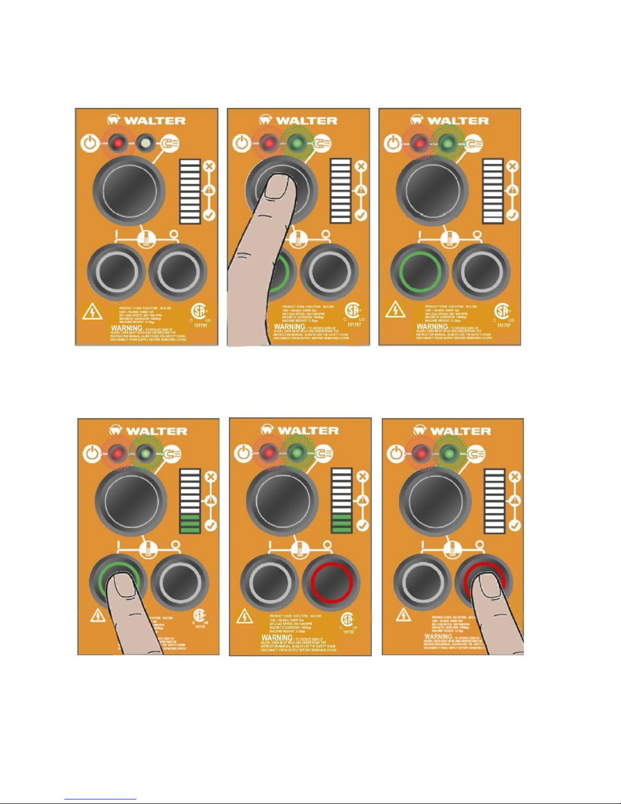
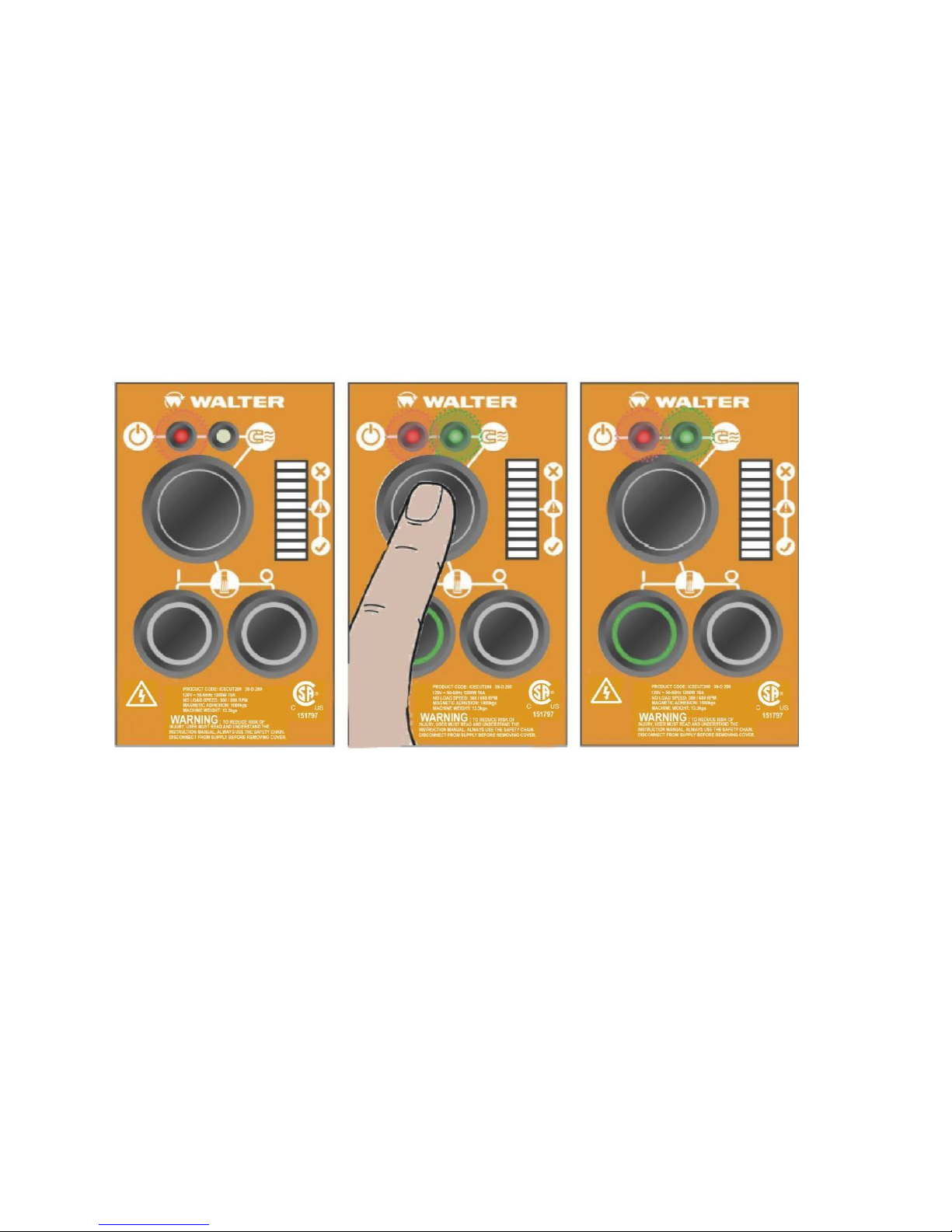
1) Power
When the drill is connected to
the power supply, the RED LED
will indicate power to the drill.
2) Magnet ON
To turn the magnet ON or OFF,
depress the large button on the
control panel. A GREEN LED will
indicate the magnet is ON.
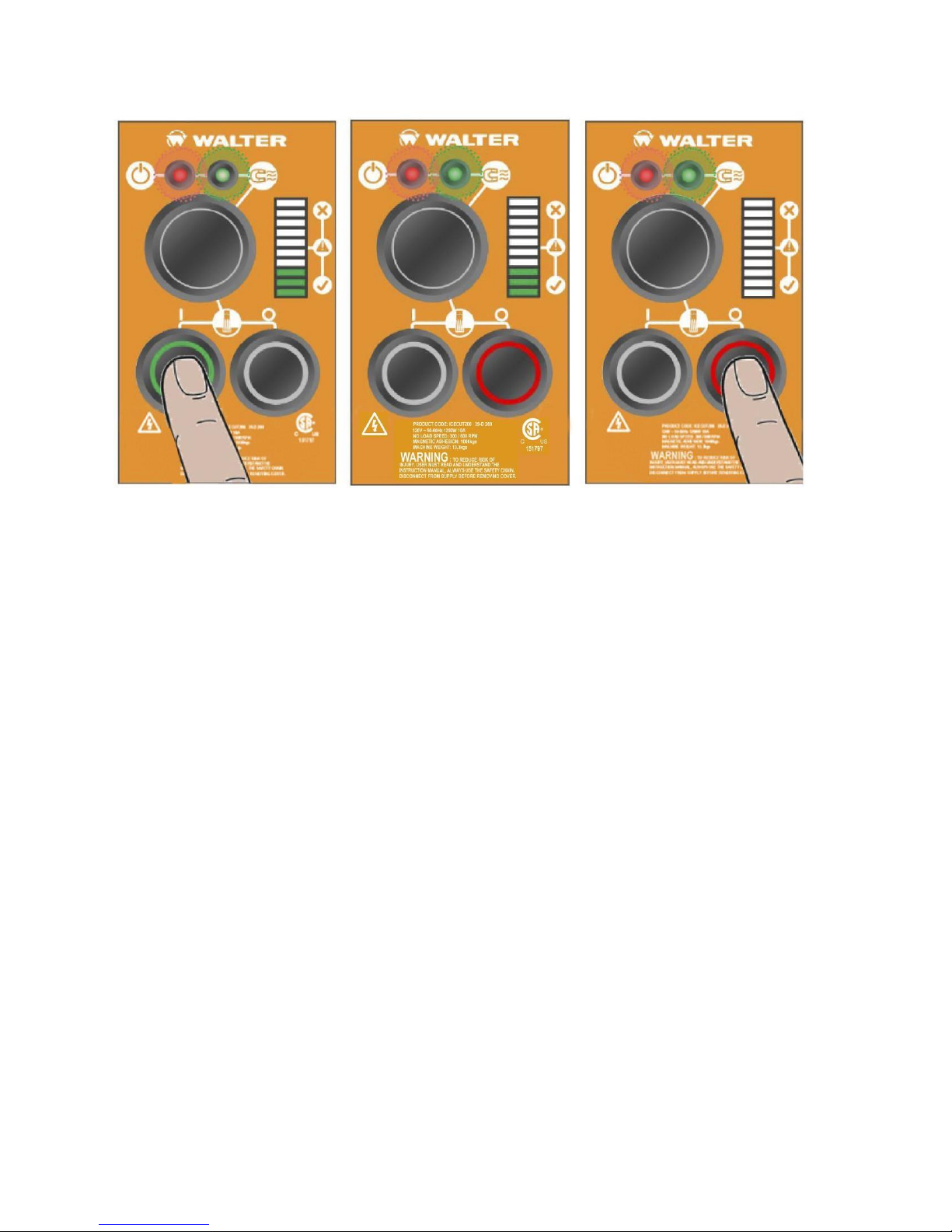
3) Motor switch
When the magnet has power
the GREEN switch will light up to
indicate motor start.
4) Motor ON
Press the GREEN Switch to turn
the motor on. Proceed with
cutting- following all safety
guidelines...
5) Annular cutting
See below for detailed description of
the control visual indicator
6) Motor OFF
To stop the motor press the RED
switch. The motor will stop and
the magnet will remain on. The
GREEN switch will turn on.
performance. It is available in 5 litres (53-C 056) and 20 litres (53-C 057).
7) CONTROL PANEL OPERATION
9
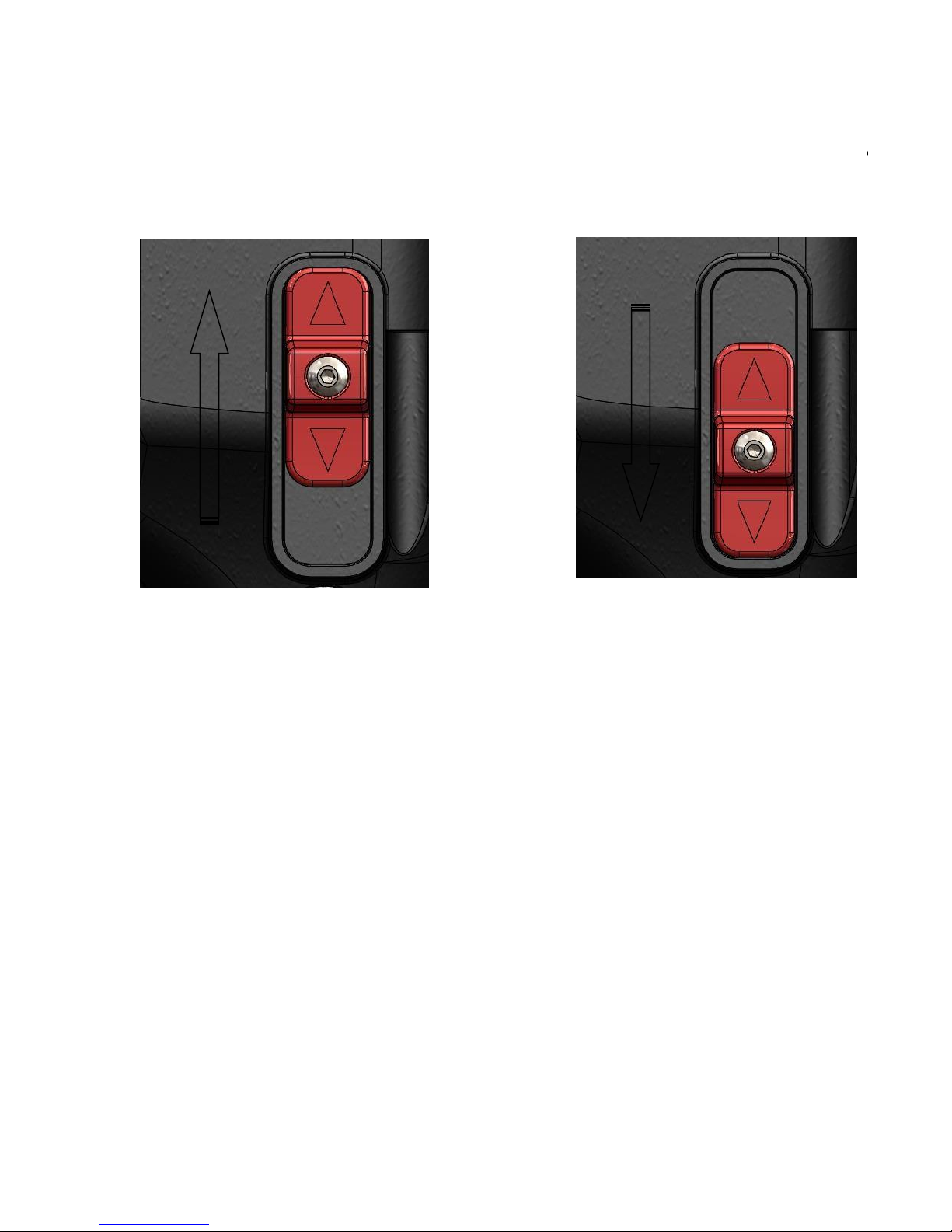
Gear position 1: High speed
, u p to 30mm diameter cutters
Gear position
2
: Low speed, from
30 to 40
mm diameter
cutters
8) GEAR SELECTION (ICECUT 200 only!)
The ICECUT200 magnetic drilling unit is fitted with a 2 speed gearbox. The gear is used to reduce the output speed
when using larger cutters.
Up to 30mm diameter cutters, gear position 1 should be used.
30 – 40mm diameter cutters, gear position 2 should be used.
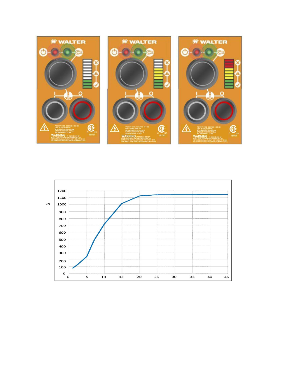
9) MAGNET DETECTION
It is advised that, when working on thin material, a packing piece should be used to increase the material thickness
under the magnet. Working on thin material without a packing piece will reduce the magnet holding force. It is
advised that the drill is to be operated on ferromagnetic material 8mm thick and above. Damage to the magnet base,
such as pitting, will affect the strength of the magnet holding force.
10) ACCUDRILL TECHNOLOGY
Designed for you, to get the most out of your machine and your annular core cutters. The ACCUDRILL Technology lest
you know thanks to an easy-to-read LED indicator when you are drilling with too much force, which will damage the
machine and the cutters. Allow the cutter to do the work and you will find that a much smoother hole and faster
drilling time is achieved.
10

Green Zone
Good! Try to keep the level in the
green zone for the best cutting and
optimum machine performance.
Yellow Zone
Indicates there is too much
pressure on the drill. Ease off to
get back to the green zone.
Red Zone
Overload: Back off immediately as
continuing to apply too much force will
cause the motor to cut off.
11
11) EXTENSION CABLE SELECTION
The machines are factory fitted with a 3 metre length of cable with conductors of 1.5mm² sections each:
LIVE, NEUTRAL and GROUND. If it becomes necessary to fit an extension cable from the power source, care must be
taken in using a cable of adequate capacity. Failure to do so will result in a loss of traction by the magnet and a
reduction of power from the motor.
Assuming the correct AC voltage conditions are used, it is recommended not to exceed the following extension lengths:
For 120V supply: 3.5metres of 3 core x 1.5mm²
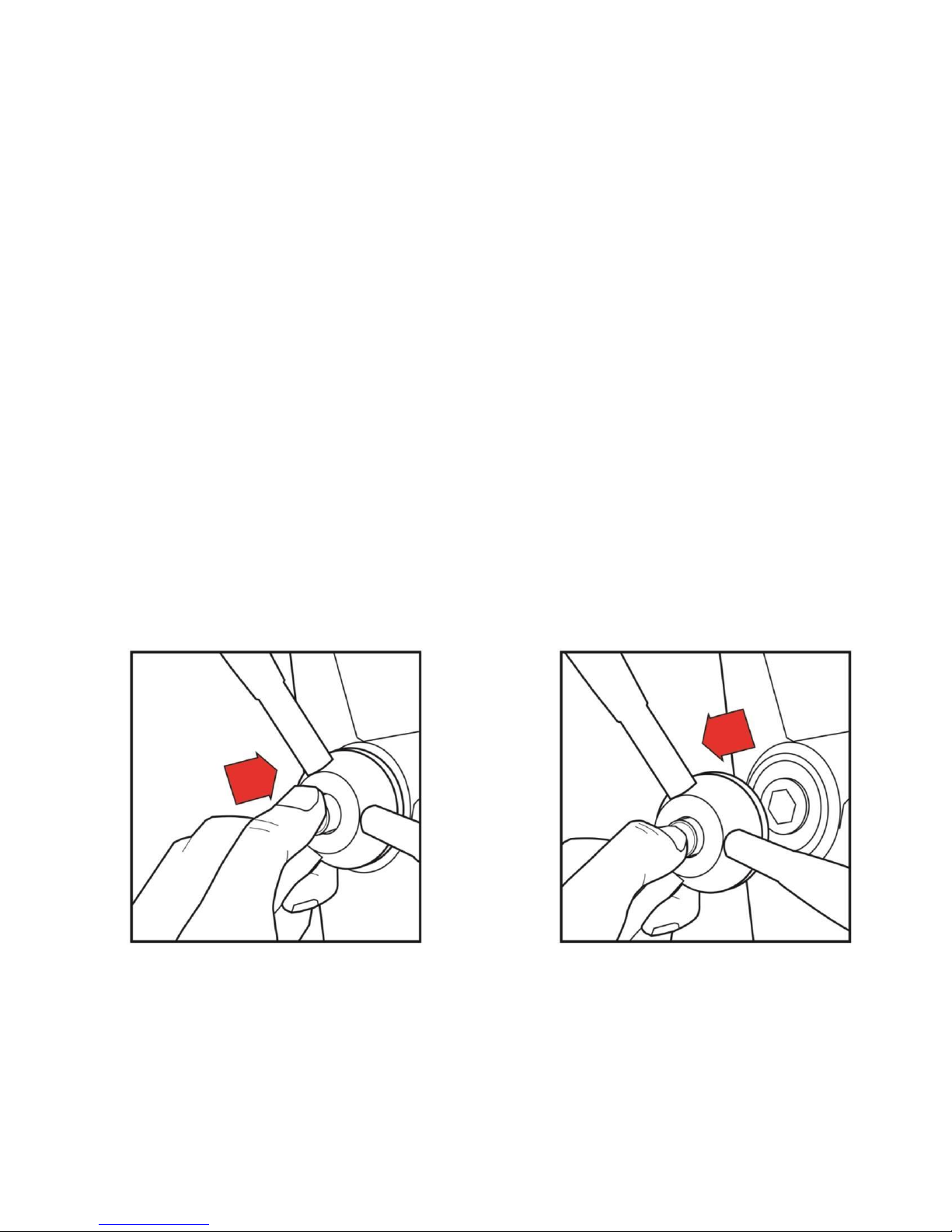
12) MOUNTING OF CUTTERS
ALWAYS DISCONNECT THE MACHINE FROM THE POWER SOURCE BEFORE CHANGING CUTTERS.
The machine has been made to accept cutters having 19.05mm (3/4”) dia. Weldon shanks. The following procedure
is to be used when mounting cutters:
Lay the machine on its side with feed handles uppermost; ensuring arbor is wound down to its lowest point to enable
access to socket screws.
Take appropriate pilot and place through the hole in cutter shank. Insert shank of cutter into bore of arbor, ensuring
alignment of two drive flats with socket screws.
Tighten both screws using hexagon key.
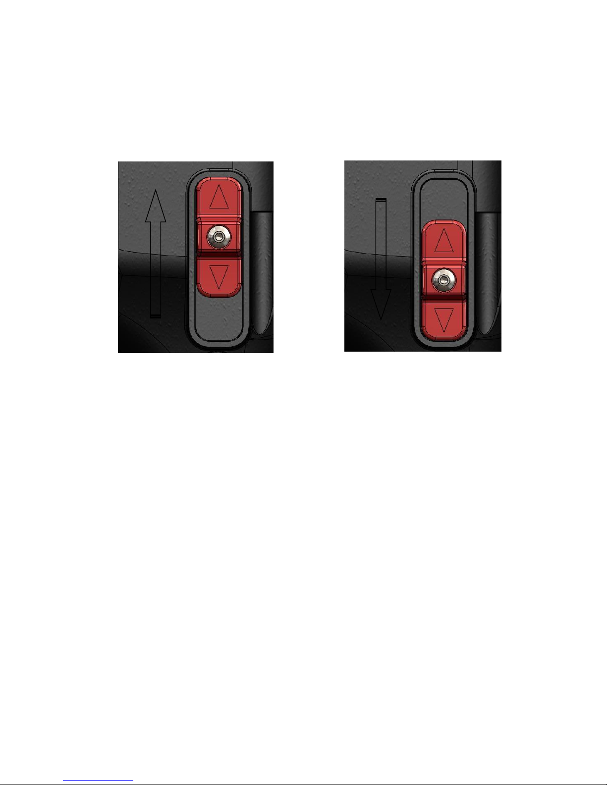
13) CAPSTAN OPERATION
The quick release capstan is a feature that offers the user a simple dual side operation.
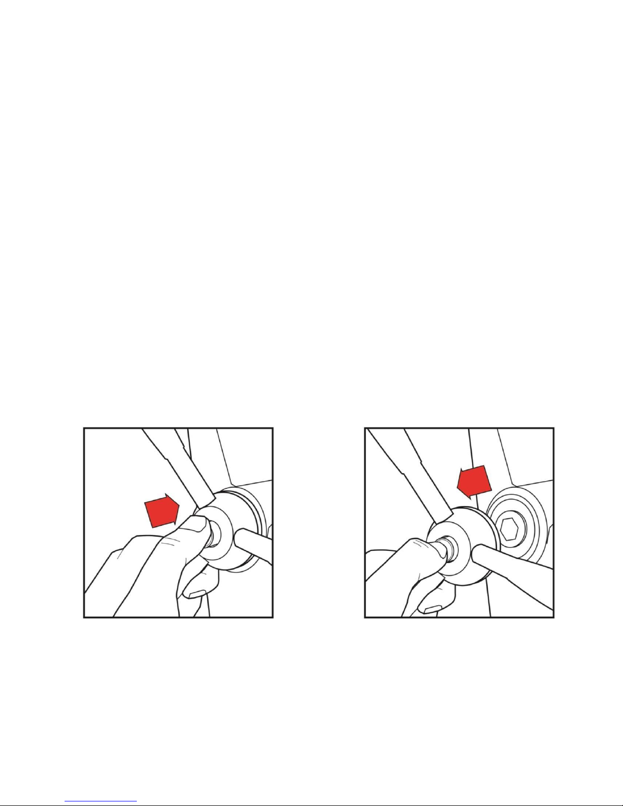
To remove the capstan, simply do the following:
1. Press in the central button on the capstan hub, holding onto the capstan arms.
2. With the button pressed in, pull the capstan away from the main body, holding on to the capstan arms.
3. Re-insert the hexagonal shaft into the hexagonal slot to attach the capstan.
12

14) MAIN OPERATING PROBLEMS AND REMEDIES
Problem
Cause
Remedy
1) Magnetic
base won’t
hold effectively
Material being cut may be too thin for efficient
holding.
Swarf or dirt under magnet.
Irregularity on magnet contact or work-piece.
Insufficient current going to magnet during
drilling cycles.
Attach an additional piece of metal under the
magnet, or mechanically clamp magnetic
base to work-piece. Clean magnet.
Use extreme care; file any imperfections flush
to surface.
Confirm power supply and output from control
unit, check supply cable.
2) Cutter skips
out of
centrepunch
mark at
initiation of cut
Magnetic base is not holding effectively.
Worn arbor bushing and/or ejector collar.
Too much feed pressure at start of cut.
Cutter is dull, worn, chipped or incorrectly
sharpened.
Poor centre-punch mark; weak pilot spring;
pilot not centred in centre-punch mark.
Worn or bent pilot, worn pilot hole.
Loose bolts on motor bushing support bracket,
main casting or loose gib adjusting set screws.
Loose bolts on motor bushing support bracket,
main casting or loose gib adjusting set screws.
See POINT 1) above.
New arbor bushing is needed.
Light pressure only is needed until a groove is
cut. The groove then serves as a stabilizer.
Replace or re-sharpen. Sharpening service is
available.
Improve centre-punch and/or replace worn
parts
Replace part or parts
Adjust where necessary
3) Excessive
drilling
pressure
required
Incorrectly re-sharpened, worn or chipped
cutter.
Coming down on swarf lying on surface of workpiece.
Gibs out of adjustment or lack of lubrication.
Swarf accumulated (packed) inside cutter.
Re-sharpen or replace.
Take care not to start a cut on swarf.
Adjust setscrews and lubricate.
Clear cutter.
4) Excessive
cutter breakage
Steel swarf or dirt under cutter.
Incorrectly re-sharpened or worn cutter.
Cutter skipping.
Slide needs adjustment.
Cutter not attached tightly to arbor.
Insufficient use of cutting oil or unsuitable type
of oil.
Incorrect speed
Remove cutter, clean part thoroughly and
replace.
Always have a new cutter on hand to refer to
for correct tooth geometry, together with
instruction sheet.
See POINT 2) above.
Tighten screws supporting the slide.
Retighten.
Inject oil of light viscosity into the
coolantinducing ring and check that oil is being
metered into cutter when pilot is depressed. If
not, check pilot groove and arbor internally for
dirt or apply oil externally. (Even a small
amount of oil is very effective).
Ensure correct gear is use for the cutter.
5) Excessive
cutter wear
Incorrectly re-sharpened cutter.
Insufficient or spasmodic cutting pressure.
Refer to instructions and a new cutter for
proper tooth geometry.
Use sufficient steady pressure to slow the drill
down. This will result in optimum cutting speed
and chip load.
13

15) FITTING THE CHUCK
Description
Every operation
1 week
1 Month
Visual check of machine for damage
X
Operation of machine
X
Check brush wear
X
Check magnetic base
X
Check alignment of the machine
X
Check grease
X
Check armature
X
To remove the arbor, lay the machine on its side.
Unscrew the two grub screws at the top of the arbor.
When the arbor has become detached from the spindle it can then be removed.
Remove the arbor support bracket and guard with the arbor retained.
Mount the chuck using the chuck adaptor.
Replace the chuck in the reverse sequence.
16) MAINTENANCE
In order to ‘get the best life’ out of your Walter machine always keep it in good working order.
A number of items must always be checked on Walter machines.
Before starting any job, always make sure the machine is in good working order and that there are no damaged or loose
parts.
Any loose parts must be tightened.
Before proceeding with any maintenance work, be certain that the power supply is disconnected.
Visually check the machine for damage.
The machine must be checked before operation for any signs of damage that will affect the operation of the machine.
Particular notice must be taken to the main cable. If the machine appears to be damaged it should not be used,
failure to do so may cause injury or death.
Check machine operation.
The Machine operation must be checked to ensure that all components are working correctly.
Machine Brushes
Should be checked to make sure there is no abnormal wear (this should be checked at least once a week if used
frequently). If the brush has worn more than 2/3 the original length, the brushes should be changed. Failure to do
so may cause damage to the machine.
Magnetic base
Before every operation, the magnetic base should be checked to make sure that the base is flat and there is no
damage present. An uneven magnet base will cause the magnet not to hold as efficiently and may cause injury to
the operator.
Adjustment of slide and bearing bracket alignment.
An essential requirement of the machine is that the slide can move in a smooth and controlled manner, free of lateral
movement and vibration.
14

This situation can be maintained by periodic adjustment of the slide and is accomplished in the following manner:
1. Place the machine in an upright position and, by means of the capstan, raise the slide to its highest position.
Clean the brass gib strips and apply a small amount of light machine oil to the wear surfaces.
2. Now lower the slide back to its lowest position. Bring the slide into the center of the dovetail slide housing
and loosen screws thus allowing free movement of the arbor support bracket.
3. Commencing with the middle screws, gently feed in all the screws until slight resistance is encountered.
4. Operate the slide up and down a few times to test the movement and make any further necessary
adjustments. Try to ensure that all the screws are exerting a uniform pressure on the slide from top to bottom.
A perfectly adjusted slide will operate freely up and down without any sideways movement.
5. Now raise the slide to its highest position. Slightly undo the arbor bearing bracket and, using fingers only,
tighten the screws.
6. Place the machine on a steel plate, connect to power supply and switch on the magnet. Start up the motor. If
the arbor is incorrectly aligned, the arbor support bracket will tend to oscillate. Make any necessary further
adjustments to the bracket to ensure correct alignment of the spindle and finally tighten the screws using a
spanner. Lastly, tighten the arbor bearing bracket.
Check machine grease.
The gearbox grease should be checked once a month to ensure all moving components are covered to prevent
wear. The grease should be changed at least once a year to ensure you achieve the best results from your machine.
Check machine armature.
This should be checked at least once a month to check that there are no visual signs of damage to the body or to
the commutator. Some signs of wear will be seen on the commutator over a period of time but this is normal (this
is the part that comes into contact with the brushes). However, if there are any signs of abnormal damage, the part
should be replaced.
15

17) TROUBLESHOOTING
Magnet and motor do not function
- The magnet switch is not connected to the power supply
- Damaged or defective wiring
- Defective fuse
- Defective magnet switch
- Defective control unit
- Defective power supply
Magnet does function, the motor does not
- Damaged or defective wiring
- Carbon brushes are stuck or worn out
- Defective magnet switch
- Defective on / off switch
- Defective control unit
- Defective armature and/or field
- Defective protective reed switch
Magnet does not function, but motor does
- Defective magnet
- Defective fuse
- Defective control unit
Hole cutters break quickly; holes are bigger than
the hole cutter
- Play in the guide
- Bent spindle
- Shaft extending from the motor is bent - Pilot bent
Motor running roughly and/or seizing up
- Bent spindle
- Shaft extending from the motor is bent
- Triangular guide not mounted straight
- Dirt between spindle and triangular guide
Motor making a rattling sound
- Gear ring (bottom of the armature) worn out
- Gear(s) worn out
- No grease in gear box
Motor humming, big sparks and motor has no
force
- Armature damaged
- Field burned
- Carbon brushes worn out
Motor does not start or fails.
- Damaged or defective wiring
- Damage to armature or field coil
- Damaged or defective brushes
Guiding takes a great deal of effort
- Guide is set too tight
- Guide is dry
- Guide/gear- rack/rotation system is dirty or damaged
Insufficient magnetic force
- Damaged or defective wiring
- Bottom of magnet not clean and dry
- Bottom of magnet not flat
- Work piece is not bare metal
- Work piece is not flat
- Work piece is too thin less than 10mm
- Defective control unit
- Defective magnet
Frame under voltage
- Damaged / defective wiring
- Defective magnet
- Motor seriously dirty
Fuse blows when magnet switch is turned on
- Damaged or defective wiring
- Wrong value fuse
- Defective magnet switch
- Defective control unit
- Defective magnet
Fuse blows when motor is started up
- Damaged or defective wiring
- Wrong value fuse
- Motor running roughly
- Defective armature and / or field
- Carbon brushes worn out
- Defective control unit
Rotation system free stroke too long
- Loose or defective gear-rack
- Defective rotation system
16

18) WARRANTY STATEMENT
Walter Surface Technologies Inc. Warrants its machines to be free from faulty materials, under normal usage of
machines, for a period of 12 months from initial date of purchase. All other parts (excluding cutters) are under
warranty for 90 days.
This Warranty does not cover:
1. Components that are subject to natural wear and tear caused by usage not in accordance with the operating
instructions.
2. Defects in the tool caused by non-compliance with the operating instructions, improper use, abnormal
environment conditions, inappropriate operating conditions, overload or insufficient servicing or maintenance.
3. Defects caused by using accessories, components or spare parts other than original Walter™ parts.
4. Tools to which changes or additions have been made.
5. Electrical components are subject to manufacturer’s warranty.
The warranty claim must be logged within the warranty period.
THIS WARRANTY IS IN LIEU OF ANY OTHER WARRANTY, (EXPRESSED OR IMPLIED) INCLUDING ANY WARRANTY
OF MERCHANTABILITY OR FITNESS FOR A PARTICULAR PURPOSE. WALTER™ RESERVES THE RIGHT TO MAKE
IMPROVEMENTS AND MODIFICATIONS TO DESIGN WITHOUT PRIOR NOTICE.
“ONLY THE BEST”
17

TABLE DES MATIÈRES FR
CONENTS OF TH Page
1) Utilisation 19
2) Instructions générales de sécurité 19
3) Symboles signalétiques 22
4) Spécifications 24
5) Procédures de fonctionnement sécuritaires 25
6) Mise en marche 25
7) Panneau de contrôle 26
8) Sélection des vitesses 28
9) Performance de l’aimant 28
10) Technologie ACCUDRILL 28
11) Rallonges électriques 30
12) Assemblage de fraises annulaires 30
13) Bouton-poussoir des poignées 30
14) Conseils concernant le perçage de trous 31
15) Fixation de l’adaptateur 32
16) Inspections routinières 32
17) Dépannage 34
18) Garantie 35
19) Índice - Espagñol 36
20) Índice - Português 54
21) Liste de Pièces de Rechanges 68
18

1) UTILISATION
L’utilsateur doit employer la perceuse magnétique afin de percer sur des métaux ferromagnétiques seulement.
L’aimant sert à garder l’unité de perçage en place durant son fonctionnement. Cette unite de perçage a été conçu
pour la fabrication, la construction, l’industrie ferroviaire, pétrochimique ainsi que tout autres applications
nécéssitant le perçage sur métaux ferreux. It is designed for use in fabrication, construction, railways, petrochemical
and any other applications when drilling ferrous metal.
Tout autre activité effectuée avec cet outil électrique ne sera pas couvert sous garanti.
2) INSTRUCTIONS GÉNÉRALES DE SÉCURITÉ
AVERTISSEMENT! Lire tous les avertissements de sécurité et toutes les instructions. Ne pas suivre les
avertissements et instructions peut donner lieu à un choc électrique, un incendie et/ou une blessure sérieuse.
CONSERVER TOUS LES AVERTISSEMENTS ET TOUTES LES INSTRUCTIONS POUR POUVOIR S’Y
REPORTER ULTÉRIEUREMENT.
SÉCURITÉ DE LA ZONE DE TRAVAIL
1. Conserver la zone de travail propre et blen eclalree. Les zones en desordre ou sombres sont propices aux
accidents.
2. Ne pas faire fonctionner les outils électriques en atmosphere explosive, par example en présence de liquides
Inflammables, de gaz ou de poussières. Les outils électriques produisent des étincelles qui peuvent enflammer
les poussiçres ou les fumées.
3. Maintenir les enfants et les personnes présentes à l'écart pendant l'utlllsatlon de l'outll. Les distractions
peuvent vous faire perdre le controle de l'outil.
SÉCURITÉ ELECTRIQUE
1. II faut que les fiches de l'outll électrlque soient adaptées au socie. Ne jamals modifier la fiche de quelque
façon que ce soit. Ne pas utlllser d'adaptateurs avec des outlls à branchement de terre. Des fiches non
modifiees et des socies adaptes réduiront le risque de choc électrique.
2. Eviter tout contact du corps avec des surfaces reliées à la terre telles que les tuyaux, les radiateurs, les
cuisinières et les réfrigérateurs. Il existe un risque accru de choc électrique si votre corps est relié a la terre.
3. Ne pas exposer les outils à la pluie ou à des conditions humides. La pénétration d'eau à l’intérieur d'un outiI
augmentera le risque de choc électrique.
4. Ne pas maltraiter le cordon. Ne jamals utillser le cordon pour porter, tirer ou débrancher l'outil. Maintenir le
cordon à l'écart de la chaleur, du lubrifiant, des arêtes ou des parties en mouvement. Des cordons
endommages ou emmêlés augmentent le risque de choc électrique.
5. Lorsqu'on utilise un outll à l'extérieur, utiliser un prolongateur adapté à l'utilisation extérieure. L'utilisation
d'un cordon adapté à l'utilisation extérieure réduit le risque de choc électrique.
6. Si l'usage d'un outil dans un emplacement humide est inévitable, utlilier une alimentation protégée par un
dispositif à courant différentiel residuel (RCD). L'usage d'un RCD reduit le risque de choc électrique.
SÉCURITÉ DES PERSONNES
1. Rester vigilant, regarder ce que vous êtes en train de faire et faire preuve de bon sens dans votre utilisation
de l'outil. Ne pas utiliser un outil lorsque vous êtes fatigué ou sous l'emprise de drogues, d'alcool ou de
médicaments. Un moment d'inattentlon en cours d'utilisation d'un outil peut entratiner des blessures graves
des personnes.
2. Utiliser un équiement de sécurité. Toujours porter une protection pour les yeux. Les équipements de sécurité
tels que les masques contre les poussieres, les chaussures de sécurité antidgrapantes, les casques ou les
protections acoustiques utilisées pour les conditions appropriées réduiront les blessures de personnes.
19

3. Eviter tout démarrage lntempestif. S'assurer que l'interrupteur est en position arrêt avant de brancher l'outll
au secteur et/ou au bloc de batteries, de le ramasser ou de le porter. Porter les outils en ayant le doigt sur
l’nterrupteur ou brancher des outils dont l'interrupteur est en position marche est source d'accidents.
4. Retirer toute clé de reglage avant de mettre l'outil en marche. Une clé laissée fixée sur une partie tournante
de l'outil peut donner lieu à des blessures de personnes.
5. Ne pas se précipiter. Garder une position et un équilibre adaptés à tout moment. Cela permet un meilleur
controle de l'outil dans des situations inattendues.
6. S'habiller de manière adaptée. Ne pas porter de vêtements amples ou de bijoux. Garder les cheveux, Jes
vêtements et les gants à distance des parties en mouvement. Des vêtements amples, des bijoux ou les
cheveux longs peuvent être pris dans des parties en mouvement.
7. Si des dispositifs sont fournis pour le raccordement d'équipements pour l'extractlon et la récupération des
poussières, s'assurer qu'ils sont connectés et correctement utilisés. Utiliser des collecleurs de poussière peut
réduire les risques dus aux poussières.
UTILISATION ET ENTRETIEN DE L’OUTIL
1. Ne pas forcer l'outll. Utlllser l'outll adapté à votre application. L'outil adapté realisera mieux le travail et de
maniere plus sûre au regime pour lequel il à été construit.
2. Ne pas utlllser l'outll si l'interrupteur ne permet pas de passer de l'état de marche à arrêt et vice versa. Tout
outi/ qui ne peut pas etre commande par l'interrupteur est dangereux et ii faut le reparer.Use clamps or
other practical way to secure and support the workpiece to a stable platform. Holding the work by hand or
against your body is unstable and may lead to loss of control.
3. Débrancher la fiche de la source d'alimentatlon en courant et/ou le bloc de batteries de l'outil avant tout
réglage, changement d'accessoires ou avant de ranger l'outll. De telles mesures de sécurité preventives
réduisent le risque de démarrage accidental de l'outil.
4. Conserver les outlls à l'arret hors de la portée des enfants et ne pas permettre à des personnes ne
connaissant pas l'outll ou les présentes instructions de le faire fonctionner. Les outils sont dangereux entre les
mains d'utilisateurs novices.
5. Observer la maintenance de l'outll. Vérifier qu'iI n'y a pas de mauvais alignement ou de blocage des parties
mobiles, des pièces cassées ou toute autre condition pouvant affecter le fonctionnement de l'outll. En cas de
dommages, faire réparer l'outil avant de l'utiliser. De nombreux accidents sont dus à des outils mal
entretenus.
6. Garder affûtés et propres les outlls permettant de couper. Des outils destinés à couper correctement
entretenus avec des pièces coupantes tranchantes sont moins susceptibles de bloquer et sont plus faciles à
contrôler.
7. Utiliser l'outil, les accessoires et les lames etc., conformement à ces instructions, en tenant compte des
conditions de travail et du travail à réaliser. L'utilisation de l'outil pour des opérations différentes de celles
prévues pourrait donner lieu à des situations dangereuses.
MAINTENANCE ET ENTRETIEN
1. Faire entretenlr l'outll par un réparateur qualifié utliisant uniquement des pièces de rechange identiques.
Cela assurera le maintien de la sécurité de l'outil.
AUTRE NOTES IMPORTANT SUR LE SECURITE
Coupez l’alimentation avant de procéder à tout réglage ou entretien de la perceuse.
1. Conservez l’aire de travail dégagée. Une aire encombrée augmente le risque de blessures.
2. Conditions à considérer :
• Protégez les outils de la pluie;
• Utilisez les outils dans des endroits secs;
• Assurez-vous de bien éclairer votre aire de travail (nous recommandons 500 lux.);
• Tenez tout liquide ou gaz inflammable à l’écart de vos outils;
• Assurez-vous d’avoir un accès facile à la prise de courant, à l’interrupteur principal et à ceux du moteur.
3. Prévention des décharges électriques :
20

Évitez le contact physique avec les surfaces reliées à la terre (par exemple : un tuyau, un radiateur, une cuisinière,
un réfrigérateur). La sécurité électrique peut être accrue en utilisant un dispositif à courant résiduel à grande
sensibilité (30 m A/0,1 s).
4. Gardez toute personne à l’écart de l’aire de travail! Ne laissez pas une personne non qualifiée, plus particulièrement
un enfant, toucher l’outil ou le câble de rallonge.
5. Rangez les outils dont vous ne vous servez pas dans un endroit sec, loin de la portée des enfants. Verrouillez-le.
6. Ne forcez pas la perceuse. Elle fonctionnera mieux et sera plus sécuritaire si vous l’utilisez convenablement.
7. Utilisez le bon outil :
• Utilisez des outils robustes pour effectuer des travaux importants;
• Utilisez cet outil seulement selon son utilisation prévue. Par exemple, n’utilisez pas la perceuse pour la coupe de
bois.
8. Portez des vêtements adéquats :
• Laissez les vêtements amples et les bijoux de côté, ils pourraient se prendre entre les pièces mobiles;
• Portez des chaussures à semelles antidérapantes lorsque vous travaillez à l’extérieur;
• Couvrez vos cheveux longs pour réduire le risque d’emmêlement.
9. Portez de l’équipement de protection lors de l’utilisation de cette perceuse :
• Portez des lunettes de protection pour protéger vos yeux des débris;
• Utilisez une protection auditive;
• Portez un masque durant les travaux de coupe pour vous protéger de la poussière;
• Portez des gants de protection pour protéger vos mains des débris et des copeaux.
10. Évitez de toucher les copeaux et de vous approcher de l’aire de coupe ou de la fraise lorsque la perceuse est en
marche.
11. Branchez un dispositif d’aspiration de poussière si possible. Assurez-vous qu’il soit bien utilisé et qu’il soit
correctement branché.
12. Prenez soin du câble : débranchez-le adéquatement de la fiche. Gardez-le à l’écart de toute source de chaleur, de
l’huile et des surfaces coupantes.
13. Immobilisez les pièces travaillées. Se servir de serre-joints ou d’un étau est plus sécuritaire que d’utiliser vos
mains.Soyez stable et gardez votre équilibre en tout temps. Ne déviez pas de votre posture!
14. Prenez soin de vos outils :
• Gardez les outils de coupe aiguisés et propres pour des performances accrues et pour assurer votre sécurité;
• Vérifiez régulièrement l’usure et tout dommage causé à la perceuse;
• Assurez-vous que la perceuse est propre et exempte de tout débris avant de l’utiliser;
• Coupez l’alimentation avant de procéder à l’entretien de la perceuse;
• Suivez les directives pour la lubrification et le changement d’accessoires;
• Inspectez le câble de la perceuse périodiquement afin de déceler tout dommage. Le cas échéant, adressez-vous à
un service d’entretien Walter Technologies pour surfaces inc. autorisé pour toute réparation;
• Inspectez les câbles de rallonge périodiquement et remplacez ceux qui sont endommagés;
• Gardez les poignées sèches, propres et exemptes d’huile ou de graisse.
15. Débranchez la perceuse lorsque vous ne l’utilisez pas, pendant l’entretien et lors du changement d’accessoires tels
que les fraises annulaires.
16. Prenez l’habitude de vérifier qu’aucune clé n’est à proximité de la perceuse avant de la démarrer.
17. Évitez de démarrer la perceuse involontairement. Assurez-vous que l’aimant n’est pas sous tension avant de brancher
la perceuse.
18. Utilisez des câbles de rallonge conçus pour l’extérieur lorsque vous y travaillez.
19. ATTENTION! Les vibrations émises par la perceuse en marche peuvent différer des valeurs de vibration données selon
la façon dont elle est utilisée.
20. Soyez alerte! Regardez ce que vous faites, utilisez votre jugement et n’utilisez pas la perceuse en cas de fatigue.
N’UTILISEZ PAS la perceuse si vous avez consommé de l’alcool ou TOUTE substance illégale.
21. Vérifiez qu’il ne manque aucune pièce avant d’utiliser la perceuse. Assurez-vous que toutes les pièces sont en bon
état. Le bon fonctionnement de la perceuse en dépend.
22. Attention! L’utilisation de tout accessoire non recommandée dans ce manuel d’utilisation peut représenter un risque
de blessure.
21

23. Faites réparer votre perceuse par un technicien qualifié Walter Technologies pour surfaces inc. Cet outil électrique est
conforme aux règles de sécurité pertinentes. Seules les personnes qualifiées, utilisant des pièces de rechange
originales, devraient exécuter les réparations. Autrement, la sécurité de l’utilisateur est compromise.
24. N’utilisez jamais cet outil si des pièces sont manquantes ou endommagées.
25. Ne projetez jamais d’eau ou de liquide inflammable sur la perceuse.
3) SYMBOLES SIGNALÉTIQUES
1 2 3 4
1. Référez-vous au manuel d’utilisation pour des questions opérationnelles ou de sécurité en lien avec cet outil.
2. Jetez l’outil et les composantes électriques à un endroit approprié.
3. Portez des lunettes de protection lorsque vous utilisez cet outil.
4. Portez une protection auditive lorsque vous utilisez cet outil.
22

4) SPÉCIFICATIONS
ICECUT 100
Tension / Fréquence
120V 50-60Hz
Pleine charge
7 A
850W
Électro-aimant
0.6A
69W
Dimensions
180mm de long 90mm
de large
Force magnétique à 20 °C pour un matériau de 25 mm d’épais
Épaisseur minimale de la tôle
Travailler sur une pièce plus mince que 25 mm réduira
progressivement les performances de l’aimant. Si possible,
ajoutez un autre matériau sous l’aimant ou à la pièce à
travailler pour arriver à une épaisseur adéquate. Dans le cas
contraire, la machine DOIT être stabilisée autrement.
10,000N
Charge totale (aimant + moteur)
919W
Dimensions globales
Hauteur — extension maximale
414mm
Hauteur minimum
349mm
Largeur (incluant le cabestan)
165mm
Longueur totale (incluant la garde)
270mm
Poids net
11.68kgs
39-D 100
Valeur totale des vibrations (somme vectorielle triaxiale) selon la
norme EN61029-1 :
Valeur d’émission vibratoire (ah):2.273m/s2
Incertitude: (K):1.5m/s²
Niveau de pression acoustique selon la norme EN61029-1 :
Pression acoustique :
87.9 dB(A)
Puissance acoustique (LwA): 100.9 dB(A)
Incertitude (K):3dB(A)
ICECUT 100
Capacité maximale de perçage : 30mm de diamètre x 35mm de profondeur Arbor
bore = 19.05mm (3/4") dia.
Vous devez porter une protection oculaire et auditive lorsque vous utilisez cet outil. Portez aussi des gants pour
protéger vos mains.
Cet outil, conçu au Royaume-Uni et fabriqué à l’étranger, est conforme aux exigences HD.400.1 et BS.2769/84 du CEC.
NE PAS ALIMENTER EN COURANT CONTINU.
N’utilisez pas votre perceuse magnétique sur la même structure que celle utilisée pour le
soudage à l’arc lorsque celui-ci est en cours.
Le courant continu peut rebondir vers l’aimant et causer des dommages irréparables.
ATTENTION : CET ENGIN DOIT ÊTRE MIS À LA TERRE!
NB : TOUTE MODIFICATION À CET ENGIN ENTRAÎNE L’ANNULATION DE LA
23

ICECUT 200
ICECUT200
Tension / Fréquence
120 V 50-60 Hz
Pleine charge
10 A
1200W
Électro-aimant
0.6A
69W
Dimensions
180mm de long 90mm
de large
Force magnétique à 20 °C pour un matériau de 25 mm d’épais
Épaisseur minimale de la tôle
Travailler sur une pièce plus mince que 25 mm réduira
progressivement les performances de l’aimant. Si possible,
ajoutez un autre matériau sous l’aimant ou à la pièce à
travailler pour arriver à une épaisseur adéquate. Dans le cas
contraire, la machine DOIT être stabilisée autrement.
10,000 N
Charge totale (aimant + moteur)
1269 W
Dimensions globales
Hauteur — extension maximale
514 mm
Hauteur minimum
434 mm
Largeur (incluant le cabestan)
185 mm
Longueur totale (incluant la garde)
285 mm
Poids net
13.3 kg
39-D 200
Valeur totale des vibrations (somme vectorielle triaxiale) selon la
norme EN61029-1 :
Valeur d’émission vibratoire (ah) : 2 746 m/s2
Incertitude (K) : 1,5 m/s²
Niveau de pression acoustique selon la norme EN61029-1 :
Pression acoustique (LpA) : 90,6 dB (A)
Puissance acoustique (LwA) : 103,6 dB (A)
Incertitude (K) : 3 dB (A)
Capacité maximale de perçage : 40 mm de diamètre x 50 mm de profondeur Alésage
de l’arbre = 19,05 mm (3/4 po) de diamètre.
Vous devez porter une protection oculaire et auditive lorsque vous utilisez cet outil. Portez aussi des gants pour
protéger vos mains.
Cet outil, conçu au Royaume-Uni et fabriqué à l’étranger, est conforme aux exigences HD.400.1 et BS.2769/84 du CEC.
NE PAS ALIMENTER EN COURANT CONTINU.
N’utilisez pas votre perceuse magnétique sur la même structure que celle utilisée pour le
soudage à l’arc lorsque celui-ci est en cours.
Le courant continu peut rebondir vers l’aimant et causer des dommages irréparables.
ATTENTION : CET ENGIN DOIT ÊTRE MIS À LA TERRE!
NB : TOUTE MODIFICATION À CET ENGIN ENTRAÎNE L’ANNULATION DE LA GARANTIE
24

5) PROCÉDURES DE FONCTIONNEMENT SÉCURITAIRES
À LIRE AVANT L’UTILISATION
Observez des mesures de sécurité générales lors de l’utilisation d’outils électriques afin de réduire les risques
d’incendie, de décharges électriques ou de blessures.
Assurez-vous que l’aimant n’est pas sous tension au moment de brancher l’outil.
N’utilisez pas cet outil dans un environnement mouillé ou humide. Dans le cas contraire, des blessures peuvent en
découler.
Utilisez cet outil loin de tout liquide ou gaz inflammable et loin de tout environnement à risque. Dans le cas contraire,
des blessures peuvent en découler.
Inspectez tous les câbles électriques, incluant les rallonges, et remplacez ceux endommagés AVANT de démarrer
l’outil. N’utilisez pas l’outil s’il semble endommagé.
Utilisez les câbles de rallonges adéquats aux conditions de travail.
Vérifiez toujours le bon fonctionnement de tous les systèmes, des interrupteurs, de l’aimant, etc. AVANT de démarrer
l’outil.
Assurez-vous de bien immobiliser l’outil sur une structure fixe indépendante AVANT de démarrer l’outil. Pour ce faire,
vous pouvez entre autres utiliser les sangles de retenue afin de réduire le risque de déplacement si l’aimant se
détache de la pièce à travailler. Dans le cas contraire, des blessures peuvent en découler.
Portez TOUJOURS une protection oculaire et auditive EPI approuvée et recommandée lorsque vous utilisez l’outil.
Débranchez l’outil de toute source d’alimentation avant de procéder à son entretien ou de changer la fraise.
Assurez-vous de TOUJOURS protéger vos mains adéquatement lorsque vous changez la fraise ou enlevez les copeaux,
car ceux-ci sont coupants. Au besoin, utilisez un outil ou une brosse pour les retirer de l’arbre.
Assurez-vous que les vis de retenue de la fraise sont TOUJOURS suffisamment serrées avant de démarrer l’outil.
Dégagez l’aire de travail des copeaux et de la saleté de façon régulière. Portez une attention particulière au-dessous
de la base magnétique.
Enlevez TOUJOURS votre cravate, vos bagues, votre montre et tout accessoire encombrant susceptibles de se prendre
dans la machinerie rotative avant d’utiliser l’outil.
Assurez-vous de TOUJOURS attacher les cheveux longs avant d’utiliser la perceuse.
Si la fraise se bloque dans la pièce à travailler, arrêtez le moteur immédiatement afin de prévenir les blessures.
Débranchez la machine de la source d’alimentation et effectuez un mouvement de va-et-vient avec l’arbre. NE TENTEZ
JAMAIS DE DÉGAGER LA FRAISE EN DÉMARRANT ET EN ARRÊTANT LE MOTEUR.
Si la perceuse tombe accidentellement, examinez-la attentivement afin de déceler tout dommage et vérifiez qu’elle
fonctionne convenablement AVANT de reprendre le perçage.
Inspectez régulièrement la perceuse et vérifiez qu’aucune pièce n’est endommagée ou desserrée.
Lorsque vous utilisez la perceuse en mode inversé, assurez-vous de TOUJOURS utiliser la quantité minimum de liquide
de refroidissement et que celui-ci ne pénètre pas dans l’unité motrice.
Les outils de coupe peuvent se briser. Assurez-vous de TOUJOURS placer le garde devant la fraise avant de démarrer la
perceuse. Dans le cas contraire, des blessures peuvent en découler.
Après avoir percé un trou, un lopin sera éjecté. Ne faites pas fonctionner la perceuse, le lopin pourrait causer des
blessures.
Rangez TOUJOURS la machine dans un endroit sûr lorsqu’elle n’est pas utilisée.
Assurez-vous que SEULS des techniciens WALTER TECHNOLOGIES POUR SURFACES INC. effectuent les réparations
nécessaires.
6) MISE EN MARCHE
Assurez-vous qu’il n’y a pas de copeaux dans la fraise. Cela pourrait réduire la profondeur de la coupe.
Assurez-vous de disposer de la quantité d’huile de coupe suffisante pour le travail à accomplir. Remplissez votre
bouteille au besoin.
Appuyez sur le pilote de temps à autre pour vérifier que l’huile de coupe est correctement dosée.
Pour mettre la perceuse en marche, suivez les directives du tableau de contrôle.
Pour éteindre le moteur, appuyer TOUJOURS sur le bouton d’arrêt rouge. N’ÉTEIGNEZ PAS le moteur en appuyant sur
l’interrupteur de l’aimant.
Pour commencer à percer, appliquez une légère pression jusqu’à ce que la fraise pénètre la surface de travail.
Augmentez la pression pour charger le moteur. Évitez d’appliquer une trop grande pression; ceci n’accélèrera pas le
perçage et le mécanisme de prévention de surcharge fera arrêter le moteur (celui-ci peut être redémarré en
enfonçant le bouton de démarrage du moteur). Cela peut aussi causer une surchauffe pouvant compromettre
25
l’éjection normale du lopin.
Assurez-vous d’avoir retiré le lopin résultant du trou précédent avant de percer à nouveau.
Si un lopin se coince dans la fraise, placez la machine sur une surface plane, mettez l’aimant sous tension et abaissez
délicatement la fraise jusqu’à ce qu’elle entre en contact avec la surface. Cette action devrait permettre de redresser
le lopin et de l’éjecter.
Appliquez une petite quantité d’huile de graissage légère régulièrement sur le roulement de support de la glissière et
de l’arbre.
Le bris de fraise est normalement occasionné par un ancrage inadéquat, une glissière mal ajustée ou un roulement de
support de l’arbre usé (voir les directives d’entretien).
N’utilisez que l’huile de coupe recommandée. L’huile de coupe ICECUT de Walter Technologies pour surfaces inc. est
spécialement formulée pour optimiser les performances de la fraise. Elle est offerte en quantité de 5 litres (53-C 056)
ou de 20 litres (53-C 057).
7) PANNEAU DE CONTRÔLE
1) Tension Lorsque la
perceuse est branchée à une
source d’alimentation, le voyant
lumineux rouge
2) Tension de l’aimant
Enfoncez le grand bouton pour
mettre l’aimant sous tension ou
l’éteindre. Le voyant lumineux vert
s’illumine lorsqu’il est sous
26
tension. 3) Interrupteur du
moteur Lorsque l’aimant est sous
tension, l’interrupteur vert
s’illumine pour indiquer comment
démarrer le moteur.
4) Démarrer le moteur 5) Perçage
Enfoncez l’interrupteur vert pour Voir la description détaillée des
démarrer le moteur. Commencez indicateurs de niveau ACCUDRILL cià
percer en suivant toutes les dessous. consignes de sécurité.
6) Éteindre le moteur Enfoncez
l’interrupteur rouge pour éteindre
le moteur. Celui-ci s’arrête, mais
l’aimant reste sous tension.
L’interrupteur vert s’illumine.
27
8) SÉLECTION DES VITESSES (ICECUT200 seulement)
La perceuse magnétique Icecut 200 est dotée d’une boîte à deux vitesses. Elle sert à réduire la vitesse de sortie lorsque la perceuse est utilisée
avec une fraise de plus grand diamètre.
Utilisez la 1re vitesse pour une fraise dont le diamètre est plus petit que 30 mm. Utilisez la 2e vitesse pour une
fraise dont le diamètre varie entre 30 et 40 mm.
Position 1 : grande vitesse
Pour une fraise d’un diamètre inférieur à
30 mm.
Position 2 : basse vitesse
Pour une fraise d’un diamètre variant
entre 30 et 40 mm.
9) PERFORMANCE DE L’AIMANT
Lorsque vous travaillez sur une pièce mince, il est recommandé d’utiliser une cale pour augmenter l’épaisseur du
matériau sous l’aimant. Si vous omettez de le faire, la force magnétique de l’aimant sera réduite.
Il est conseillé d’utiliser la perceuse sur des matériaux ferromagnétique de plus de 8 mm d’épaisseur. Des
dommages à la base magnétique, comme la corrosion, entraînent une baisse de la force magnétique de l’aimant.
10) Technologie ACCUDRILL
Conçus pour vous permettre de tirer le meilleur de la perceuse et de vos fraises, les indicateurs de niveau la
technologie ACCUDRILL sont faciles à lire. Lors du perçage, ils indiquent par un témoin LED quand la pression
appliquée risque d’endommager votre équipement. Laissez la fraise faire le travail et vous constaterez à quel point
le perçage est facile et rapide.
28
Zone verte
FORCE MAGNÉTIQUE
Épaisseur du matériau en mm
Bon! Tentez de rester dans cette
zone pour une coupe impeccable
et un rendement optimal.
Zone jaune
Indique que vous appliquez trop de
pression. Relâchez légèrement
pour retourner dans la zone verte.
Zone rouge
Surcharge : relâchez immédiatement. La
machine s’arrêtera si vous continuez
d’appliquer une trop grande pression.
29
11) RALLONGES ÉLECTRIQUES
La perceuse est offerte avec un câble de trois mètres de long. Ce câble est composé de trois âmes de 1,5 mm² : la
PHASE, le NEUTRE et la TERRE. Si vous avez besoin d’ajouter un câble de rallonge au câble d’alimentation,
assurezvous qu’il soit adéquat. Dans le cas contraire, la force de l’aimant et la puissance du moteur seront
réduites.
La perceuse doit être alimentée en courant alternatif d’une tension appropriée. Il est recommandé d’utiliser des
rallonges dont la longueur n’excède pas les mesures suivantes : Alimentation de 110 V : 3,5 mètres de câble à
trois fils x 1,5 mm²
12) ASSEMBLAGE DE FRAISES ANNULAIRES
DÉBRANCHEZ TOUJOURS LA PERCEUSE DE LA SOURCE D’ALIMENTATION AVANT DE PROCÉDER AU
CHANGEMENT DE LA FRAISE.
• La perceuse est conçue pour recevoir une fraise de 19,05 mm (3/4 po) de diamètre (tige Weldon). Suivez les
directives suivantes pour installer la fraise.
• Couchez la perceuse sur le côté, avec les poignées vers le haut, et assurez-vous que l’arbre soit abaissé au plus
bas afin d’avoir accès aux vis creuses RD4066.
• Prenez le pilote adéquat et placez-le dans l’emplacement désigné pour recevoir la tige de la fraise. Insérez la
tige de la fraise dans l’alésage de l’arbre en vous assurant que les deux côtés plats soient alignés sur les vises
creuses.
• Serrez les deux vis à l’aide de la clé hexagonale.
13) BOUTON-POUSSOIR DES POIGNÉES
Le cabestan à relâchement rapide peut facilement être retiré en deux étapes faciles :
1. Enfoncez le bouton central du moyeu du cabestan en tenant les bras de celui-ci.
2. Tout en gardant le bouton enfoncé, retirez le cabestan de la pièce principale en tenant les bras de celui-ci.
3. Réinsérez l’arbre hexagonal dans la fente hexagonale pour fixer le cabestan.
30
 Loading...