

Walter BIG BUFF III, 6265 C User Manual
USER GUIDE
GUIDE DE L’UTILISATEUR
MANUAL DEL USUARIO
MANUAL DO PROPRIETÁRIO
BIG BUFF III
(6265 C)
CIRCULAR FINISHING SYSTEM
POLISSEUSE / PONÇEUSE
SISTEMA CIRCULAR DE TERMINACION
SISTEMA DE ACABAMENTO CIRCULAR
BIG BUFF III
CIRCULAR FINISHING SYSTEM
(Model 6265 C)
ENGLISH
E N GLI S H
BIG BUFF III
CIRCULAR FINISHING SYSTEM
(Model 6265 C)

1
Thank you for purchasing the BIG BUFF III
CIRCULAR FINISHING SYSTEM (Model 6265 C)
This operating instruction booklet has been designed to give
you all the information on the BIG BUFF III.
To ensure perfect functioning of your circular finishing
system, carefully read these instructions before using the
tool. Familiarize yourself with this tool's operation, its
particular features, applications and limitations. You will
also find useful tips on safety and maintenance.
TITLES PAGES
General Safety Rules ...................................................................................2
Introduction .................................................................................................8
Voltage .........................................................................................................
9
Extension cord .............................................................................................9
Technical Data .............................................................................................
9
Model illustration ........................................................................................10
Side handle ..................................................................................................10
Spindle lock .................................................................................................10
Switch ..........................................................................................................10
Dialspeed TM selector .................................................................................11
Dialspeed TM settings .................................................................................11
Dynamax TM Electronics ............................................................................11
Operation .....................................................................................................12
High Productivity Abrasives ........................................................................
12
Carbon Brushes ............................................................................................15
Preventive Maintenance ..............................................................................15
Warranty Policy ...........................................................................................
16
WALTER Sales and Service ........................................................................
17

2
3
General safety rules
Every WALTER power tool is produced in accordance with applicable
standards governing the manufacture, performance and safety of power
tools.
WARNING – To reduce the risk of injury, user must read instruction manual.
Read all instructions. Failure to follow all instructions listed below may
result in electric shock, fire and/or serious injury. The term “power tool”in
all of the warnings listed below refers to your mains-operated (corded)
power tool or battery-operated (cordless) power tool.
SAVE THESE INSTRUCTIONS
1) Work area safety
a) Keep work area clean and well lit
. Cluttered or dark areas invite
accidents.
b) Do not operate power tools in explosive atmospheres, such as
in the presence of flammable liquids, gases or dust
. Power tools
create sparks which may ignite the dust or fumes.
c) Keep children and bystanders away while operating a power
tool. Distractions can cause you to lose control
2) Electrical safety
a) Power tool plugs must match the outlet. Never modify the plug in
any way.
Do not use any adapter plugs with earthed (grounded) power
tools.
Unmodified plugs and matching outlets will reduce risk of electric
shock.
b) Avoid body contact with earthed or grounded surfaces such as
pipes, radiators, ranges and refrigerators. There is an increased
risk of electric shock if your body is earthed or grounded.
c) Do not expose power tools to rain or wet conditions. Water
entering a power tool will increase the risk of electric shock.
d) Do not abuse the cord. Never use the cord for carrying, pulling
or unplugging the power tool. Keep cord away from heat, oil,
sharp edges or moving parts
. Damaged or entangled cords increase
the risk of electric shock.
e) When operating a power tool outdoors, use an extension cord
suitable for outdoor use
. Use of a cord suitable for outdoor use
reduces the risk of electric shock.
3) Personal safety
a) Stay alert, watch what you are doing and use common sense
when operating a power tool. Do not use a power tool while you
are tired or under the influence of drugs, alcohol or medication.
A moment of inattention while operating power tools may result in
serious personal injury.
b) Use safety equipment. Always wear eye protection. Safety
equipment such as dust mask, non-skid safety shoes, hard hat,
or hearing protection used for appropriate conditions will reduce
personal injuries.
c) Avoid accidental starting. Ensure the switch is in the off-position
before plugging in. Carrying power tools with your finger on the
switch or plugging in power tools that have the switch on invites
accidents.
d) Remove any adjusting key or wrench before turning the power
tool on.
A wrench or a key left attached to a rotating part of the power tool
may result in personal injury.
e) Do not over-reach. Keep proper footing and balance at all
times. This enables better control of the power tool in unexpected
situations.
f) Dress properly. Do not wear loose clothing or jewellery. Keep
your hair, clothing and gloves away from moving parts. Loose
clothes, jewellery or long hair can be caught in moving parts.
g) If devices are provided for the connection of dust extraction and
collection facilities, ensure these are connected and properly
used. Use of these devices can reduce dust-related hazards.

4
5
Operation of this power tool
a) This power tool is intended to function as a sander, wire brush,
or polisher. Read all safety warnings, instructions, illustrations
and specifications provided with this power tool. Failure to follow
all instructions listed below may result in electric shock, fire and/or
serious injury.
b) Operations such as grinding or cutting-off are not recommended
to be performed with this power tool. Operations for which the
power tool was not designed may create a hazard and cause personal
injury.
c) Do not use accessories which are not specifically designed
and recommended by Walter. Just because the accessory can be
attached to your power tool, it does not assure safe operation.
d) The rated speed of the accessory must be at least equal to the
maximum speed marked on the power tool. Accessories running
faster than their RATED SPEED can break and fly apart.
e) The outside diameter and the thickness of your accessory must
be within the capacity rating of your power tool. Incorrectly sized
accessories cannot be adequately guarded or controlled.
f) The arbour size of wheels, flanges, backing pads or any other
accessory must properly fit the spindle of the power tool.
Accessories with arbour holes that do not match the mounting
hardware of the power tool will run out of balance, vibrate
excessively and may cause loss of control.
g) Do not use a damaged accessory. Before each use inspect the
accessory such as abrasive wheels for chips and cracks, backing
pad for cracks, tear or excess wear, wire brush for loose or
cracked wires. If power tool or accessory is dropped, inspect for
damage or install an undamaged accessory. After inspecting and
installing an accessory, position yourself and bystanders away
from the plane of the rotating accessory and run the power tool
at maximum no-load speed for one minute. Damaged accessories
will normally break apart during this test time.
h) Wear personal protective equipment. Depending on application,
use face shield, safety goggles or safety glasses. As appropriate,
wear dust mask, hearing protectors, gloves and workshop apron
4) Power tool use and care
a) Do not force the power tool. Use the correct power tool for your
application. The correct power tool will do the job better and safer
at the rate for which it was designed.
b) Do not use the power tool if the switch does not turn it on and
off. Any power tool that cannot be controlled with the switch is
dangerous and must be repaired.
c) Disconnect the plug from the power source and/or the battery
pack from the power tool before making any adjustments,
changing accessories, or storing power tools. Such preventive
safety measures reduce the risk of starting the power tool
accidentally.
d) Store idle power tools out of the reach of children and do
not allow persons unfamiliar with the power tool or these
instructions to operate the power tool. Power tools are dangerous
in the hands of untrained users.
e) Maintain power tools. Check for misalignment or binding of
moving parts, breakage of parts and any other condition that
may affect the power tool’s operation. If damaged, have the
power tool repaired before use. Many accidents are caused by
poorly maintained power tools.
f) Keep cutting tools sharp and clean. Properly maintained cutting
tools with sharp cutting edges are less likely to bind and are easier to
control.
g) Use the power tool, accessories and tool bits etc., in accordance
with these instructions and in the manner intended for the
particular type of power tool, taking into account the working
conditions and the work to be performed. Use of the power
tool for operations different from those intended could result in a
hazardous situation.
5) Service
a) Have your power tool serviced by a qualified repair person using
only identical replacement parts. This will ensure that the safety of
the power tool is maintained.

6
7
Further safety instructions for all operations
Kickback and Related Warnings
Kickback is a sudden reaction to a pinched or snagged rotating wheel,
backing pad, brush or any other accessory. Pinching or snagging
causes rapid stalling of the rotating accessory which in turn causes the
uncontrolled power tool to be forced in the direction opposite of the
accessory’s rotation at the point of the binding.
For example, if an abrasive wheel is snagged or pinched by the work
piece, the edge of the wheel that is entering into the pinch point can dig
into the surface of the material causing the wheel to climb out or kick out.
The wheel may either jump toward or away from the operator, depending
on direction of the wheel’s movement at the point of pinching. Abrasive
wheels may also break under these conditions. Kickback is the result of
power tool misuse and/or incorrect operating procedures or conditions and
can be avoided by taking proper precautions as given below.
a) Maintain a firm grip on the power tool and position your
body and arm to allow you to resist kickback forces. Always
use auxiliary handle, if provided, for maximum control over
kickback or torque reaction during start-up. The operator can
control torque reactions or kickback forces, if proper precautions are
taken.
b) Never place your hand near the rotating accessory. Accessory
may kickback over your hand.
c) Do not position your body in the area where power tool will
move if kickback occurs. Kickback will propel the tool in direction
opposite to the wheel’s movement at the point of snagging.
d) Use special care when working corners, sharp edges etc. Avoid
bouncing and snagging the accessory. Corners, sharp edges or
bouncing have a tendency to snag the rotating accessory and cause
loss of control or kickback.
e) Do not attach a saw chain woodcarving blade or toothed saw
blade.
Such blades create frequent kickback and loss of control.
capable of stopping small abrasive or work piece fragments. The
eye protection must be capable of stopping flying debris generated by
various operations. The dust mask or respirator must be capable of
filtrating particles generated by your operation. Prolonged exposure
to high intensity noise may cause hearing loss.
i) Keep bystanders a safe distance away from work area.
Anyone entering the work area must wear personal protective
equipment. Fragments of work piece or of a broken accessory may
fly away and cause injury beyond immediate area of operation.
j) Hold power tool by insulated gripping surfaces only, when
performing an operation where the cutting accessory may
contact hidden wiring or its own cord. Cutting accessory
contacting a “live”wire may make exposed metal parts of the power
tool “live” and shock the operator.
k) Position the cord clear of the spinning accessory. If you lose
control, the cord may be cut or snagged and your hand or arm may
be pulled into the spinning accessory.
l) Never lay the power tool down until the accessory has come to
a complete stop. The spinning accessory may grab the surface and
pull the power tool out of your control.
m) Do not run the power tool while carrying it at your side.
Accidental contact with the spinning accessory could snag your
clothing, pulling the accessory into your body.
n) Regularly clean the power tool’s air vents. The motor’s fan will
draw the dust inside the housing and excessive accumulation of
powdered metal may cause electrical hazards.
o) Do not operate the power tool near flammable materials. Sparks
could ignite these materials.
p) Do not use accessories that require liquid coolants. Using water
or other liquid coolants may result in electrocution or shock.
8
9
VOLTAGE
Before connecting the tool, make sure that the voltage shown on the rating
plate is the same as the power source.
Operating the tool on a voltage other than specified on its rating plate, may
result in personal injury to the user and damage to the unit.
EXTENSION CORD
When an extension cord is required, use one that is sufficient for the power
requirement of the tool. Extension cords of inadequate wire size cause a
serious drop in voltage, loss of power and possible motor damage. To limit
line voltage drop to a safe level, refer to the following table:
Length in meters 8 15 23 30
Length in feet 25 50 75 100
Wire size AWG
14 14 12 10
NOTE: Extension cords that are used outdoors must be approved for outdoor use.
TECHNICAL DATA
MODEL 6265 C
Voltage .........................120 V AC; 60 Hz
Amperage .....................12
No-load speed ..............POS.A POS.B POS.C POS.D POS.E POS.F POS.G
.....................................2,000 2,800 3,800 4,700 5,400 6,400 7,300
Spindle Thread ............. 5/8“ -11 NC
Weight .........................2,66kg - 5lb. 14oz
MODEL 6265 C
Voltage .........................220 - 240 V AC; 50 - 60 Hz
Amperage .....................7,2
No-load speed ..............POS.A POS.B POS.C POS.D POS.E POS.F POS.G
.....................................2,000 2,800 3,800 4,700 5,400 6,400 7,300
Spindle Thread ............. M14
Weight ..........................2,66kg - 5lb. 14oz
Safety Warnings Specific for Sanding Operations:
a) Do not use excessively oversized sanding disc paper. Follow
manufacturers recommendations, when selecting sanding paper.
Larger sanding paper extending beyond the sanding pad presents
a laceration hazard and may cause snagging, tearing of the disc or
kickback.
Safety Warnings Specific for Polishing Operations:
a) Do not allow any loose portion of the polishing bonnet or its
attachment strings to spin freely. Tuck away or trim any loose
attachment strings. Loose and spinning attachment strings can
entangle your fingers or snag on the work piece.
INTRODUCTION
Your WALTER power tool is precision built to meet the highest industrial
standards. For maximum performance and longest tool life, follow the
operating instructions and service procedures outlined in this manual.
This tool is CSA certified.
This tool is double insulated, it does not have to be grounded.
It may be safely operated from a grounded or ungrounded
receptacle. It is supplied with a 2-conductor power cord and
a polarized plug (one blade wider than the other). The plug
will fit only one way into a polarized outlet. If the plug does
not fit, have the outlet replaced by a qualified electrician. If an
extension cord is necessary, only one that is polarized must be
used. Do not change the plug in any way.
In order to maintain the safety features of the double insulation, the
housing must not be drilled to affix nameplates or the like. Self-adhesive
labels may be used for this purpose.
10
11
DIALSPEED™ SELECTOR
Select the required speed by rotating speed selector (4). Positions A-G
roughly equal the following no load revolutions per minute:
Pos. A B C D E F G
RPM 2,000 2,800 3,800 4,700 5,400 6,400 7,300
DIALSPEED™ SETTINGS
Set speed selector (4) to position D, and adjust either up or down until you
have found a speed that meets your surface finishing requirements.
The correct setting will depend on:
a) Type of material being worked
c) Amount of pressure being applied
b) Abrasive accessory being used
d) Surface finish required
DYNAMAX™ ELECTRONICS
The built-in electronic feedback circuit continuously monitors the load on
the motor and adjusts power as required to maintain a virtually constant
speed.
Should the machine be subjected to overload for an extended period, for
example when being run at a lower speed setting, the rotation speed will
be decreased electronically to protect the motor. Rather than stopping
completely, the machine will continue to run slowly to allow the motor to
cool. After a brief period, by switching the machine off and on again, it can
then be used again at the rated load.
When used for extended periods, it is quite normal for the machine to
become quite warm, with the thermal overload protection, as described
above, cutting in whenever necessary. With practice, the user will feel to
what extent the machine can be loaded at each speed setting for continuous
uninterrupted operation.)
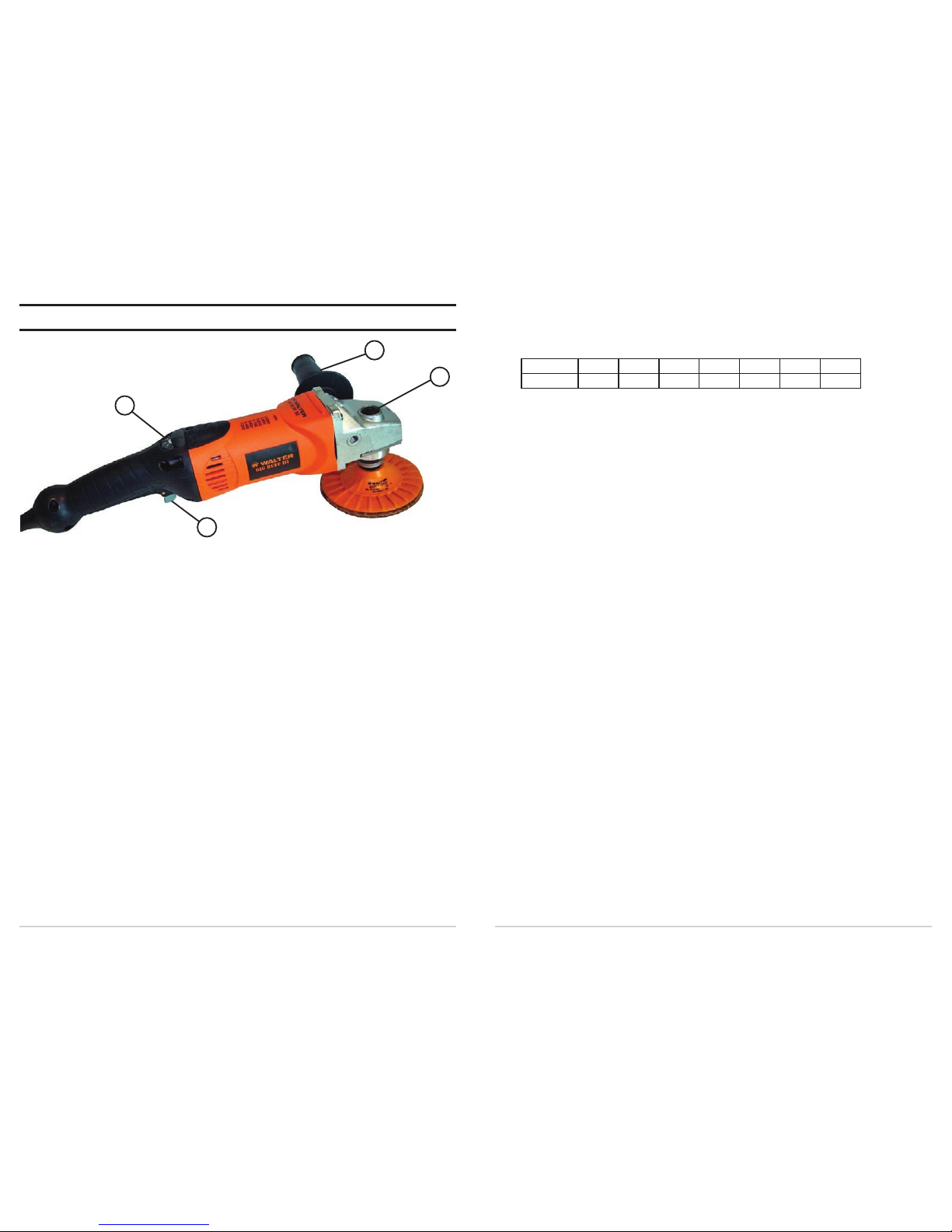
MODEL ILLUSTRATION
3
2
4
1
SIDE HANDLE
Side handle (1) may be mounted on either side of the gear housing for
greater convenience in both right and left hand operation. For reasons of
safety and better control, the side handle must always be used.
SPINDLE LOCK
To mount or remove abrasive wheels and accessories, disconnect the
machine from the power supply. Depress spindle lock button (2), while
rotating the spindle by hand until the locking mechanism is engaged. With
the spindle in a locked position, use the appropriate pin key or open-end
spanner for the accessory being utilized. Never depress the locking button
while the tool is turned on.
SWITCH
To start, push locking switch (3) forward, locking it in the ON position.
To stop, press up on the long part of the switch, returning it to the OFF
position.

12
13
BLENDEX
Surface Conditioning Discs
-Grid line conditioning
4 1/2” 5”
-Cleaning and deburring
Coarse tan
07-R 452 Coarse tan 07-R 452
-Oxidation removal Medium Medium 07-R 452
-Paint dulling and stripping
maroon
07-R 453 maroon 07-R 452
Fine blue
07-R 454
-Hiding imperfections
-Produce textured finishes
6” 7”
Coarse tan
07-R 602
Coarse tan
07-R 702
Medium Medium
maroon
07-R 603
maroon
07-R 703
Fine blue
07-R 604
Fine blue
07-R 704
POLISHING DISCS
-Upgrade #4 finish
4 1/2”
Felt Disc 07-T 450
-Produce food grade finish
6”
Felt Disc 07-T 600
-Reflective surface finishing
7”
Felt Disc 07-T 700
-Restore mill-buffed finishes
4 1/2”
High Polish Disc 07-T 454
-Polish to a mirror finish
6”
High Polish Disc 07-T 604
7”
High Polish Disc 07-T 704
Blue = White polishing Paste
No Animal fat 07-T 901 approx. 600 g
Content Blue Mirror Finishing Paste
07-T 905 approx. 650 g
OPERATION
Please be sure to read and observe, the “SAFETY INSTRUCTIONS” at
the beginning of this manual. Use only those WALTER accessories with
maximum dimensions of 6” in diameter and a maximum safe operating
speed of at least 8,800 R.P.M.
The use of any accessories other than those recommended may be
hazardous. Inspect all accessories before using. Do not use any that may
be damaged. Screw all mounted accessories into spindle and secure firmly
with a spanner.
For maximum performance and best efficiency, apply a steady and even
pressure.
Do not use excessive force. Always wear eye protection when working
with this power tool.
HIGH PRODUCTIVITY ABRASIVES
BACKING PADS INTERFACE PADS
Patented design with a unique centering
Ideal to work on curved surfaces
Pin which guarantees a centered fit every
the interface pad will help to achieve
time for a vibration-free performance. a higher quality finish
Dia. M14x2.0 5/8” -11
4 1/2”
07-Q 049
4” 07-Q 042 07-Q 044
6”
07-Q 064
4 1/2” 07-Q 047 07-Q 049
7”
07-Q 074
5” - 07-Q054
6” 07-Q 062 07-Q 064
7” - 07-Q074
FLAP DISCS
-Weld removal
4 1/2” 6”
- Blending in welds Grit 40 07-Q 454 Grit 40 07-Q 604
-Blending uneven edges Grit 60 07-Q 456 Grit 60 07-Q 606
-Breaking edges Grit 80 07-Q 458 Grit 80 07-Q 608
-Light scale removal Grit 120 07-Q 462 Grit 120 07-Q 612
-Removing corrosion

14
15
SAFETY INSTRUCTIONS
-Do not exceed rated maximum RPM.
-Wear eye, face and body protection.
-Use in properly ventilated areas.
-Keep contact surface of backing pad clean.
-Maintain working and of 2 to 5 with the work piece for best results.
-Store the QUICK-STEP flap discs in an area with 50% humidity at 21° C
( 70° F).
CARBON BRUSHES
When the carbon brushes are worn down, the Auto-Stop feature will
automatically turn the machine off in order not to damage the motor.
The brushes must then be replaced. Use only genuine WALTER carbon
brushes. These brushes are specially made for this tool; they will maintain
its high performance standard and ensure maximum life of the motor.
To check or replace carbon brushes:
1. Disconnect the tool from power supply.
2. Remove motor housing cover.
3. Carbon brushes may be pulled from their holders after lifting spring and
detaching the connector.
4. Replace brushes if necessary. Always replace them in pairs.
5. Check that the new brushes move freely in their holders. To help seat the
carbon brushes properly after they have been installed, use the power
tool without applying a heavy load for at least 30 minutes.
However, when the carbon brushes require replacement, it is recommended
that the tool be sent to a WALTER Factory Service Center or a WALTER
Authorized Service Center. Apart from changing the brushes, your power
tool will be cleaned, inspected and lubricated as required. If new parts are
necessary, only genuine WALTER replacement parts will be used.
PREVENTIVE MAINTENANCE
Your WALTER
power tool should be properly maintained to insure
continued high performance. Use low pressure compressed air to blow
out dust from the motor through the vent openings. Clean dust and dirt
deposits from the exterior of the tool. Clean the power cord to prevent
deterioration from oil and grease and check for possible damage.
Note: Damaged cord sets must be replaced. Refer
to Spare Parts List for the ordering number.
FX
Surface Cleaning Discs
-Clean without gouging
-Strip paint and coatings
-Remove rust and scale
-Remove adhesive labels
4 ½” 07-X 845 Use only with 4” diameter backing pads
6” 07-X 860 Use only with 4 ½ diameter backing pads
* Can replace wire brushes Max RPM ; 4,500
* Open web structure which resists loading Optimal RPM ; 2, 000 to 3, 000
QUICK-STEP
Trial Pack
The answer to all your finishing needs, from weld blending to a mirror #8
finish.
Includes: 1 backing pad, 1 flap disc ( grit 10),9 Blendex discs (1 extra
coarse, 2 coarse),3 medium (2 fine and 1 super fine), 1 felt disc, 1 high
polish disc, 1 mini white paste and 1 mini blue paste.
4 ½” M14x 2.0 07-Q952
4 ½” 5/8” – 11 07-Q 953
MOUNTING INSTRUCTION
The WALTER QUICK-STEP is a patented, fully integrated surface
finishing system for use on portable angle grinders/sanders.
-Use only specially designed WALTER QUICK STEP discs on QUICK-
STEP backing pads for safety performance.
-To mount disc on pad, center disc over pin and press firmly onto pad.
-Make sure that you apply pressure around the center of the disc so that the
center hole is firmly pushed over the centering pin of the pad.
-Slight torquing of disc against pad before starting will increase initial
adherence.

16
17
WARRANTY POLICY
All WALTER power tools and accessories are inspected and tested before
shipping and are guaranteed to be free from any defect in material and
faulty workmanship. Should any malfunction occur within one year from
the date of original purchase, return the complete tool prepaid, with proof
of purchase, to the nearest WALTER Factory or Authorized Service Center.
If an examination shows that the malfunction was caused by defective
material or faulty workmanship, WALTER will repair (or at our option,
replace) without charge. This warranty does not apply when; normal
maintenance is required, repairs or replacements have been made or were
attempted by anyone other than WALTER authorized service personnel,
and does not cover any damage caused by accidents, modifications, use of
improper accessories, abuse or misuse, which also includes overloading
the tool beyond its rated capacity as well as its continued use after partial
failure. No other warranty, written or verbal, is authorized.
In no event shall WALTER be liable for any indirect, incidental or
consequential damages from the sale of the product. This disclaimer
applies both during and after the term of this warranty.
This warranty gives you specific rights. The provisions contained in this
warranty are not intended to limit, modify, take away from, disclaim or
exclude any warranties set forth in any provincial legislation. To the extent
required by law, the provisions in any provincial, or federal legislation with
respect to warranties take precedence over the provisions in this warranty.
WALTER SALES AND SERVICE
CANADA
MONTREAL:
5977 Trans Canada Highway
Pointe-Claire QC H9R 1C1
Tel.: (514) 630-2801
Fax: (514) 630-2825
TORONTO:
151 Superior Blvd., Unit 12
Mississauga ON L5T 2L1
Tel.: (905) 795-8555
Fax: (905) 795-8558
VANCOUVER:
1-1595 Cliveden Avenue
Delta BC V3M 6M2
Tel.: (604) 540-4777
Fax: (604) 540-4778
U.S.A.
WINDSOR:
J. Walter Inc.
810 Day Hill Road
Windsor CT 06095-1704
Tel: (860) 298 1100
Fax: (860) 274 4435
BRAZIL
SAO PAULO
Walter Indústria e Comércio Ltda.
Rua Marco Gianini, 426
Butantã, São Paulo, SP
CEP: 05550-000
Tel.: (5511) 3783.9500
Fax: (5511) 3783.9501
ARGENTINA
BUENOS AIRES
Walter S.A.
Dardo Rocha 1032/34
B1754FCD) San Justo
Tel.: (54-11)4441-1889/1648
Fax: (54-11)4441-0258
MEXICO
JALISCO
Walter
Boulevard La Carreta No. 835
PARQUE INDUSTRIAL
BELENES NORTE
CP 45145 Zapopan
Tel.: (52) 33 11 99 15 15
Fax: (52) 01 800 087 51 19
In Canada call toll free 1-888-JWALTER and in the U.S.A. 1-866-JWALTER for the location
of an Authorized Service Center closest to you or visit our web site: www.walter.com.

BIG BUFF III
POLISSEUSE/PONÇEUSE
(Modèle 6265 C)
FRANÇAIS
E N G L I S H
BIG BUFF III
CIRCULAR FINISHING SYSTEM
(Model 6265 C)

1
Nous vous remercions d’avoir choisi le BIG BUFF III
POLISSEUSE/PONÇEUSE 6” (Modèle 6265 C)
Plus vous serez familiarisé avec le Big Buff III, mieux vous
pourrez exploiter cet appareil.
C’est pourquoi nous vous prions de lire attentivement ce
mode d’emploi avant de mettre le l’outil en service. Vous
y trouverez des indications importantes pour une utilisation
sans problème, ainsi que des informations importantes
relatives à la sécurité et à la maintenance du Big Buff III.
TITRES PAGE
Directives de sécurité .................................................................................. 2
Introduction ................................................................................................ 9
Voltage .........................................................................................................
9
Rallonge électrique ..................................................................................... 9
Caractéristiques Techniques ........................................................................
10
Illustration du modèle ................................................................................. 10
Poignée latérale ........................................................................................... 11
Dispositif de blocage de l’arbre .................................................................. 11
Interrupteur ................................................................................................. 11
Sélecteur de vitesses Dialspeed MC ........................................................... 11
Réglage Dialspeed MC ............................................................................... 11
Électronique Dynamax MC .........................................................................
12
Fonctionnement .......................................................................................... 12
Abrasifs haute productivité ......................................................................... 13
Balais de carbone ........................................................................................ 16
Entretien préventif ...................................................................................... 16
Politique de garantie ................................................................................... 17
Ventes et service WALTER .........................................................................
18
 Loading...