

Walrus Pump TQCN200, TQCN800, TQCN400, TQCN1500, TQCN2200 Instruction Manual

ISO 9001 Certied
50Hz
Walrus Pump Co., Ltd.
TQCN Series
Instruction Manual
HOT WATER PUMP
TQCN Series

EC Declaration of Conformity
Manufacturer:
Walrus Pump Co., Ltd.
Address:
No.83-14, Dapiantou, Sanzhi Dist., New Taipei City 252, Taiwan
Declare that the machinery described:
Name : Water Pump
Model : TQCN Series
Conform to the following directive:
2006/42/EC—Machinery directive
2006/95/EC—Low voltage directive
2004/108/EC—EMC (Electromagnetic compatibility) directive
Refer to the following standards:
EN ISO 12100:2010 EN ISO 13857:2008
EN 809:1998+A1:2009
EN 60335-1:2012 EN 60335-2-41:2003
EN 61000-6-2:2005 EN 61000-6-3:2007
R&D department manager: Kao Tien-chuan
Manager:
~ 1 ~

TQCN Series Instruction Manual
Before beginning installation procedures, these
installation and operating instructions should be
read carefully.
I. Applications:
This TQCN Series are designed for hot water
supply (up to +90°C) and pressure boosting in
residential and commercial applications.
They are suitable for solar energy hot water
system or other types of hot water systems.
II. Operating conditions:
1. Ambient temperature: Max. +40°C
2. Liquid temperature: +4°C ~ +90°C
3. Relief pressure value automatically : 5kg/cm²
4. Relative humidity: Max. 85% (RH)
III. Installation
1.The pump foundation should be rigid enough
to absorb any vibration from the motor, and
the pump should be securely bolted to the
foundation.
2. It is recommended that the plumber/installer
provides an adequate draining system to
avoid damage in case of leakage, particularly when installed indoors. When it is
installed outside, it should be covered by a
weather-proof housing, well ventilated to
allow motor heat to escape.
3. The pump should be installed as close as
possible to the liquid source.
4. When use with water heaters, a check valve
should be installed between pump
(discharge) pipeline and water heater
(suction) to avoid high-pressure steam
backflow.
5. It is recommended to shut off the pump
when the liquid source is unavailable;
although it has the dry run cut off function.
6. The pump has a built-in check valve. Please
do not install any other valve on the suction.
7. TO avoid your furniture damage, do not
install the pump on ceiling, carpet or any
place close to electrical appliance, outdoor
installation must covered by tent.
IV. Piping
1. The suction line should be installed as short
and straight as possible, with a minimum of
bends. The internal diameter of the suction
pipe must be equal to, or greater than the
ports of the pump.
2. The connection between the suction line and
pump must be airtight, and the suction pipe
must be positioned so it has an upward
slope to the pump (thus avoiding the
formation of air pockets).
3. When used on a suction lift, a foot valve
should be fitted on the suction line, below
the liquid level.
4. If hose is used as the suction pipe, it must
be non-collapsible.
5. To minimize pressure drop, the discharge
pipe should be at least the same size as the
discharge port of the pump.
6. For long suction pipes or high suction lifts
over 13 ft, the suction pipe should be of
greater diameter than the suction port.
7. Ensure all connections are completely
sealed using thread tape only.
V. Electrical connection
This mark located outside the
connection box is a warning for an
electrical hazard.
1. Ensure the mains voltage is the same as the
value shown on the motor plate and that the
pump is safely connected to ground/earth.
2. The single phase models are supplied with
plug and lead and can be connected directly
to the mains supply. The 3 phase models
should hook up with a circuit breaker.
VI. Wiring diagram
WARNING:
Risk of Electric Shock - This pump is
supplied with a grounding conductor and
grounding-type attachment plug. To reduce
the risk of electric shock, be certain that it
is connected only to a properly grounded,
grounding-type receptacle".
Before operation, please ensure the voltage is
correct and the circuit breaker and grounding
connectors are all connected in accordance
with local regulations.
~ 2 ~
L2
Input power
Grounding
L1
L2
Input power
Grounding
L3
L1
Single-phase power supply
3-phase power supply (check if rotation is correct)
Fig. 1
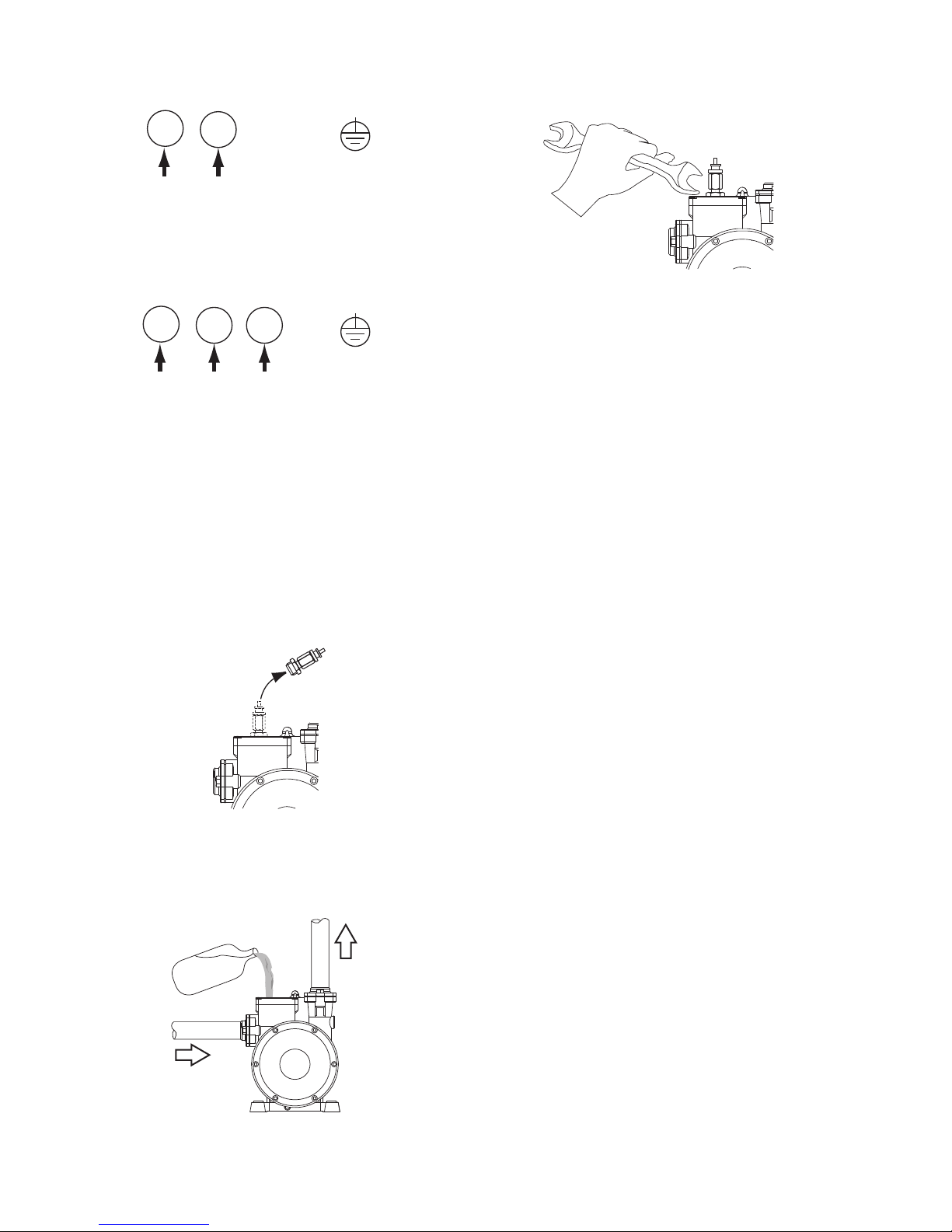
VII. Starting
1. Before starting, the pump must be primed.
Please follow the procedure as shown in Fig 2.
a. Remove the filling plug
b. Fill water in chamber
Water
c. Replace the filling plug
Fig. 2
2. Installation where the pump inlet is below
the water supply, remove the priming plug
and allow the water to flow into the priming
chamber until all air is expelled.
3. The priming procedure should be repeated
until all air is expelled and the pump delivers
a full stream of water without air bubbles.
4. The pump must always be checked for
prime if not used for a prolonged period. It is
imperative to fill the pump with liquid before
operation as dry running causes irreparable
damage to the mechanical seal.
5. When 3-phase motor is supplied, please
ensure if the rotation is correct. You can
switch any of the 2 wires to get your desired
rotation.
VIII. Precautions
1. The pump should be shut down and the
trouble corrected if the pump is running at
speed and found to have any of the following
problems:
- No liquid discharged - Not enough liquid
discharged
- Excessive vibration - Motor runs hot
2. Do not allow the pump to continually start
and stop (cycling) as this will reduce the
motor life.
3. Cycling can occur on pressure units when
the pressure tank pre-charge drops, or
where there is a leak in the discharge
plumbing.
~ 3 ~
Suction
Discharge
 Loading...