

Walrus TPRK 1T 60Hz Series, TPRK 1T 50Hz Series, TPRK 3T 50Hz Series, TPRK 5T 50Hz Series, TPRK1T 17-17 Instruction Manual
...
TPRK Series
Immersible Pump
Instruction Manual
ISO 9001 Certified
Walrus Pump Co., Ltd.


EC Declaration of Conformity
Manufacturer:
Walrus Pump Co., Ltd.
Address:
No.83-14, Dapiantou, Sanzhi Dist., New Taipei City 252, Taiwan
Declare that the machinery described:
Name : Water Pump
Model : TPRK Series
Conform to the following directive:
2006/42/EC—Machinery directive
2014/35/EU—Low voltage directive
2014/30/EU—EMC (Electromagnetic compatibility) directive
Refer to the following standards:
EN ISO 12100:2010 EN ISO 13857:2008
EN 809:1998+A1:2009 EN 60204-1:2006
EN 60335-1:2002 EN 60335-2-41:2003+A2:2012
EN 61000-6-2:2005 EN 61000-6-3:2007
R&D department manager: Kao Tien-chuan
Manager:
~ 2 ~
Please read this installation and
operating instructions carefully
before beginning installation and
operation.
1. Application
1.1 The TPRK Series is multi-stage centrifugal
pump designed for transf erring liquid
used in machine tools.
1.2 The pump can not be used to transfer
explosive liquids,such as gasoline,
diesel oil and other similar liquids.
It is only suitable for water diluted,
low viscosity, uncorrosive cooling or
lubricant liquids.
2. Model Explanation
The pump models are coded based on the
number of pump stages. Standard stages
consist of both diusers and impellers,
and null stages, for special installation
considerations, contain diuser chamber
only. The pump model is shown on the pump
nameplate.
TPRK 1T 23 - 23
E
Drain back tank structure
Number of Impellers
Number of diffuser
Standard capacity m
Model code
3
/h
3. Technical Data
1. Liquid Temperature : +0°C~+90°C
2. Ambient Temperature : Max.+40°C
3. Enclosure Class: IP54
4. Discharge Pressure: Max. 25kg/cm²
5. Submerged depth : Min. 40mm
6. Stainer Diameter: Ø2mm
7. Particle Size: 2mm
8. Liquids(maximum content of solid
particles in suspension 50g/m³)
9. Kinematical Viscosity: 32 cst (mm²/s)
10. Head: 50Hz : Up to 240M
60Hz : Up to 240M
4. Installation
The pump has hot surface on the
motor. It must be installed so that
persons cannot accidentally come
into contact the hot surface.
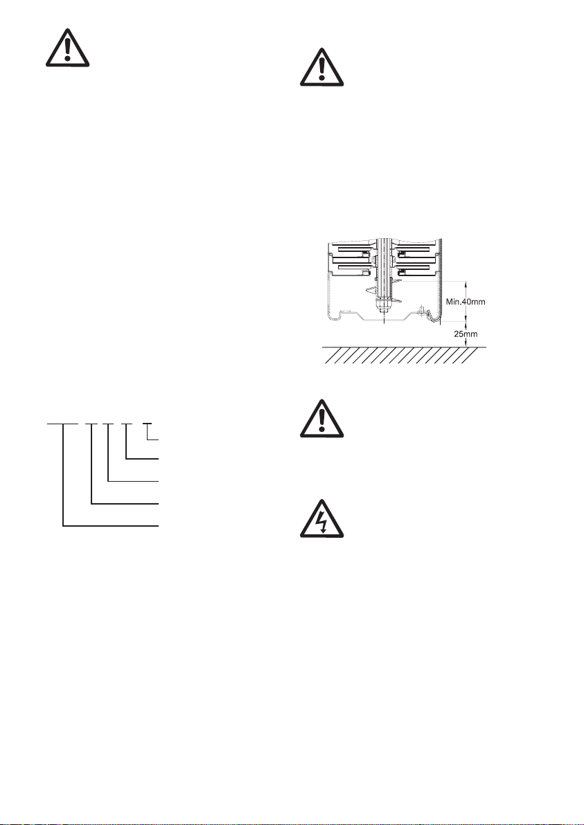
4.1. Submerged Depth
To avoid dry running and damage the pump
during operation, the minimum pump
submerged depth is 40mm as shown in Fig 1.
In addition, the bottom of the pump suction
inlet must be at least 25 mm above the
bottom of the tank.
Fig.1
5. Electrical Connection
5.1 The electrical connection should
be carried out in accordance
with local regulations. Never
make any connections unless
the electricity supply has been
switched o .
5.2. The electrical hazard warning
mark is placed outside the
connection box. Be careful.
5.3. Electrical data (voltage and frequency)
are shown on the pump nameplate.
Ver ify if these data match your
electricity supply. A Residual current
device (RCD, 30mA) should be installed
and the grounding be properly
connected for your safety.
5.4. Motors must be connected to a motor-
protective circuit breaker which can be
manually reset. Set the motor-protective
circuit breaker according to the rated
current of the motor. See nameplate.
5.5. Make electrical connection in accordance
~ 3 ~
 Loading...