

Walrus TPK Series, TPK2T5-3, TPK2T3-3, TPK2T11-3, TPK2T5-5 Instruction Manual
...
ISO 9001 Certied
WALRUS PUMP CO., LTD.
TPK Series
Immersible Pump
Instruction Manual

~ 2 ~
EC Declaration of Conformity
Manufacturer:
Walrus Pump Co., Ltd.
Address:
No.83-14, Dapiantou, Sanzhi Dist., New Taipei City 252, Taiwan
Declare that the machinery described:
Name : Water Pump
Model : TPK Series
Conform to the following directive:
2006/42/EC—Machinery directive
2014/35/EU—Low voltage directive
2014/30/EU—EMC (Electromagnetic compatibility) directive
Refer to the following standards:
EN ISO 12100:2010 EN ISO 13857:2008
EN 809:1998+A1:2009 EN 60204-1:2006
EN 60335-1:2012 EN 60335-2-41:2003
EN 61000-6-2:2005 EN 61000-6-3:2007
R&D department manager: Kao Tien-chuan
Manager:
~ 3 ~
Please read this installation and
operating instructions carefully
before beginning installation and
operation.
1. Application
1.1
The TPK series is multi-stage centrifugal
pump designed for transferring liquid
used in machine tools.
1.2 The pump can not be used to transfer
explosive liquids, such as gasoline,
diesel oil and other similar liquids.
It is only suitable for water diluted,
low viscosity, uncorrosive cooling or
lubricant liquids.
2. Model Explanation
The pump models are coded based on the
number of pump stages. Standard stages
consist of both diffusers and impellers,
and null stages, for special installation
considerations, contain diffuser chamber
only. The pump model is shown on the
pump nameplate.
3. Operating Limits
1. Liquid Temperature:+0°C~+90°C
2. Ambient Temperature: Max.+40°C
3. Enclosure Class: IP54
4. Discharge Pressure: Max.10kg/cm²
5. Submerged depth :Min. 40mm
6. Stainer Diameter: Ø2mm
7. Particle Size: 2mm
8. Liquids(maximum content of solid
particles in suspension 50g/m³)
9. Kinematical Viscosity: 32 cst (mm²/s)
10. Head: 50Hz : Up to 70M
60Hz : Up to 100M
4. Installation
The motor surface temperature
is extremely high. It must be
mounted in the save place to
avoid accidental touch.
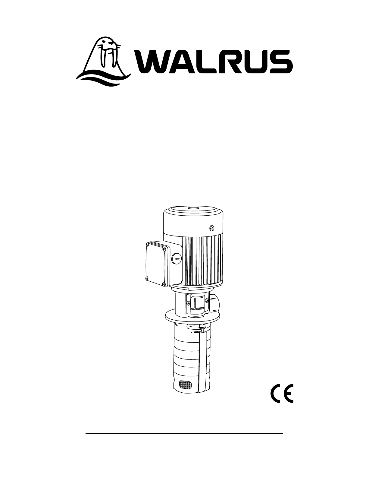
4.1. Mounting Position
The pump must be mounted vertically.
Installation is simply done by inserting the
pump into the hole on the tank top, and xed
by four bolts in mounting flange. Flange
dimensions are shown in Fig 1.
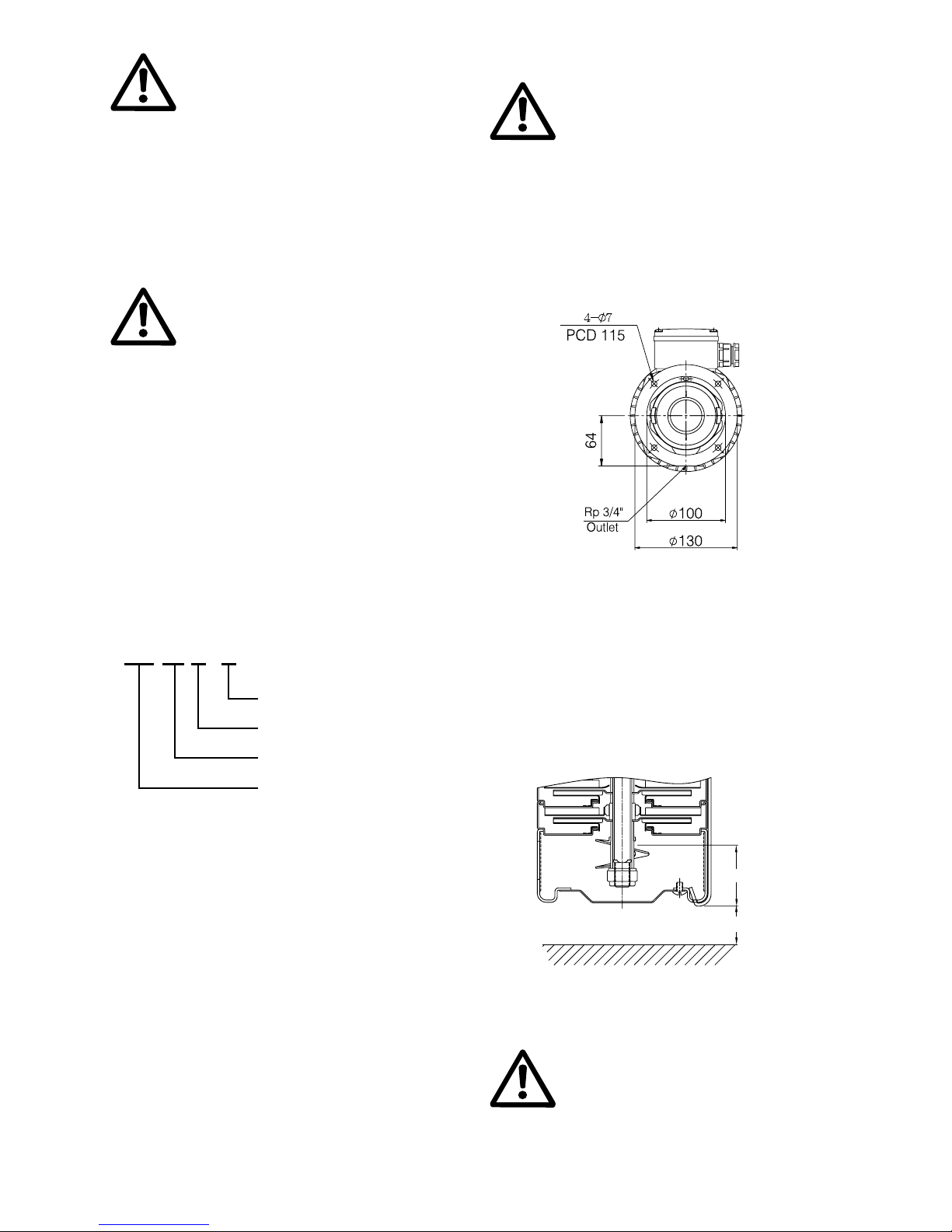
4.2 Submerged Depth
To avoid dry running and damage the
pump during operating, the minimum
pump submerged depth is 40mm, as shown
in Fig. 2. In addition, a minimum 25mm
gap between pump suction inlet and tank
bottom is required to allow for sediment
build up.
5. Electrical Connection
5.1 Electrical installation should be
carried out in accordance with
the local electrical code. Make
sure that the electricity supply
has been switched off before
electrical connection.
Fig.1
Example:
TPK 2T 3 - 3
Number of Impellers
Number of Diffuser
Standard Capacity(m³/hr)
Model Code
Fig.2
Min.40mm
25mm
 Loading...