

WallSenzr LBS-700 Series Installation Instructions Manual

OVERVIEW
The LBS-700 is a member of IR-TEC’s WALLSENZR family of
line voltage wall switch sensor designed to fit in a standard
NEMA wall box with no neutral connection required. The
sensors combine state-of-the-art passive infrared sensing
technology with décor aesthetics to provide optimal
energy-saving for all applications.
The sensor will turn ON the load automatically when it detects
the presence of an occupant, and will turn OFF automatically
if no motion is detected before the delay time elapses. To
meet compliance of specific energy code, such as CA Title
24, the LBS-700 series can be easily programmed as a
Vacancy sensor. In Vacancy mode the sensor will only turn
ON the load by pressing the push-button manually and will
turn OFF the load automatically per the sensor time delay.
The LBS-700 allows for the push-button operation to be
programmed with different manual control options.
The model LBS-700S comes with an ambient light sensor
(ALS) to inhibit the lighting if ambient light levels are higher
than required. The Accu-Set potentiometers make delay time
(TIME) and ambient light level (LUX) settings fast, easy and
accurate. Hybrid-Switching control allows the LBS-700 series
to control the lighting with high inrush current (HIC) while
switching ON, such as multiple LED or CFL lightings
connected in parallel.
INSTALLATION NOTES
SPECIFICATIONS
Line Voltage Wall Switch Sensor
INSTALLATION INSTRUCTIONS
LBS-700 Series
Power supply
Infrared sensor
Switching control
Inrush current
Detectable speed
Mounting height
Ambient light level
Delay time setting
Op. humidity
Op. temperature
Dimensions
Detection coverage
Maximum load
120/277VAC, 60Hz
Incandescent/Halogen – 800W (VA)
Fluorescent Ballast/CFL – 800W (VA)
Ballast Electronic (LED) – 500/800VA@120/277V
Motor – 1/6 HP
Dual element pyroelectric
Zero-cross Hybrid-Switching
Max. 80A, 20 mS
1~10 ft./sec. (0.3~3 m/sec)
3 ~ 5 ft. (90~150 cm) above the floor
Major motion - 30 ft x 40 ft (W x L) @4 ft high
Minor motion - 20 ft x 20 ft (W x L) @4 ft high
7 levels, from dark to 24 Hr., LBS-700S only
T/1’/3’/5’/10’/20’/30’ , T=10 sec. for testing
Max. 95% RH, non-condensate
-40°F ~ 131°F (-40°C ~ 55°C)
4.13”H x 1.77”W x 1.65”D (w/mounting plate)
INDOOR USE ONLY
Utilisation a L'interieur Uniquement
AVERTISSEMENT & PRUDENCE
WARNING & CAUTION
Risque de choc électrique - Débranchez l'alimentation avant
l'entretien.
NE PAS contrôler une charge supérieure à la capacité spécifiée pour
éviter d'endommager le capteur ou la propriété.
Installer et utiliser ce capteur conformément aux codes et règlements
électriques.
Ce dispositif est destiné à être installé par un électricien qualifié. NE
PAS tenter de réparer.
DETECTION COVERAGE
Top view
Side view
Minor motion
40’
4’
7’
30’
40’
20’
20’
Major motion
The sensor is more sensitive to the movements
“crossing” the detection zones than “toward” or “away”
the sensor. To obtain better sensitivity, ensure the sensor
to have clear field of view for the occupant’s motion within
the desired coverage.
The closer movement is to the sensor, the more sensitive
the sensor is.
The sensor should be mounted within the specified
mounting height for optimal performance.
Avoid blocking the sensor with any obstacles, such as
door, plant, partition or furniture. As a general rule, every
occupant within the desired range should be able to
clearly see the sensor.
Do NOT mount the sensor directly above or nearby a heat
source, or where unintended motion (e.g. hallway traffic)
will be “seen” by the sensor.
1.
2.
3.
4.
5.
P/N: 058-70000-004 Printed in Taiwanwww.irtec.com
This product may be covered by one or more U.S. patents or patent applications.
Please visit www.irtec.com for more information.
Risk of Electric Shock Disconnect power supply before servicing.
DO NOT control a load in excess of specified ratings to avoid
damaging the sensor or the property.
Install and use this sensor in accordance with electrical codes and
regulations.
This device is intended to be installed by a qualified electrician.
DO NOT attempt to service or repair.
IR-TEC International Ltd. warranties this product to be free of defects
in materials or workmanship for a period of five years from date of
shipment. There are no obligations or liabilities on the part of IR-TEC
International Ltd. for consequential damages arising out or in
connection with the use or performance of this product or other
indirect damages with respect to loss of property, revenue, or profit,
or cost of removal, installation or reinstallation.
WARRANTY
INSTALLATION
Ensure the power has been turned OFF at the circuit
breaker.
Prepare the wires with proper length (cut the excessive
length, if necessary) and strip for connection. Connect
the sensor wires to the wires of line voltage and load
according to the above wiring diagram of desired control.
Carefully bend the wires in the wall box after all wires are
properly connected. Mount the sensor in the wall box
with the screws provided.
Conduct sensor operation test (refer to the TESTING
section). Replace the wall plate cover after sensor testing
and setting completed.
1.
2.
3.
4.
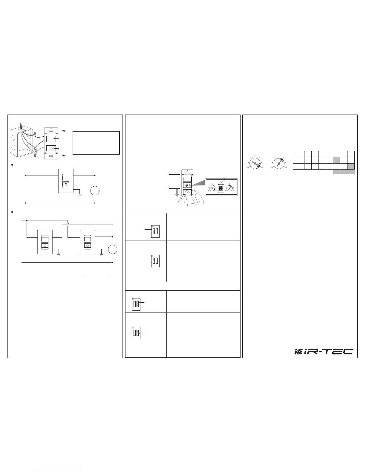
WIRING DIAGRAM
3-Way Control
Sensor Mode
Push-button Control
Occupancy Sensor
(Auto-ON, Auto-OFF)
Occupancy sensor switches the light ON
automatically when it detects the presence
of an occupant. The sensor will switch the
light OFF automatically if no occupant
activity has been detected before the time
delay elapses.
ON
1 2
Vacancy Sensor
(Manual-ON, Auto-OFF)
Vacancy sensor requires the user to
manually press the push-button to turn ON
the light. The sensor will switch the light
OFF automatically if no occupant activity
has been detected before the time delay
elapses.
NOTE - The sensor will automatically turn
ON the light if it detects occupant activity
within 30 seconds after time delay elapsed.
Presentation Mode
Pressing the push-button during occupied
state will turn OFF the load immediately
and hold off until the push-button is
pressed again.
In Presentation Mode (PM), pressing the
push-button will turn OFF the lights
immediately, and the lights will remain off
even if motion is detected. Pressing the
push-button again will turn the light ON
and the sensor will operate per its settings.
If the time delay expires and no occupant
activity has been detected, the sensor will
return to its normal operation. The lights
will turn on with the next motion detected.
SW1=ON
Manual ON/OFF
ON
1 2
SW1=OFF
ON
1 2
SW2=ON
ON
1 2
SW2=OFF
Sensor
Red
Black
Black
Hot(Black)
Line
120/277VAC, 60Hz
Green
Ground
Load
White
Neutral(White)
SensorSensor
RedRed
Black
BlackBlack
Hot
(Black)
Line
120/277VAC, 60Hz
Load
WhiteNeutral
(White)
Green
Ground
Green
Ground
OPERATION
The LBS-700 series wall switch sensor employs passive
infrared (PIR) sensing technology to monitor the occupancy
status within its coverage, and control the connected load as
per sensor setting. The sensor can be programmed to control
the load as an Occupancy Sensor or Vacancy Sensor via
setting DIP switch #1. The push-button operation can be
programmed to turn the load ON and OFF manually or in
Presentation Mode (PM) for specific requirement via setting
DIP switch #2.
The sensor may be available with other control options,
consult a qualified electrician or contact info@irtec.com
for assistance.
This is the delay time that the LBS-700 series sensor will hold
the load on after the last motion detected. The factory setting
is 10 minutes, and it can be changed by pointing the
arrowhead of potentiometer to the specific position.
TIME - Delay time
This is the threshold of ambient light level that the LBS-700S
sensor will inhibit switching on the load. The factory setting is
ALS disabled (24 Hr) for ease of testing, and it can be
changed by pointing the arrowhead of potentiometer to the
specific position.
LUX – Ambient light level (LBS-700S only)
TESTING
Restore line voltage power for the sensor at circuit breaker
(power up time is approx. 1-5 min).
An LED behind the sensor lens will blink to indicate the
motion sensed.
Replace the wall plate cover after completing sensor testing
and setting.
1.
2.
3.
NOTE: The connected load will be switched on as delay time
set (factory default 10 minutes) once apply the power. The
delay time can be set to the shortest (10 seconds) for ease of
testing. Ensure to set the TIME as desired for optimum
operation after testing.
LUX
1 7
2 6
3 5
4
TIME
1 7
2 6
3 5
4
LUX
TIME T
POS. 1 2 3 4 5 6 7
1’ 3’ 5’ 10’ 20’ 30’
5 10 30 50
100 150 24H
Factory Set
LENS
PUSHBUTTON
Single-Pole Control
The GREEN wire MUST
be connected to the
GROUND for operation
NOTE:
To change the sensor
operation mode or
settings, press the
push-button cover
and slide it down as
shown.
The LBS-700S features ambient light sensor to inhibit
unnecessary lighting when ambient light is higher than the
level set. The time delay (TIME) and ambient light level (LUX)
settings can be changed by rotating the respective Accu-Set
potentiometer at different positions.
SETTING
Slide
ON
12
LUX
TIME
Press
&
ON
1 2
LUX TIME
DIP
Switch
 Loading...