

Page 1
1
EN
External corner solutions
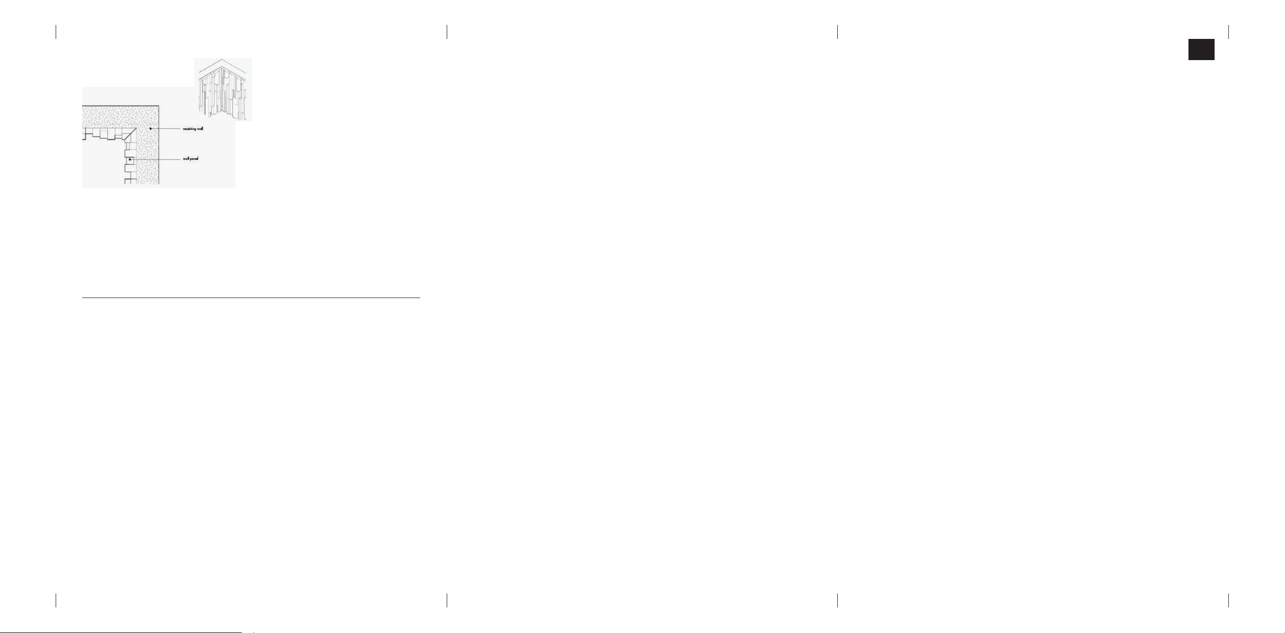
wood vertical
If a vertically placed corner solution is prefer
red we recommend one row of the wall panel
overlap so the side of one for the panels is
visible.
Internal corner solutions wood vertical
In case of an internal corner a seamless
unbroken row of vertical panels is achieved by
LTL Home Products, Inc
(800) 360-1585
ltlhomeproducts.com
joining corresponding panels using a mitered
edge. Connect the return wall using the other
half piece from the joining panel.
Disclaimer
Our panels are made entirely of authentic,
reclaimed hardwoods from a variety of
sources. Wood is a natural material that
contains distinctive characteristics in grain
colour and texture. Photographs and physical
samples should be viewed as illustrative of the
collection they represent;in no way should
they be regarded as being definitive or of
guaranteeing an exact match. Each individual
panel is unique. Please note that no returns
are offered for product that has been installed.
With this in mind we always advise that you
take the opportunity to experiment with
different panel arrangements prior to final
installation.
Your statutory rights are not affected.
Introduction
Congratulations! You have acquired your very
own piece from the Wallscapes collection. This
means that you are about to enhance your
walls with hardwoods that are full of character.
Your eye for design will inspire for years to
come.
Our wall panels have been thoughtfully crafted
and designed for all types of interiors. The
manual will guide you through the installation
process in five simple steps.
Two golden rules
The two golden rules for the best result are:
1 Paint your receiving wall black prior to
installation.
2 Place the wall panels in a random bond.
You will find these golden rules clearly
marked in bold writing later in this
installation manual.
Owner / installer responsibility
All of our panels are thoroughly inspected to
ensure that you receive only the very finest
specimen hardwoods nature has to bestow. As
all of our materials are natural however some
natural variations in grading may occur. It is the
installer’s responsibility to check the suitability
of all panels prior to installation. In the highly
unlikely event that any defects are found to be
present, you should contact your supplier
immediately. Do not install panels you suspect
to be defective as we cannot ac-cept returns
once panels have been installed.
It is the installer’s responsibility to ensure that
the project site is suitable and that the panels
are correctly installed (see later). The
manufacturer accepts no responsibility for
failure due to incorrect or inappropriate
installation.
be fully enclosed to the elements and all
receiving walls should be completely dry.
The receiving wall
Our wall paneling may be applied to a range of
receiving surfaces. For the best results we
recommend fixing to an even surface. Flat walls
are ideal but by no means vital; a small degree
of unevenness is acceptable and will not cause
problems.
Condition of receiving wall - general
In general, surfaces should be clean and free
from any loose material or debris. They should
be completely dry and structurally capable of
supporting the aggregate panel weight,
together with that of any backing strata
(where used).
For the best result it is recommended to paint
the receiving wall black before mounting.
Tool Check list and accessories needed
Tools you will need for the job.
All installations
Broom and/or vacuum, spirit level and/or
cross laser level, handsaw, table saw and/or
crosscut saw, tape measure, pencil, utility
knife, extension cord, ladder and personal
protective equipment.
For mounting with adhesive
Silicon gun and elastic MS polymer High Tech.
For mounting with tacker
Tacker, brads 1/20" thickness and 1.2" - 2"
depending on the wall panelling type being
installed
Project site – Inspection
The Wallscapes collection is suitable solely for
3D Wall or installation. The project site should
Page 2
3
EN
4
EN
Wall panel
Receiving wall
Receiving wall
Wall panel
Wall panel
Wooden
Receiving wall
Wall panel
Anodized
aluminium
profile
Anodized
aluminium
profile
Receiving wall
Receiving wall
2
EN
Step 1 Step 3
-
- - - -
-
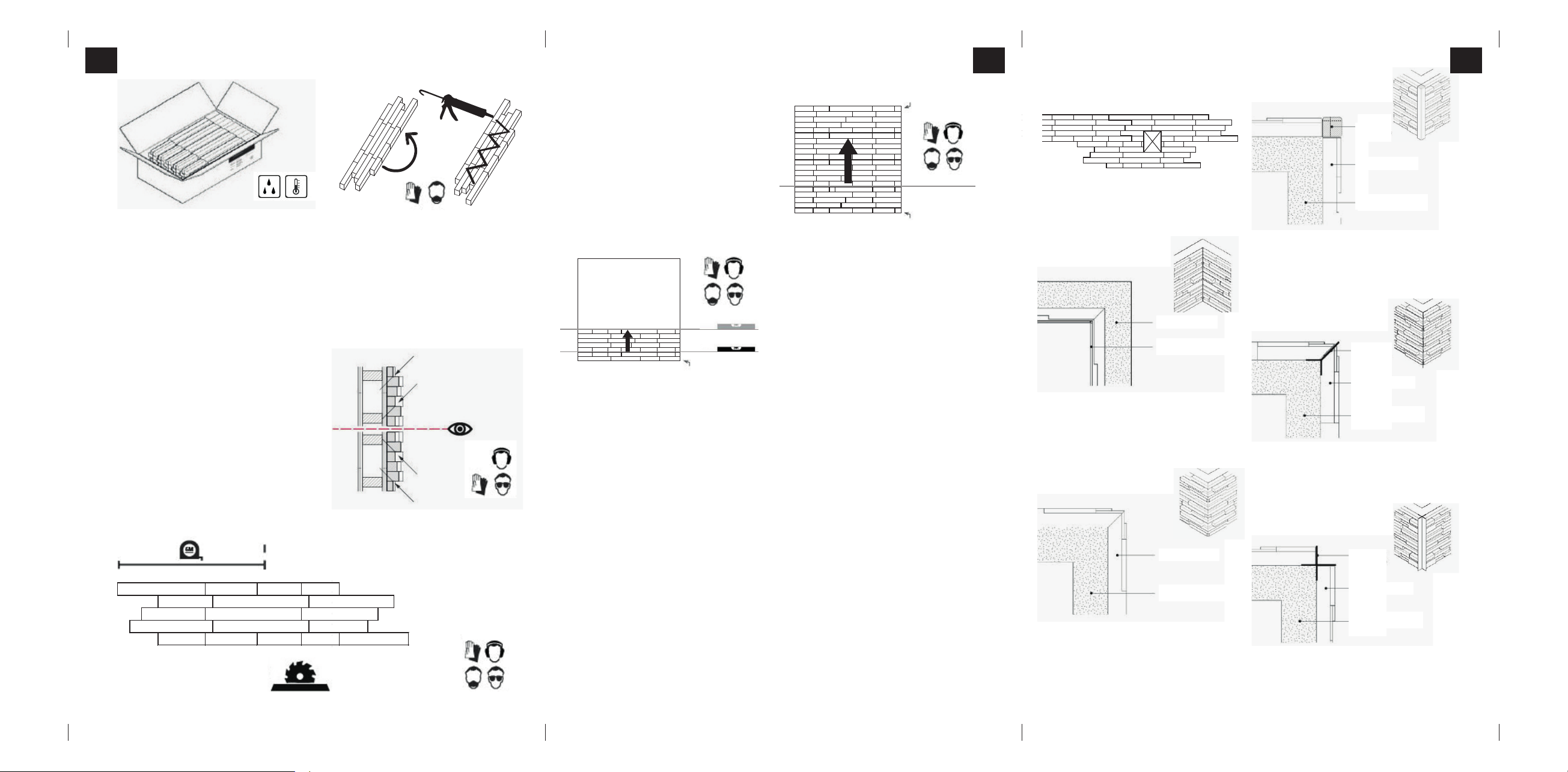
Step 1: Handling and acclimating your wall
Unload and handle panels with care. For best
results, we recommend that you store panels in
their new environment for a period of one week
prior to installing them. Wood is a natural
material which reacts to it’s environment,
therefore a degree of shrinkage or expansion
may be expected depending on the nature of
the panels’ new home. Allowing the panels to
acclimate in this way prior to installation means
that the wood will have significantly stabilized
before it is affixed to the wall. A better finish
may therefore be achieved. Panels should not
be delivered to site unless and until the building
is completely closed to the elements.
Step 2 : The first tile
For the most efficient coverage, cut the first tile
directly in half, widthwise (with a table saw or a
cross-cut saw). Then take one of the half tiles,
align the newly created straight edge with the
left edge of the wall and fix in place. The other
half tile may be used to start subsequent rows
as described in step 5.
1 week
Mounting using adhesive
Panels may be mounted to a range of surfaces
using the correct fixing medium and in most
cases we recommend using a strong elastic MS
polymer adhesive High Tech. As a guide, you
will require roughly 290 ml adhesive for every
22 sq ft of paneling.
Mounting using tacker
Where panels are to be installed onto a
wooden backing surface, a tacker device may
be used as an alternative (or in addition) to a
polymer adhesive. For best results when
using a tacker, take care to ensure that the
appearance of the brads is minimized. When
affixing wall panels above eye-level, brads
should be ‘shot’ at a downwards angle. For
panels below eye-level, shoot the brads at an
upwards angle. Brads at eye-level should be
shot into corners of the panel and between
the lats.
3/8"
Step 4
Placing the first rows of your wall
Position the first panels in a straight row along
the wall. We recommend using a spirit level or
cross laser to mark a straight line on the wall as
a guide before positioning the panels. Place the
first half panel on the left side of the wall in the
manner described in Step 2 and follow the
spirit line. With this golden rule #2 a random
bond is created which makes the joints
disappear.
Continue with the other panels until you reach
the end of the row, using a table saw
or a cross-cut saw to cut the final panel to size.
The leftover piece of panel may be used to
start the second row. For best results, we
recommend an irregular panel formation; that
is to say that you do not exactly repeat the
formation of the panels in successive rows.
After installation of the first 5 rows check that
straight lines have been maintained, correc ting
if necessary.
Step 5
3/8"
3/8"
Mounting your wall
Place the panels in an irregular (mixed)
formation and work first upwardly in rows
until you come to the top of the wall. In each
row, the leftover portion of panel from the
end of one row may be used as the starting
panel for the following row. Remember that
this is subject to it’s suitability to maintain the
overall irregu-lar formation; where it is not
suitable, cutting to an alternative size should
make it so. We advise leaving a 3/8" expansion
space both below and atop of the wall.
LARGE SURFACE AREAS
Expansion joints in building structure
For both mounting using adhesives or using a
tacker in projects with large surface areas it is
always advised to accommodate the
expansion joints in the building structure by
allowing the same expansion space in the wall
paneling. This space may be filled with a
flexible sealant.
Layout and expansion space
When the wall paneling area exceeds 33 ft in
width and/or 100 ft in length, additional
expansion space must be incorporated into
the field, as well as at the perimeter and all
obstructions.
Special solutions power
sockets and light switches
Light switches and power sockets can be
integrated by cutting a hole within the panel.
Always measure carefully before cutting the
hole.
Internal corner
solutions wood
In case of an internal corner a seamless
unbroken row of panels is achieved by joining
corresponding panels using a mitered edge.
Connect the return wall using the leftover
piece from the joining panel.
External corner
solutions wood
A seamless corner/unbroken row of panels is
achieved by joining corresponding panels
using a mitered edge. Connect the return
wall using the leftover piece from the joining
panel.
External corner
solutions wood
molding
Using a square wooden molding will delineate
joining walls and put a strong emphasis on the
corner itself. We recommend that you use a
well matched wood type for this solution.
External corner
solutions metal
If a narrower, corner-defining solution is
preferred we recommend using an anodised
or powder coated aluminium profile of 3/16"
thickness, positioned within the miter joint.
External corner
solutions metal
Wall panel
For this open corner solution we recommend
using an anodised or powder coated aluminium profile of 2" x 2".
 Loading...