

Page 1
progress & innovation 1/46
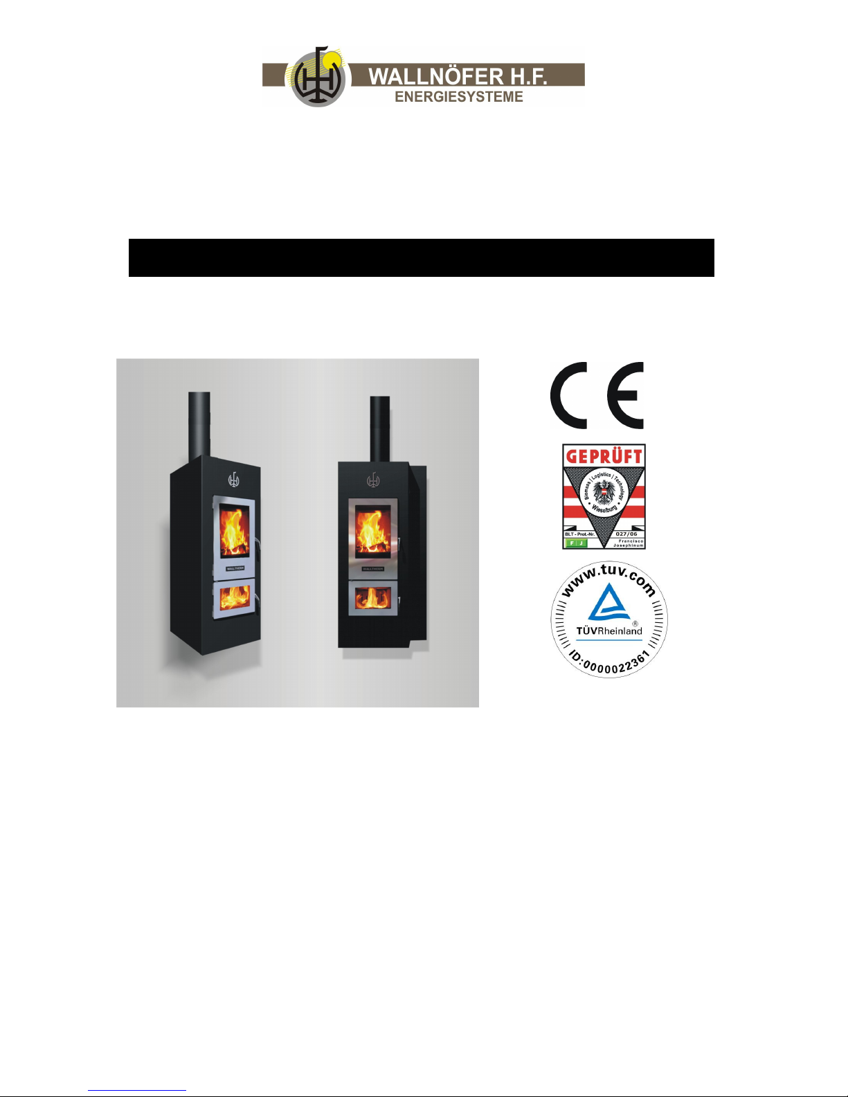
OPERATING MANUAL:
Instructions for use & maintenance of the
Walltherm® Version / 12.1
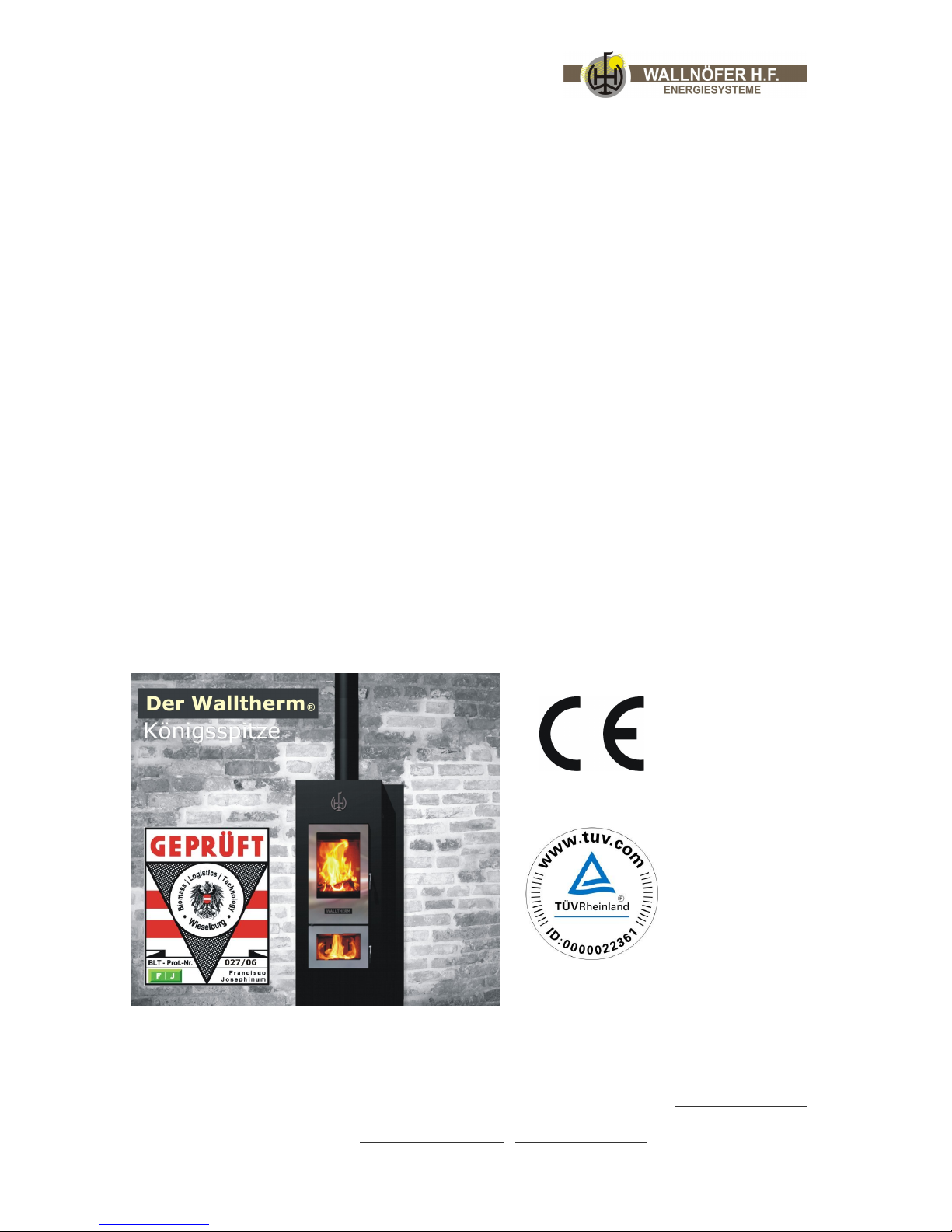
The first natural down-draught wood gasification stove
for the living room.
Dear stove-owner,
You have made an excellent choice purchasing the Walltherm® stove/boiler for
your living room. Especially in connection with a heat storage tank, it offers you
all the advantages of a radiant heat stove for the living room and furthermore,
an economical heating system for your whole house. Please study this manual, it
explains how the stove works, how you should operate it and how it has to be
maintained.
For further information, please contact the manufacturer or any authorized
Walltherm dealer
Page 2

progress & innovation Vers. 12.1 2/46
! In any case the laws and norms valid in the installation country
have to be respected.
This stove has been developed for the following uses:
due to the contemporary design and the visible fire it can be perfectly put up in the living
room
heating of the living room through radiant heat
heating of distant rooms with water based radiators, underfloor- or wall heating from the
boilerDHW through the hot-water tank/store
integrated hotplate for cooking and therefore ideal for holiday homes
THEREFORE: the requirements for the complete heating of an average country house
are covered (heating of rooms and domestic hot water)!
FEATURES OF THE STOVE:
two times visible fire through temperature resistant glass
rapid heating due to big radiant surfaces
boiler function with integrated heat exchanger
wood-burning system, consequently economical and clean burning
small hotplate for cooking
GENERAL INFORMATION:
PURPOSE:
The Walltherm® stove has been developed for the optimal burning of air-dried natural
wood, wood chips and (partly) briquetts. Do not burn any wood/paper/cardboard that
has been painted or colored, not should you use barbecue igniters or coals because
anything that isn´t natural wood can produce acids while burning. Those acids can
damage the stove and the heat exchanger!
The stove must not be used for burning any other
materials including coal or waste.
The heater (wood gasification stove) Mod. Walltherm®, invented by the company
Wallnöfer H.F. GmbH, complies with the Machine- and Safety Regulations of the
European Union guideline 98/37/EWG and consequent amendments. The stove has been
tested and registered by BLT-Wieselburg (AUT), VKF (Switzerland) and TÜV
Rheinland (GER).
This operation manual is directed at the owner of the stove Mod. Walltherm, the
tradesman who installs it, the operators, and the service personell.
In any case of doubt or for further information concerning the manual, please contact the
producer or any authorized Walltherm dealer. Please quote the number of the paragraph
and name the topic in question.
Page 3
progress & innovation Vers. 12.1 3/46
This operating manual is protected by copyright and it (or any part thereof) must not be
printed, copied or reproduced without prior consent of Wallnöfer H.F. GmbH.
Technical information, graphics, and specifications included in this manual must not be
published/distributed.
The principle of the double combustion and its advantages
Generally: In a wood burning stove, a correctly burning flame emits the same amount
of carbon dioxide (CO2) as would be emitted through the natural decomposition of the
wood itself.
The quantity of CO2 produced by combustion or decomposition of a tree is equal to the
quantity of CO2 that the tree would have extracted from the environment, releasing
oxygen into the air whilst utilising the carbon for growth during its lifetime.
Unlike wood, when fossil fuels are burned – which are not renewable, like coal, diesel oil,
gas – a huge amount of CO2 accumulated in the course of millions of years is emitted
into the atmosphere, increasing the green-house effect. Consequently, the use of wood
as fuel maintains the perfect equilibrium of nature because it is a renewable fuel of which
burning is compatible with nature’s life cycle.
The principle of clean combustion is in perfect harmony with these characteristics and
Wallnöfer H.F. GmbH always adheres to it when designing their products.
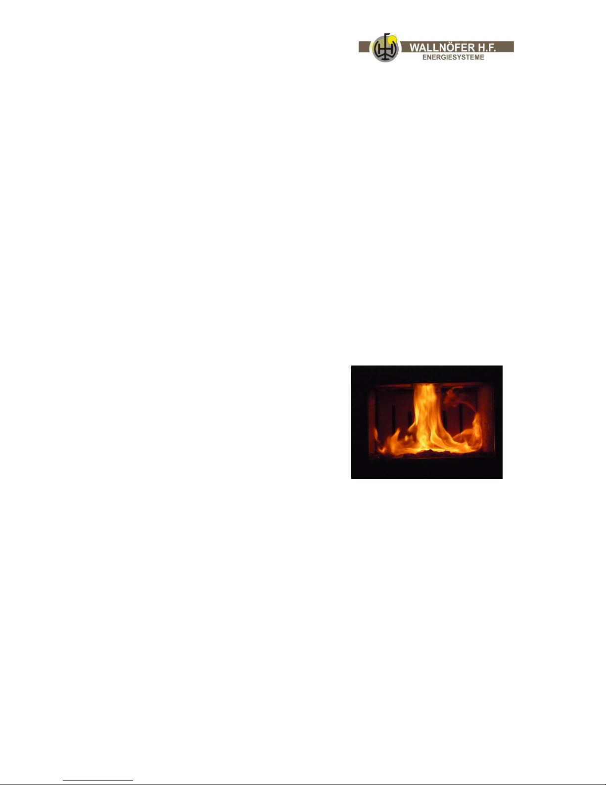
Double combustion: What exactly do we mean by
clean double combustion and how does it work? By
controlling the flow of primary air and by adding
secondary air, secondary combustion, or postcombustion, takes places. This is indicated by a
second characteristically clearer and stronger flame
below (?) the main flame. By adding new oxygen,
this flame consumes the unburned gasses,
remarkably improving heat production and reducing
the harmful emission of CO (carbon monoxide)
caused by incomplete combustion. This is a unique
feature of the Walltherm stove for the living room.
Page 4

progress & innovation Vers. 12.1 4/46
Index
1) Introduction
1.a. Symbols
1.b. Intended use
1.c. Purpose and contents of the
manual
1.d. Keeping the manual
1.e. Updates of the manual
1.f. General information
1.g. Main accident prevention
regulations to comply with
1.h. Guarantee
1.i. Manufacturer’s liability
1.j. User characteristics
1.k. Technical assistance
1.l. Spare parts
1.m. Identification plate
1.n. Delivery of the stove
2 Safety Instructions
2.a. Instructions for installers
2.b. Instructions for users
2.c. Instructions for maintenance
engineers
3 Parts list for the stove
3.a. Parts
4 Handling and Transport
5 Preparing the place of
installation
5.a. Safety precautions
5.b. Combustion
5.c. Preparing the place of
installation
5.c.1. Limitation of space around the
stove
5.c.2. Limitation of space above the
stove
5.c.3. Combustion air
5.c.4. Smoke outlet pipe
6 Installation
6.a. Leveling the stove
6.b.1 Connecting Electricity
6.b.2 Earthing
6.c. Important information
6.c.1. Doors
6.c.2. Thermal safety drain
6.c.3. Circulation pump
6.c.4. Density
6.c.5. Permissible max/min
temperatures
6.c.6. Cleaning
7 Using the stove - Lighting
7.a. Control
7.b. Lighting phase
7.c. Loading the fuel
7.d. Permissible and suited fuels
8 Maintenance and cleaning
8.a. Safety precautions
8.b. Routine maintenance for the
user
8.b.1. Cleaning the stove
8.b.2. Cleaning the glass
8.b.3. Cleaning the smoke outlet
8.b.4. Controlling seals
9 Recognizing errors and taking
measures against faults
10 Saving energy
11 Concept of water pipes
12 Safety functions
13 Technical features/data
Page 5
progress & innovation Vers. 12.1 5/46
!
1. Introduction
Do not install or use the stove before you have read and understood the contents of this
manual. In case of doubt at any time do not hesitate to contact Wallnöfer H.F. GmbH for
information.
Wallnöfer H.F. GmbH reserves the right to modify the technical and/or functional
specifications and features at any time without prior notice.
1.a. Symbols
Important points in this manual are highlighted with the following symbols:
Indication: indications concerning the correct use of the stove and the
responsibilities of those using it.
Attention: a particularly important note is written here.
Danger: Here you are warned of the possibility of bodily harm or material
damages.
1.b. Use of the stove
Walltherm is an innovative, technologically advanced stove for heating, burning fuels like
firewood and wood briquettes providing a healthy and safe way of heating.
This stove features the dual primary and secondary combustion system with positive
effects both on efficiency and on emission of “cleaner smoke”.
The application of the stove and its configurations as described above are the only ones
permisable by the manufacturer. Do not use the stove in disagreement with the
instructions provided.
The described use of the stove is applicable only for stoves in full structural,
mechanical and engineering condition.
The Walltherm, produced by Wallnöfer H.F. GmbH, must only be used indoors.
1.c. Purpose and contents of the manual
Purpose
The purpose of the manual is to provide the operator with the fundamental knowledge to
allow the user to take the necessary precautions and to have all the human and material
resources required for its correct, safe and lasting use.
Page 6

progress & innovation Vers. 12.1 6/46
Contents
This manual contains all the information necessary for installation, use and maintenance
of the Walltherm stove. By complying scrupulously with the contents of this manual you
will ensure a high degree of safety and productivity of the stove.
1.d. Keeping the manual
Keeping and consulting the manual
The manual must be kept in a safe, dry place and be available at all times for
consultation by the user and by those who see to its installation and maintenance.
The manual with its instructions for operation and maintenance is an integral part of the
stove.
Deterioration or loss
If required, ask Wallnöfer H.F. GmbH for another copy of the manual.
Selling the stove
If the stove is sold, the user must give the manual to the new owner.
1.e. Updating the manual
This manual reflects the state-of-the-art at the time the appliance was put on the
market.
1.f. General information
Information
If there is an exchange of information with the stove manufacturer, please quote the
serial number and identification data which you will find on the stove’s identification
plate.
Liabilities
Upon delivery of this manual Wallnöfer H.F. GmbH declines all liabilities, both civil and
penal, for any accidents that may derive form the total or partial failure to comply with
the specifications contained in it.
Wallnöfer H.F. GmbH also declines all liabilities resulting from an improper use
of the stove, incorrect use by the user or resulting from unauthorised
alterations and/or repairs, or the use of spare parts that are either not
genuine or not specific for this particular model.
Extraordinary maintenance
Extraordinary maintenance must be carried out by personnel qualified to work on the
stove model to which this manual refers.
Responsibility for installation
It is not the manufacturer’s responsibility to carry out the works
needed to install the stove. Such works are entirely up to the installer who is
requested to check the flue and air intake and to check if the installation
solutions proposed are feasible. In addition, all the safety standards
established by the relevant law in force in the place of installation must be
complied with.
Page 7

progress & innovation Vers. 12.1 7/46
Use
Use of the stove is subject to compliance with all the safety standards established by the
relevant laws in force in the place of installation besides the prescriptions contained in
this manual.
1.g. Main accident prevention regulations to comply with
a) EEC directive 73/23: “electrical material for use within certain voltage limits”.
b) EEC directive 89/336: “grouping of the laws of the member states relative to EMC”.
c) EEC directive 89/391: “putting into practice the measures to promote improvement
of the safety and health of workers during their working hours”.
d) EEC directive 89/106: “concerning the grouping of legislative, regulating and
administrative guidelines of the state members on the subject of construction
products”.
e) EEC directive 85/374: “concerning the grouping of legislative, regulating and
administrative guidelines of the state members on the subject of liability for
damages due to faulty products”.
1.h. Legal guarantee
Wallnöfer H.F. offers 5 years of guarantee for the body of the Walltherm, exclusiv spare
parts like combustion jets, grid, glass, seals, cat, fireclay.. For all the valves an other
components the user may only make use of the legal guarantee, as under the EEC
directive 1999/44/CE, if he has scrupulously complied with the regulations indicated in
this manual, and more specifically:
to work always within the stove’s range of use
maintenance must be constant and accurate
only allow people who are capable and who have been suitably trained to use the
stove.
Failure to comply with the regulations contained in this manual will invalidate the
guarantee immediately.
In any case of possible legal guarantee the installation of the stove must have been
carried out by people who are capable and who have been suitable trained to use the
stove. Furthermore, a copy of the installation record has to be delivered to Wallnöfer H.F.
GmbH.
Wallnöfer informs that the following cases aren`t query reason:
Fireclay:
Because of the high temperature loading, the fireclay can get cracks, in this case it isn`t
necessary to exchange the components, the isolation function is still ensure. The
exchange is only necessary if the fireclay falls apart.
Noise:
Until the warming and cooling phase of the body made of steal it is normal that you hear
some noise.
Page 8

progress & innovation Vers. 12.1 8/46
Coating:
Please control the external coating before you install the Walltherm, when you find defect
parts please contact immediately your reseller.
After the installation of the Walltherm we can only resolve the problem with sprays.
To avoid coating problems during the operation please take note of the following tips:
a) Please clean the external parts only with water and soap, do never use alcohol or
similar agressiv cleaning liquids.
b) To protect the upper side of the Walltherm® please close the exhaust fume flap
(5) when the gas temperature reaches about 300 - 350°C. (look chapter: 7 Using
the stove – Lighting)
Cooking plate and doors:
Because of the high temperature loading, the colour of the doors and the cooking plate
will change. When you grid of this parts you can get the origal colour.
1.i. The manufacturer’s liabilities
The manufacturer declines all civil and penal liabilities, direct or indirect, due to:
an installation that fails to comply with the laws in force in the country and with the
safety rules and regulations;
failure to comply with the instructions given in the manual;
an installation by unqualified and untrained personnel;
use that fails to conform to the safety directives;
alterations and repairs on the appliance not authorised by the manufacturer;
use of spare parts that are either not genuine or specific for this particular model;
lack of maintenance;
exceptional events.
1.j. User characteristics
The person who uses the stove must be an adult and responsible, with al the necessary
technical know-how to carry out routine maintenance of the mechanical and electrical
components of the stove.
Do not let children near the appliance to play with it when it is working.
1.k. Technical assistance
Wallnöfer H.F. GmbH is able to solve any technical problem concerning the use and
maintenance of the appliance’s whole life cycle. The main office will help you find the
nearest authorised assistance centre.
Page 9
progress & innovation Vers. 12.1 9/46
Abb.1 .m
1.l. Spare parts
Use genuine spare parts only!
Do not wait until the components are worn from use before changing them.
Changing a worn component before it breaks makes it easier to prevent accidents that
could otherwise lead to serious harm to people or damage to things.
Carry out routine maintenance checks as described in the “machine
maintenance and repair” chapter!
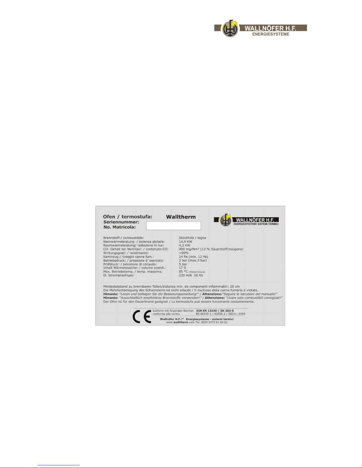
1.m. Identification plate
The plate shown in fig. 1 m can be found on the stove’s left and gives all the machine’s
features including the manufacturer’s data, serial number and CE marking relative to the
electrical system.
1.n. Delivering the stove
The stove is delivered accurately packed in cardboard and fixed to a wooden pallet so it
can be handled by elevator trucks and/or other means.
You will find the following items inside the stove:
use, installation and maintenance manual;
cleaning brushes for the vertical and horizontal flue and air intake
a brush for the ashes
a fire hook
a cold handle for pulling the hearth out;
Page 10
progress & innovation Vers. 12.1 10/46
2. Safety Precautions
2.a. Instructions for the installer
comply with the indications given in this manual
check that the flue and air intake are suitable for the type of installation opted for
(12 pa draft)
the electrical connections must not be done using temporary or non-insulated leads
make sure the electrical system’s earthing is effective
always use individual safety devices and other protections means.
2.b. Instructions for the user
the stove must not be used without having it filled with water
Since the stove is an appliance that heats, its outer surfaces can get very hot. For
this reason we advise maximum caution when it is working, in particular:
not to touch or go near the glass door as you could get burnt;
not to touch the flue and air intake;
not to do any type of cleaning;
not to pull out the ashes;
not to touch the lower glass door;
make sure that children are kept away.
comply with the indications given in this manual
comply with the instructions and warnings given on the plates on the stove
these plates are accident prevention devices and as such must be easily and
perfectly illegible it; it is compulsory to change them, asking the manufacturer for
an original plate
only use fuel that complies with the indications given in the chapter referring to fuel
characteristics
keep strictly to the routine and extraordinary maintenance programme
do not use the stove if there is a malfunction, a suspicion of breakage or unusual
noises
do not throw water on the stove when it is lit or to put the fire out in the hearth
do not clean the stove until the structure and ashes are completely cold
all works must be carried out in maximum safety and calmly.
2.c. Instructions for the maintenance engineer
comply with the indications given in this manual
always use individual safety devices and other protection means
before embarking on any maintenance work the stove must be completely cold
even if only one of the safety devices is incorrectly calibrated or not working, the
stove is to be considered “not working”
the electricity must be disconnected before any work is done on switches and
connectors.
Page 11

progress & innovation Vers. 12.1 11/46
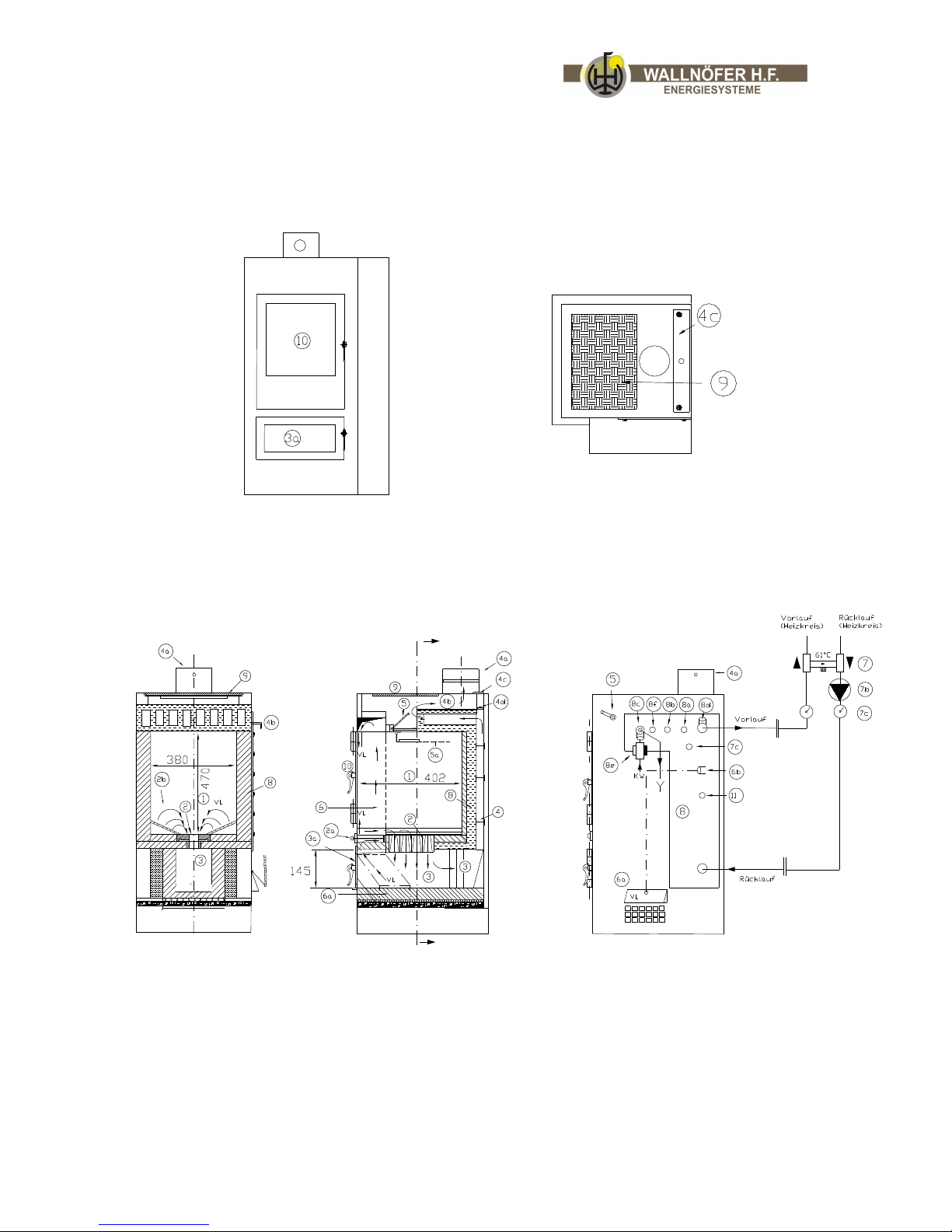
3. Parts list of the stove
3.a. Spare parts/components
1 Upper combustion chamber
2 injektor block with secondary air feed
2a Secondary air knob
2b Grid
3 Lower combustion chamber (gas combustion tunnel)
3a Door with glass to lower combustion chamber
4 Smoke channels
4a Stove pipe flange with thermometer
4b Horizontal smoke channels
4c Opening with lid for access to smoke channels for cleaning
4d Adjustable lid for smoke diversion
5 Exhaust fume flap (function: lever in horizontal position = flap closed, lever
pointing down = flap open)
5a Smoke baffle with opening and cover for hotplate (cooking)
6 Combustion air intake channel to upper and lower cross channel
6a Air inlet with thermostatically controlled flap
6b Safety thermostat for control of combustion air intake
7 Thermostatically controlled 3-way valve set to open at 60°C – 70 °C
7b Circulation pump
7c Thermometer
8 heat exchanger
8a Thermostat/sensor for pump on/off control
8b Safety valve to 3 bar for draining how water in case of overheating
8c heat exchanger (lance) for cooling with connections for cold water intake and hot
water outlet
8d Bleeder valve. Attention: when connected to unpressurised system use this stove
connector
8e Valve for thermal safety drain
8f Probe/sensor for safety drain
9 Cooking plate
10 Door to upper combustion chamber
11 Pressure gauge
N.B. The best position of the pump group (Pos 7, 7b, and 7 c) including 3-way valve is at
the storage tank in utility area.
Page 12
progress & innovation Vers. 12.1 12/46
!
Front view top view
Parts list of the stove:
4 Handling und Transport
Der Ofen wird mit allen vorgesehenen Teilen geliefert.
Der Schwerpunkt des Heizofens liegt im hinteren Bereich.
Dies ist auch beim Verstellen des Heizofens auf seinem Transport-
Untergestell zu beachten.
Gefahr: Sicherstellen, dass die Belastbarkeit des Hubstaplers über
dem Gerätegewicht liegt. Der Bediener der Hebevorrichtung hat
die gesamte Verantwortung für das Anheben der Lasten.
Fig. 3.a.3 Fig.3.a.4 Fig.3.a.5
Vorlauf (Heizkreis) = how water outlet (heating circuit)
Rücklauf (Heizkreis) = cold water inlet (heating circuit)
Page 13
progress & innovation Vers. 12.1 13/46
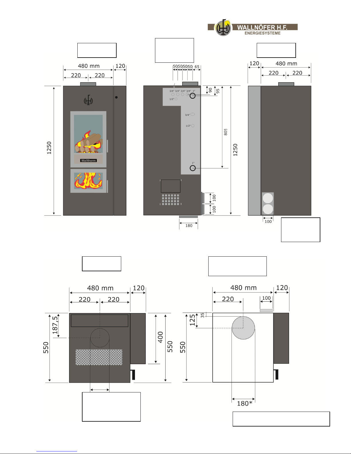
Top view
Front view
View from
right side
Backside
All
dimensions
are in mm
View from under the
stove
Air intake from under the stove
Chimney muff
Page 14
progress & innovation Vers. 12.1 14/46
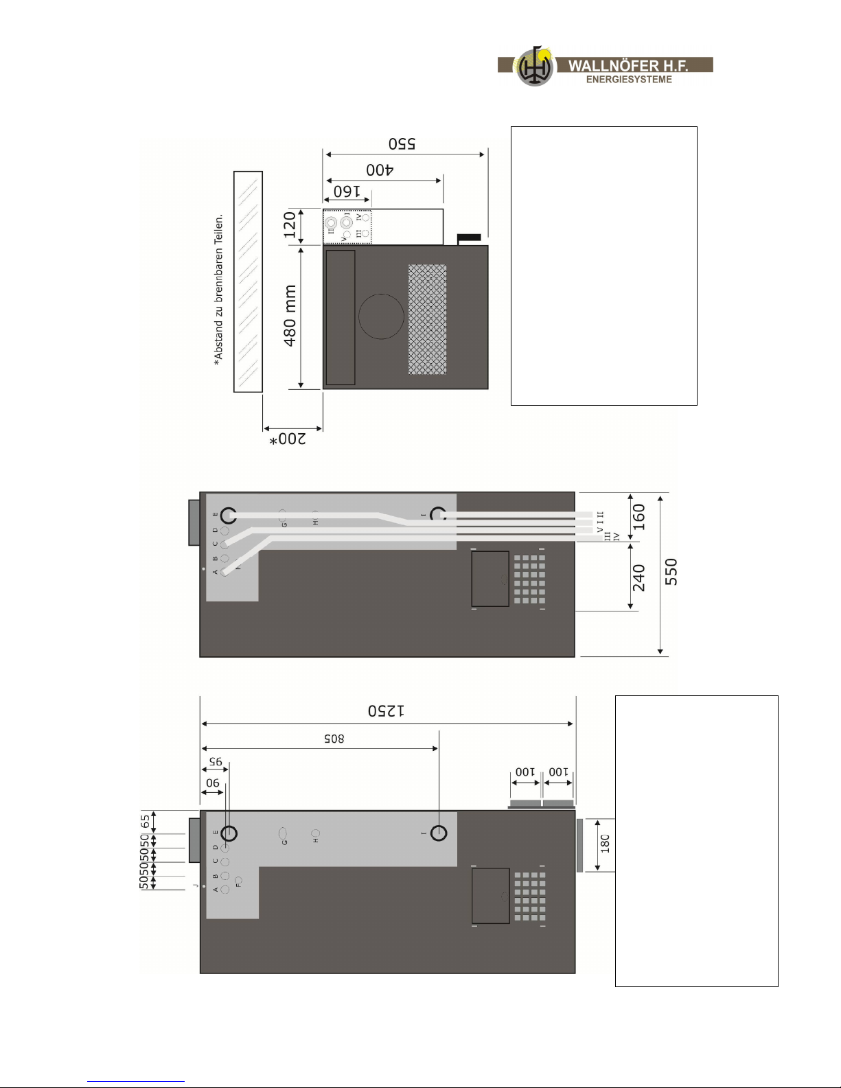
A Security heat exchanger
B Sensor thermal safety drain
C Overpressure valve
D Thermostat(sensor
E Forward flow
F Thermometer
G Thermostat for air intake
H Pressure gauge
I Backflow
J Fume sensor
I Forward flow
II Backflow
III Cold water
IV Drain for thermal safety
V Drain for overpressure valve
Page 15

progress & innovation Vers. 12.1 15/46
!
4. Handling and Transport
The stove is delivered complete with all the parts specified. Pay attention to the stove’s
tendency to oscillate.
Bear the above well in mind when moving the stove on the transport stand.
Make sure the lifting capacity of the lift truck is more than the weight of the
stove. The person manoeuvring the lifting means is held completely
responsible for lifting loads.
5. Preparing the Place of Installation
5.a. Safety precautions
The responsibility for any work done in the space where the stove is to be installed is,
and remains, the users. The user is also entrusted with carrying out the checks regarding
the proposed installation solutions. Stove assembly and dismantling instructions are for
specialized technicians only. It is always advisable for the user to call our assistance
service when they need qualified technicians. If other technicians are called in, please
make sure they are truly qualified.
Before the assembler starts either assembling or dismantling the stove, he must comply
with the following safety precautions:
a) he must not work in adverse conditions;
b) he must be in perfect psychophysical condition to work and ensure that the
individual and personal accident prevention devices are complete, functional and in
perfect working order;
c) he must wear accident prevention gloves;
d) he must wear accident prevention footwear;
e) he must use electrically insulated tools;
f) he must make sure that the load-bearing capacity of the area he is working in for
assembling/dismantling the stove is adequate referring to the stove’s weight.
5.b. Combustion
There are many factors that contribute to good combustion in terms of heat performance
and low emission of polluting substances (co – carbon monoxide).
Some factors depend on the stove itself, where the combustion takes place, while others
depend on the environmental and installation conditions and on the routine maintenance
carried out.
Some of the important factors are:
air for combustion
the quality of pellets used (moisture and size)
features of the combustion products evacuation system
Some indications given in the following paragraphs should be complied with to achieve
maximum stove performance.
5.c. Preparing the place of installation
Page 16
progress & innovation Vers. 12.1 16/46
!
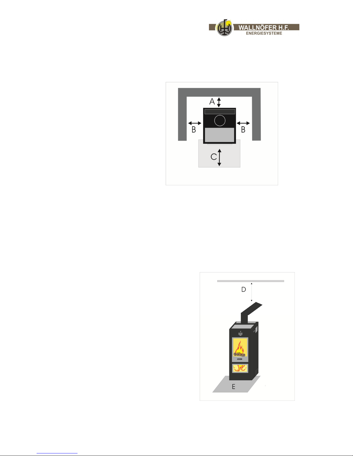
5.c.1. Restriction of space around the stove
The figure below (fig. 5.c.1.) shows the minimum distances to flammable
materials and other items which have to be kept when installing the stove.
a) adjoining wall
b) back wall
c) side wall
d) floor protection
Every item which is eventually flammable has to be protected from the heat. Floors made
of wood or other flammable materials have to be covered with heat-resistant materials
as, for instance, a metal plate of 2-3 mm. The metal plate has to cover the complete part
of the floor in front of the stove.
! Please control the norms valid in the installation country.
5.c.2. Restriction of space above the stove
If there are any beams above the stove and the
chimney hood, they have to be insulated with
heat-resistant material (fig. 5.c.2.).
a) front floor protection 30 – 50 cm
b) side adjoining wall 20 cm
c) upper wall and chimney hood 50 cm
Attention: Leave enough space for eventual maintenance work.
Page 17
progress & innovation Vers. 12.1 17/46
!
!
!
5.c.3. Combustion air
When working, the stoves takes from the room in which he is installed a certain, small
amount of air. Therefore air has to be supplied from outside through an opening to
houses that possess controlled airing and ventilation systems.
In the room where the stove is placed has to be installed an air inlet of 11,5 x 11,5 cm.
The opening of the airing must not be easily closable.
Outside a stable grille must be fixed; on windy and stormy places should a protection
system against rain and wind should be fixed, as well.
Attention: Extractor hoods that are installed in the same room as the stove,
can cause problems.
Attention: If there are other fireplaces near the Walltherm stove,
the combustion air must be obtained from outside.
Danger: The UNI-Norm 10683 forbids air supply from garages, storerooms
where fuel and other materials are kept and rooms where combustible activities
are practiced.
Please obey the laws and norms valid in the installation country.
Combustion air from outside:
If you would like to obtain the combustion air from outside, you can connect
a canal. Follow the right of the installation country!
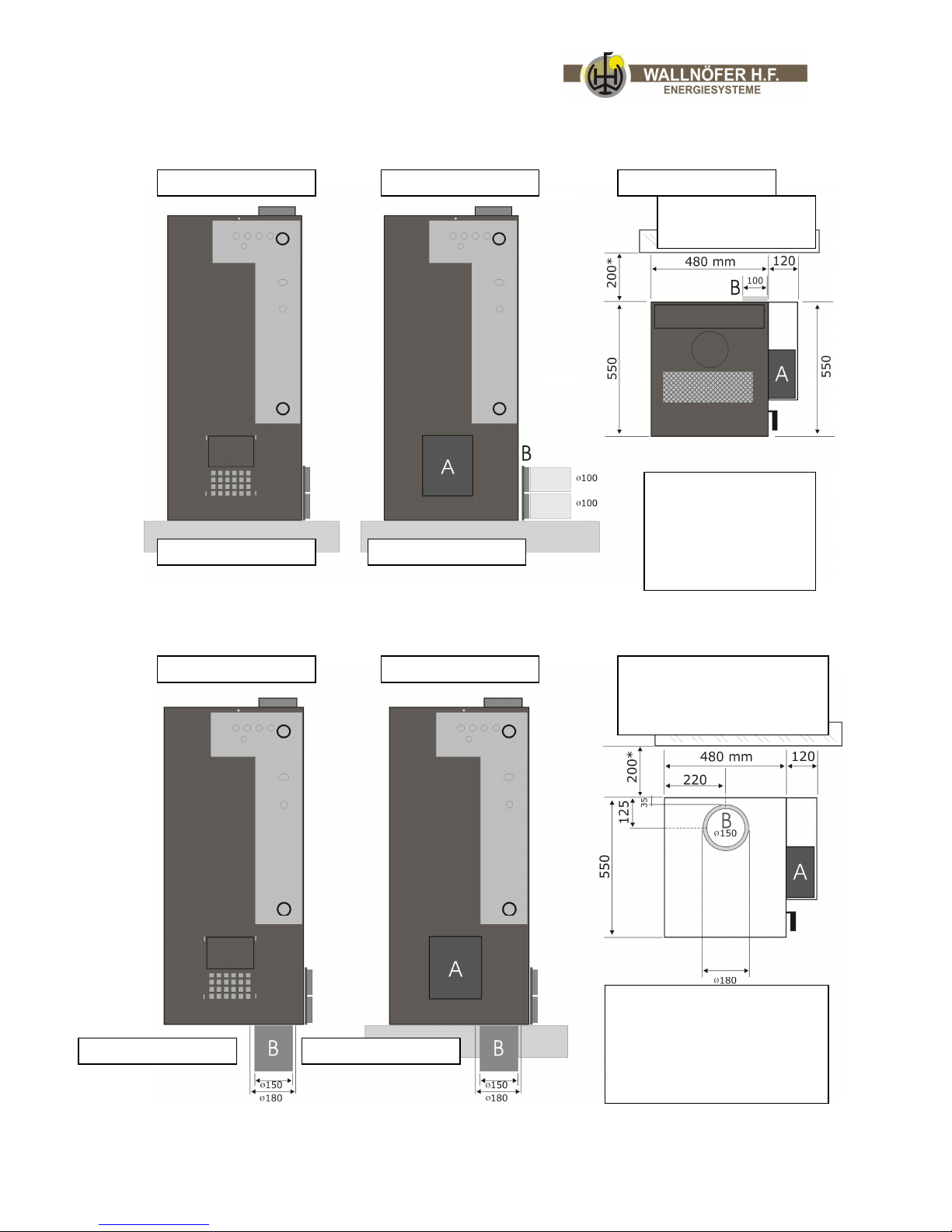
On the Walltherm® we have two possibilities to connect the canal with the external
combustion air:
- On the bottom we have an aperture of Ø 180 mm on which we can connect the canal.
- On the backside we can connect two pipes with a diameter of Ø 100 mm.
In every case it is necessary to add the lateral cap, which is not part of the standard
stove (more details – see pictures next pages)
Info: On the canal you should install a flap, so you can avoid that cold temperature
comes inside the Walltherm when it isn`t operating.
Page 18
progress & innovation Vers. 12.1 18/46
Right
stove side
Right
stove side
Top view
Floor Floor
Maintain distance to
flammable objects!
A external air cover
B Air inlet from the
backside 2 x 100mm
A external air cover
B Air inlet from under the stove
(opening of 180mm, tube needs to
be 150mm)
Right
stove side
Right
stove side
Floor Floor
View from under the stove
Maintain distance to flammable
objects!
Page 19
progress & innovation Vers. 12.1 19/46
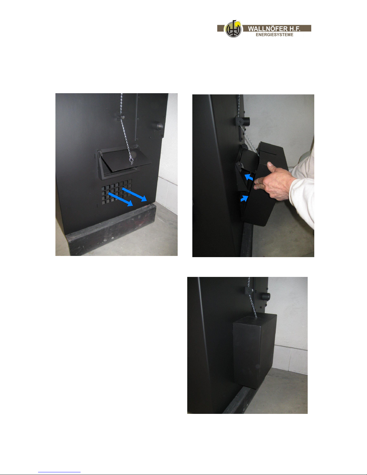
How does the cap for the external air connection work?
The channel for the external air is connected from under the stove or from the backside.
That air enters the lower part of the stove. From there the air exits, as you can
see on the pictures below. If you add the cap to the stove, the air is channeled from the
lower part of the stove into the main air inlet on the right side.
Without cap, the air enters the lower part of the stove If you install the cap, the air is channeled to the
where it can exit through the holes on the side. main entrance of the combustion air.
When the cap is installed, the flap of the
combustion air inlet can be operated
nomally by the automatic fireing controller
throug the chain.
Page 20
progress & innovation Vers. 12.1 20/46
!
!
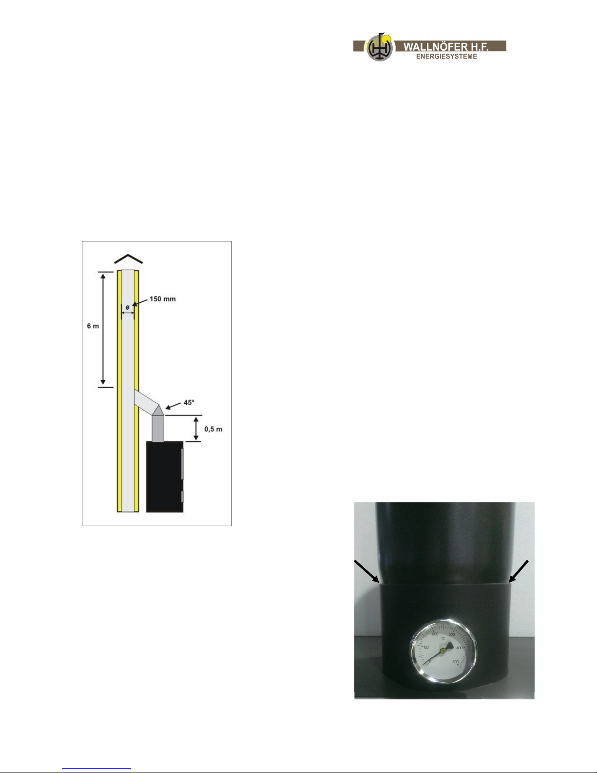
5.c.4. Chimney and exhaust pipe:
Please obey the laws and norms valid in the installation country.
After having found an appropriate place for installing the stove, please try to install the
exhaust pipe, while taking into consideration paragraph 5.c.1. For the smoke outlet use
rigid, varnished steel pipes (min. 1,5 mm) or high-grade steel pipes (min. 0,5 mm) with
15 cm diameter including sealing (to cover distances until 12 m) or 18 cm diameter
including sealing (to cover distances over 12 m).
Attention: For a correctly working drought, the pipe has
to exit the stove vertically for at least 0,5 m before
having the first angle. If possible, the pipe then should
enter the chimney by using a 45° pipe (better drought
than with 90°).
The stove must only be connected to a chimney which is
intended for such a fireplace. Several-time connecting
usually causes problems and malfunctions. The pipes
have to be connected further down together with the
sleeve, so that the smoke and condensation cannot
escape.
It is very important to insulate the chimney pipe with
suitable materials (rock wool) or to use double
insulated steel pipes. If the chimney is not isolated,
the Walltherm will most probably not work!
There should be no horizontal parts in the exhaust
pipe, because it corrupts the drought a lot!
The chimney tube gets inserted into the muff of the
Walltherm stove (see picture).
Page 21

progress & innovation Vers. 12.1 21/46
!
!
!
Danger: The connecting of the exhaust-pipe must not be connected with
the following pipes:
Chimney hoods which are already used for other heating systems (boilers,
heaters, chimneys etc.);
Ventilation systems (extractor hoods, ventilations etc.) even if they are
running separately.
Attention: Due to unfavourable conditions of the extractor hood (several
bends, curves, unsuited chimney etc.) the smoke outlet may not work
optimally. In such a case please contact the technical customer service.
Extractor hood at the exterior/outside wall
Attention: Before installing in residential buildings please contact the
management of the tenement block and ask for permission.
For installation according to the norms please take the following into
consideration:
For the vertical smoke outlet a wind and rain protection chimney must be installed.
To guarantee a correct smoke outlet, the chimney must be away at least 30 cm from the
exterior wall.
In extremely windy areas and on the coast in general please always use a vertical Hchimney.
For installations of pipes outdoor please use double insulated steel pipes (resistant to
weathering) in order to avoid condensation which can cause malfunction of the heater.
Please seal up the opening between wall and pipe.
Deduction on the roof with a “traditionally” chimney hood
Referring to measure and used materials the chimney hood underlies the norms of UNI
9615-9731. The exhaust pipe above a traditional chimney hood should correspond to the
following rules:
to check the chimney hood’s condition; old chimney hoods should be redeveloped
through inserting an isolated steel pipe (with rock wool or vermiculite);
the smoke can only be directly conducted to the chimney hood if the chimney measures
inside at maximum 20 x 20 cm (diameter 20 cm) and if it is equipped with a inspection
flap.
Attention: If the inside of the chimney hood measures more, an isolated steel
pipe (15 cm in diameter) should be inserted.
make sure that the connecting at the chimney is sealed up
please avoid the contact with flammable materials (beams) and
insulate them with heat-resistant materials.
Page 22
progress & innovation Vers. 12.1 22/46
6. Installation
6.a. Levelling of the wood-gasification stove
Please level off the stove with the help of a spirit level.
6.b. Different connections
6.b.1. Electricity connection
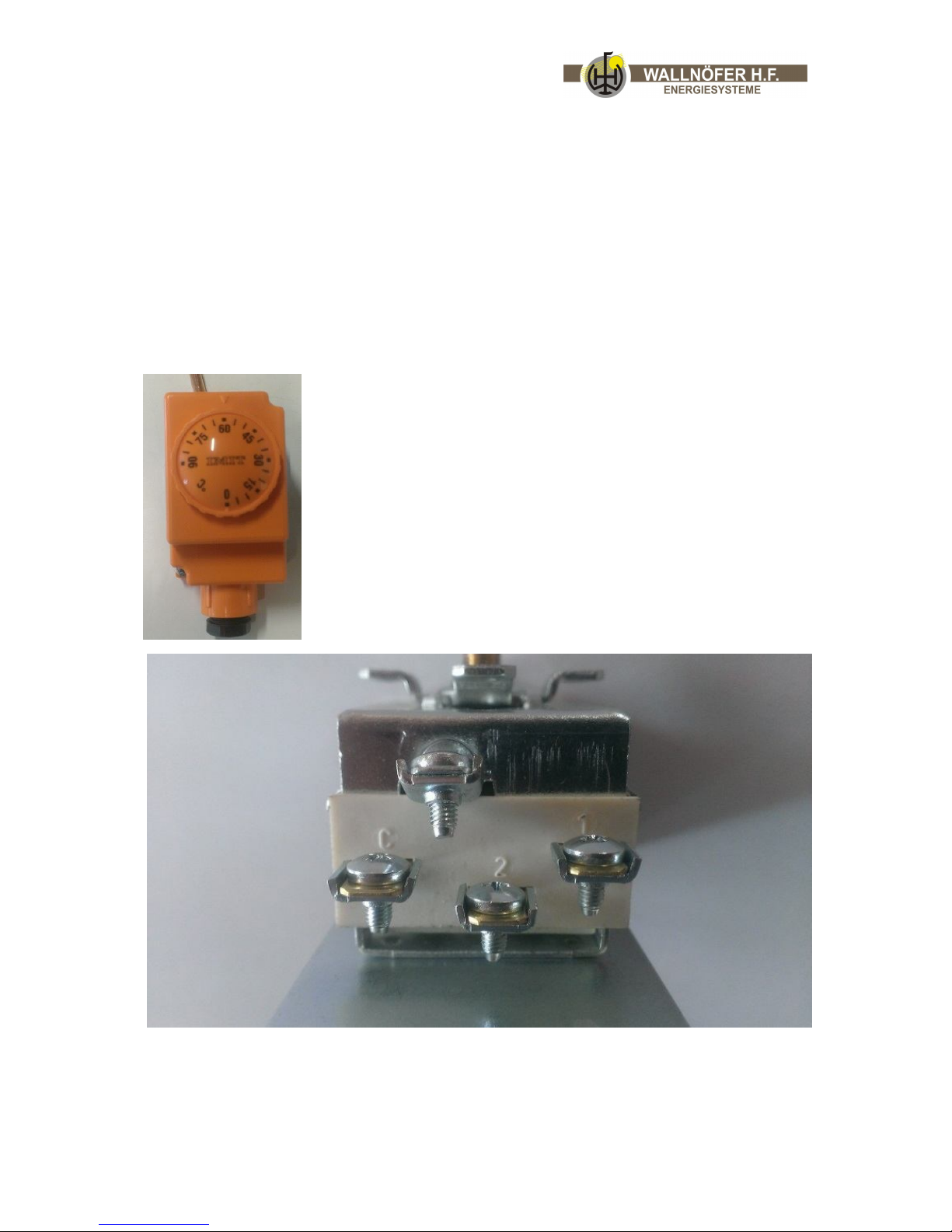
Please connect the thermostat, which was delivered together with the stove, with the
heating pump and through a plug with the electric cable.
The Thermostat needs to be set to at least 60°C!
Inside the thermostat there are 4 connections. You need to connect the junctions C and 2
as well as the ground! The connector 1 remains unused! If you use the WAL02, it is not
necessary to connect the thermostat!
Page 23
progress & innovation Vers. 12.1 23/46
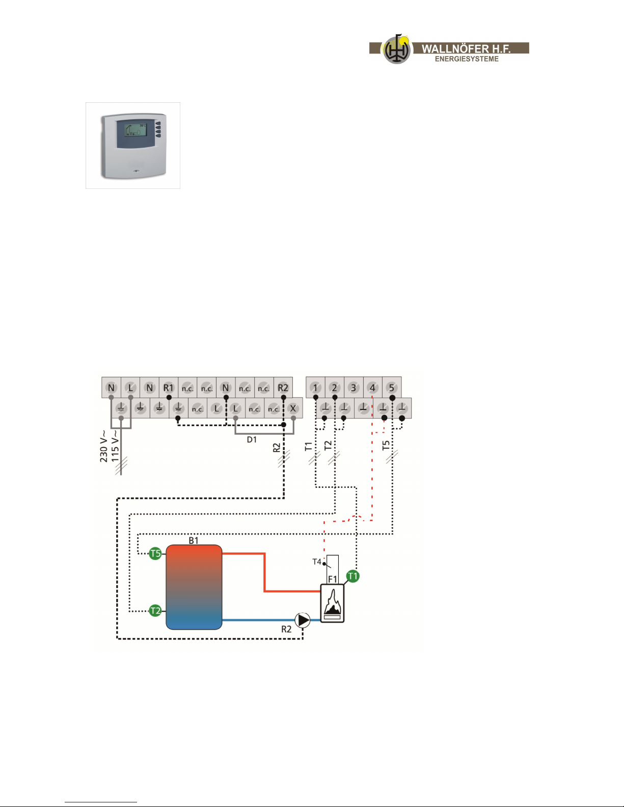
Optional controller:
Instead of the thermostat you can also install the regulation WAL02,
with this regulation you can read the temperatures of the storage
tank, boiler and the solar system directly in the living room. The
regulation WAL02 is also configurated with an ALARMFUNCTION this
function will inform you when you have to close the exhaust fume flap
(5)
WAL02
Digital regulation for the Walltherm® and a solar system:
- regulation for the Walltherm with minimum temp.
- with Alarmfunction* for the Walltherm
- wit modulating pump control (solar system)
- with 2 sensor PT 1000
- with 1 sensor for the exhaust gasses
- with display for observation of the different temperatures: boiler temp., exhaust gas
temp., temp. of storage tank and temp. in the solar panels.
Wiring of the Walltherm:
B1 – Storage tank
F1 – Walltherm stove
R2 – Stove pump
T1 – Sensor for water temperature in the stove
T2 – Sensor for tank temperature (inferior part)
T4 – Sensor for exhaust fume temperatures
T5 – Sensor for tank temperature (upper part)
Page 24
progress & innovation Vers. 12.1 24/46
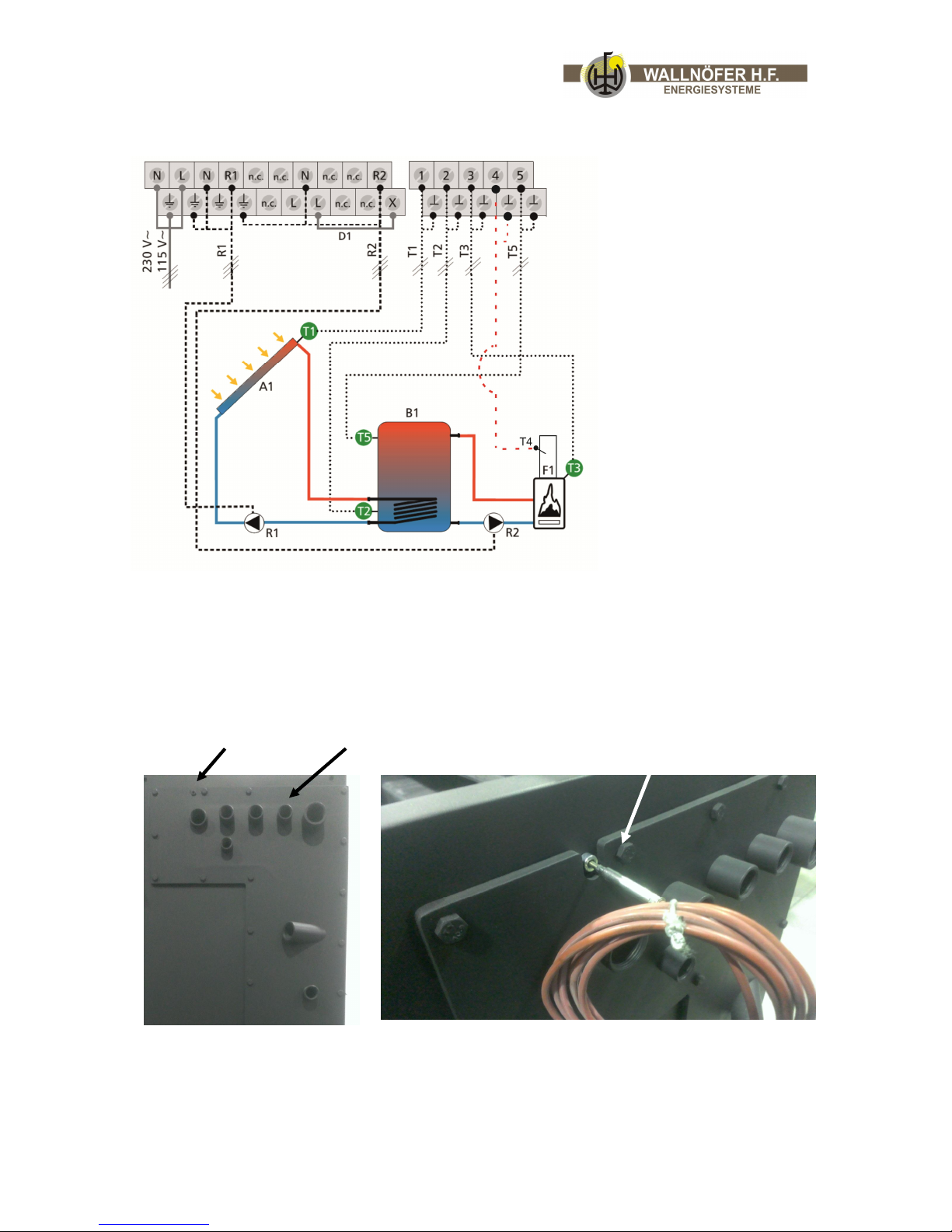
Wiring of Walltherm and solar plant:
A1 – Solar plant
B1 – Water tank
F1 – Walltherm stove
R1 – Solar pump
R2 – Stove pump
T1 – Sensor for solar plant
T2 – Sensor for tank
temperature (inferior part)
T3 – Sensor for water
temperature in the stove
T4 – Sensor for exhaust fume
temperature
T5 – Sensor for tank
temperature (upper part)
Alarmfunction: Often, clients forget to close the exhaust fume flap (5) in time, to
avoid it we configurated the regulation WAL02 with an ALARMFUNCTION. Always
when the temperaturer of the exhaust gasses are reaching 300 °C you will hear
an acoustic alarm signal, this will remember you to close the fume flap.
Info: The sensor for the exhaust gasses (ALARMFUNCTION) can be mountend on the
right side. Look pictures below.
Sleeve for fume sensor water sensor
fume sensor
Page 25

progress & innovation Vers. 12.1 25/46
!
Earthing
Danger: The system must be earthed and fitted with a circuit
breaker as provided for by current laws (fig. circuit diagram).
6.c. Important indications
6.c.1. The doors
The boiler must never be operated with open doors. Eventually out coming glowing
materials can cause fire.
Before opening the doors please open the exhaust fume flap so the smoke is taken up
gradually through the flue and cannot escape through the door. The doors should only be
opened when the fire turns out and you want to put some more wood on it. If you have
to open the doors during the burning phase please try to do so very slowly and carefully.
Sparks and fire can possibly come out.
Again, do not forget to close the fume flap (5)
6.c.2. Thermal safety drain
The thermal safety drain ability to operate must be periodically checked by a heating
expert.
6.c.3. Circulating pump
The circulating pump should work once a month for about 1 minute during the heatingfree period of time. Through reducing the temperature at the thermostat (e.g. to 10° C)
this helps to avoid that the pump gets stuck.
6.c.4. Density
Please check the density of all doors. There should be no out coming of smoke in order to
avoid that smouldering gases can reach your living room. If the doors let in draught,
please change the sealing.
6.c.5. Permissible limiting temperatures
boiler – working temperature maximum 80° C
boiler – declining temperature minimum 60° C
These limiting values must never be overstepped nor undercut during the working phase.
Continuous undercutting endangers the stove’s working life and the supplier’s guarantee
lapses.
Page 26
progress & innovation Vers. 12.1 26/46
6.c.6. Cleaning
The stove requires frequent and thorough clean and periodical inspection to guarantee it
will work properly and to ensure constant heat efficiency. Use a vacuum cleaner to
remove all the ash (when it is cold) that has collected in the stove.
7. Using the stove - lighting
(fig. 3.a.1. – 3.a.5. chapter: 3.a. Spare parts/components)
7.a. Control
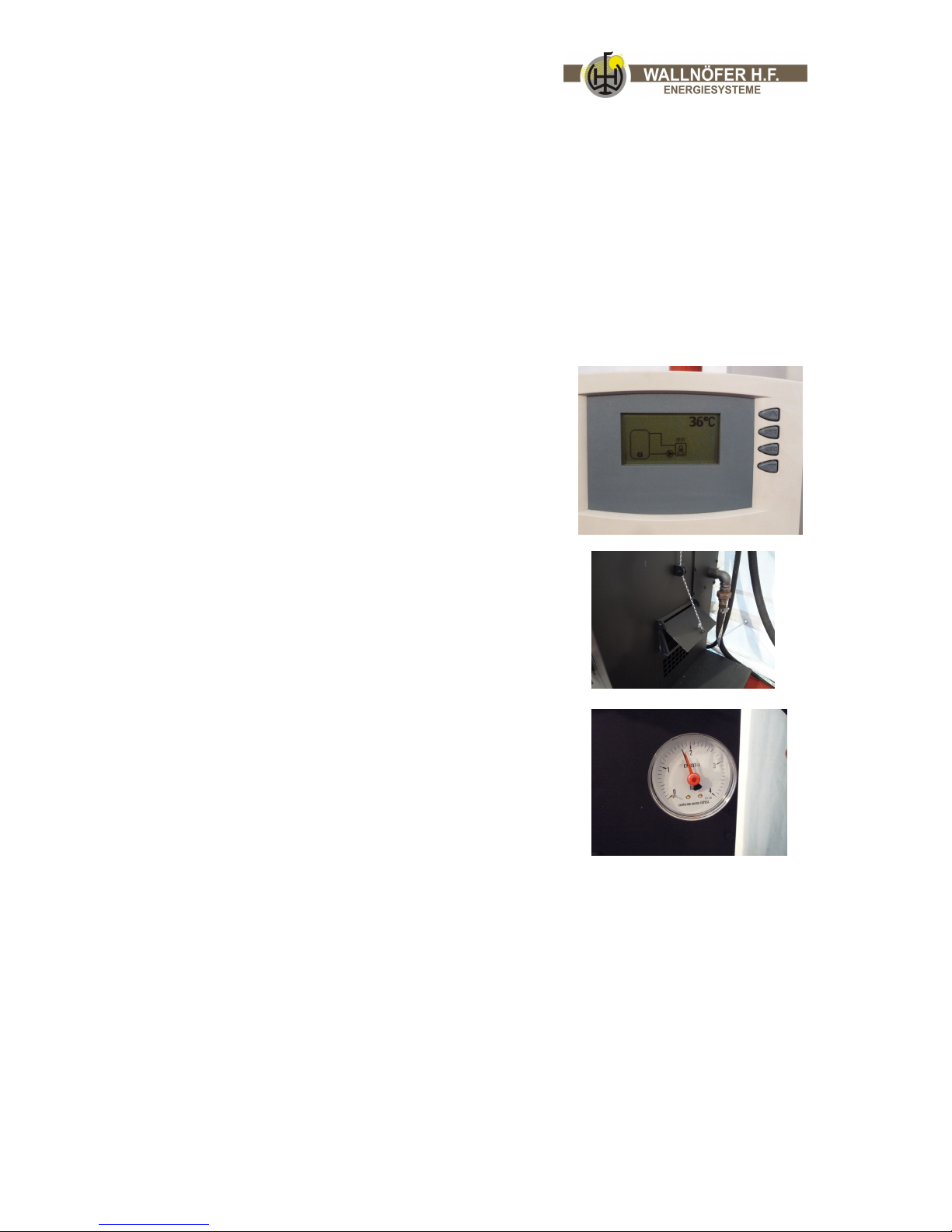
Check the temperature of the storage tank! Is it
already hot or can the stove be lighted?
Are eventually existing levers to the flow pipe open?
Can enough fresh air (combustion air) reach the
living room?
Is the thermostatically controlled flap (6a, see
picture) for the air inlet open?
Is there an open expansion or a closed expansion
container with 1,5 bar pressure and enough volume
(for 1.000 litres store about 60 litres)?
Is the safety valve (3 bar opening pressure) through
an outlet pipe with the drain connected?
Is the thermal safety drain with the sanitation water
pipe and the outlet pipe connected?
Is the water pump and the pump’s control (thermostat
with about 65° C – adjustment or difference regulation
of the temperature 6° C ▲T) connected?
Tip: test it with low temperatures!
Is the water store filled with water and ventilated? (no
noises of the pump)
Is the rotary top at the 3-ways-thermo-valve (7)
open? (the flow can be set; at the beginning please
open it completely)
Is the glass of both doors clean? Clean the glass with a
damp cloth, newsprint or a damp paper rubbed in
ashes.
The rust slits, the air entrance openings, the nozzles
and the lower combustion chamber must be free from ashes. Insert the angular
shovel into the lower combustion chamber and use a little brush in order to sweep the
ashes off the grill. Sweep the ashes to the openings of the nozzles where they can fall
into the shovel. Please eventually spread the charcoals on the grill.
The fume flap (5) for the direct flue outlet must be completely open after the lighting.
(Function: lever in horizontal position = flap closed; lever pointing down = flap
opened).
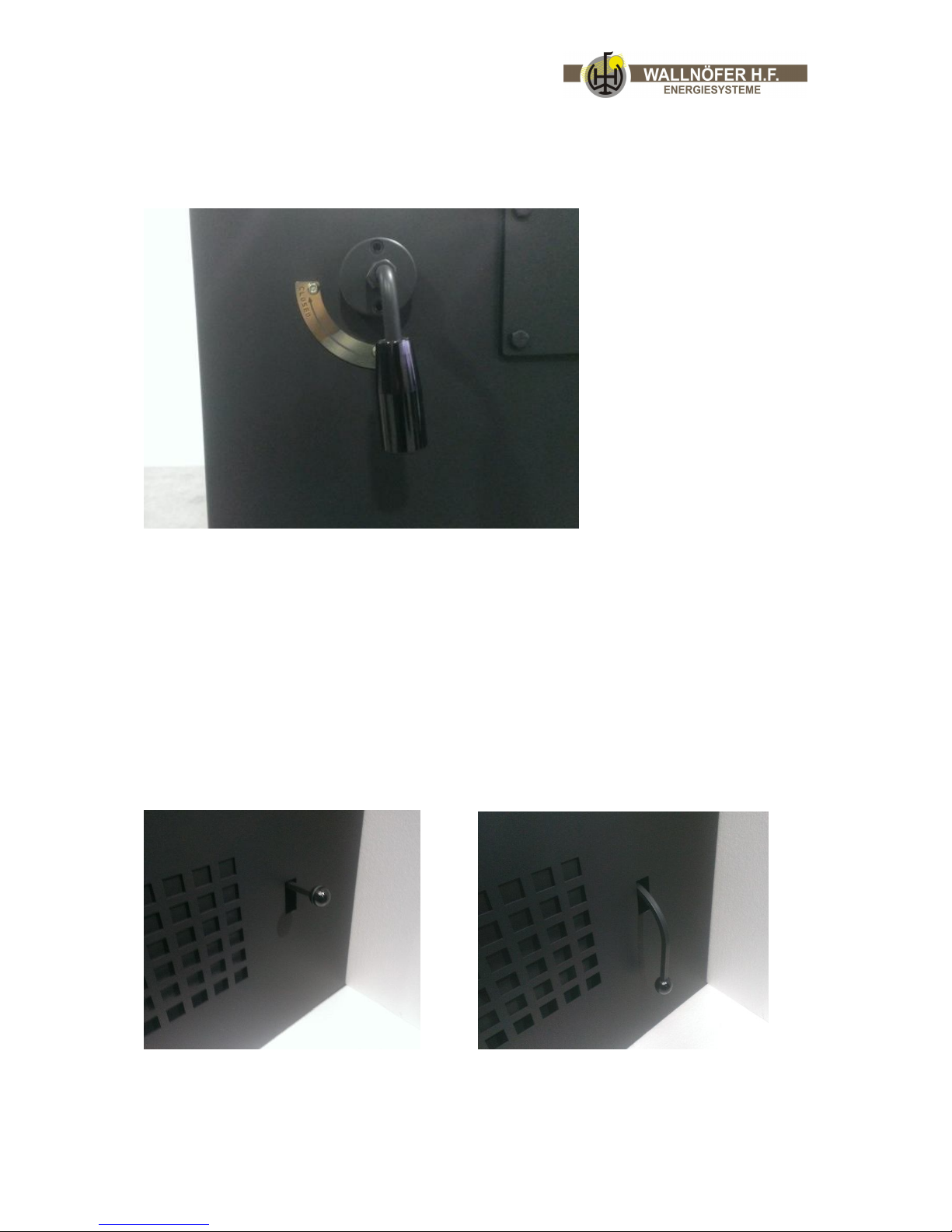
The secondary air slide bar (2a) should be slightly opened for the lighting. (lever to
the back = slide valve closed; leaver closed = no secondary air; lever to the front =
slide valve opened = secondary air intake open).
Page 27
progress & innovation Vers. 12.1 27/46
7.b. Lighting phase
Before the lighting the turn flap/lever (5) must be opened for the exhaust switch
over (lever pointing down) that the smoke is taken up gradually through the flue.
Attention: Do not leave the exhaust fume flap opened constantly, the
opened possition is only used to heat the stove up at the beginning.
Please close the flap completely after the heating phase.
If you channel the intake air to the stove by an air channel then you can optionally
decide to use a air intake cover with an integrated flap. If the stove isn´t burning you
can close this flap to prevent cold air from flowing through the stove and out of the
chimney. If you are using this air cover with the flap, make sure to open the flap before
you light the stove.
Flap opened Flap closed
Page 28
progress & innovation Vers. 12.1 28/46
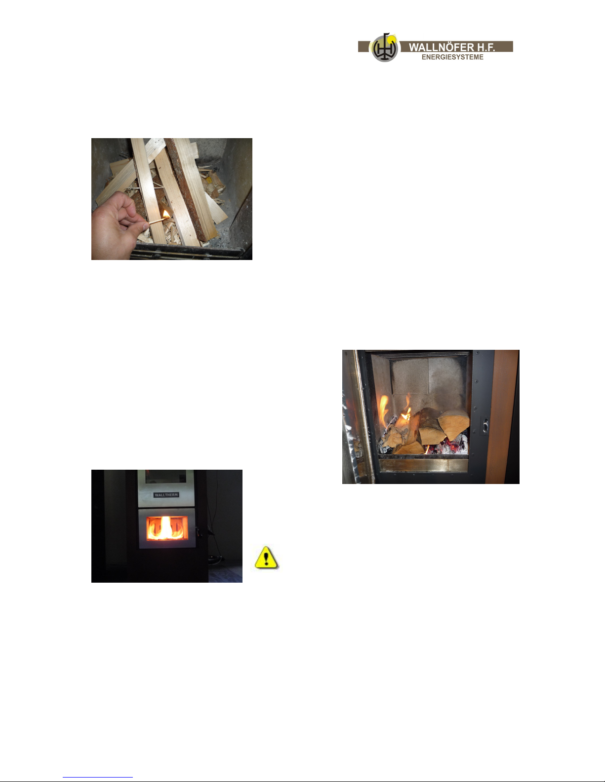
Spread on the two grills of the filling chamber (upper combustion chamber) about 5-6
sheets of crumpled newsprint (please begin at the front). Do not use cardboard. Then
spread highly inflammable kindling (again begin at the front) over the complete width of
the grill (quantity/amount: about 200 grams softwood or about 500 grams hardwood).
Then spread thin logs of wood (we recommend beech
wood) horizontally and over the complete width of
the grill.
Now you can ligth the fire and you should
wait until it sets up the necessary embers (2- 3 cm)
in the upper combustion chamber, the embers has to
cover the grill completely (this takes about 30
minutes).
Then spread thin logs of wood (we recommend beech wood) horizontally and over the
complete width of the grill.
Afterwards fill the combustion chamber with wood (length of the logs max. 35 cm). The
wood should follow on easily. Please try to avoid hollow spaces.
Wait until the stove and the chimney have warmed
up (300-350° C exhaust temp.) and have enough
draught. Then you can close the exhaust fume flap
(5) for the direct smoke outlet.
The flame is now burning in the lower combustion
chamber.
Please insert only as much wood as the warmth store is
able to take up and to convert into energy.
If you want to insert more combustibles into
the stove, make sure the exhaust fume flap is
closed, otherwise smoke exits the door.
Page 29
progress & innovation Vers. 12.1 29/46
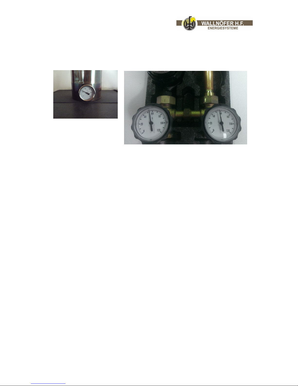
If the Walltherm® works correct you will see the following conditions:
a) the gasification flame remains visible
b) the temperature of the exhaust gases dropes down to 120 -150 °C
c) the temperature on the reverse flow (pump group) grows to 60 – 75 °C.
Page 30
progress & innovation Vers. 12.1 30/46
Inside the stove:
The hot wood gases now draw/pass through the combustion jets into the lower gas
combustion tunnel 3, are supplied with secondary air at the injector block 2, and then
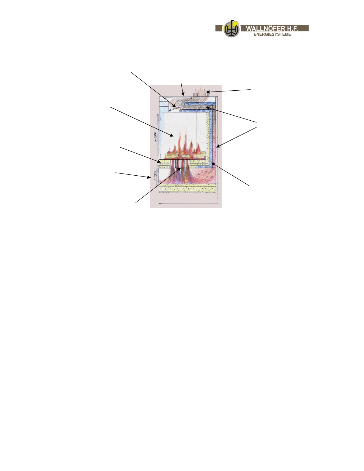
burn at high temperature. With the help of the secondary air slide bar 2a set the
desired after-burning. The hot exhaust pours out of the tunnel 3 and into the gas
fissure in the back wall, and flow around another water bag into the stove pipe flange
4a. On the way to the top they heat the heating water in the boiler 8. The boiler
which is fit to the stove’s back wall is heated on both sides, from the front by the
upper combustion chamber and from the back by the hot exhaust of the smoke
channels 4. Through the glass door to the upper combustion chamber 10 and the
door to the lower combustion chamber 3a the burning process in the upper
combustion chamber 1 and in the gas combustion tunnel 3 can be controlled.
If the draught is weather-related or chimney-related wear/poor it can be increased
through a brief opening of the fume flap for exhaust switchover 5. Here for please
bring the lever 5 into a pointing down position. If the fume flap is slightly open the
result is a good visible upper and lower fire that guarantees a special effect.
The stove reaches most efficiency in combination with a store when the upper
combustion chamber is completely filled with wood of high quality.
The air which is needed for the combustion is sucked in by the air inlet with
thermostatically controlled flap (on the stove’s side) 6a, first reaches the combustion
air intake channel 6, and then the safety thermostat for control of combustion air
intake 6b which has an air outlet slit towards the glass on it’s underside. Underneath
the glass door the canal flows into a lower diagonal canal 6c with slit toward the glass
and under the combustion chamber’s grill.
Furthermore, the stove has a small cooking plate 9 on which you can cook small
portions of food. If you remove this plate you can clean the flue outlet. Before
cooking please remove the top under the cooking plate (if removing the plate).
(1) Upper combustion
chamber
(3) Lower
combustion
chamber
Combustion jets (2)
(8)
boiler
(4a)
stove pipe
muff
Smoke chamber
(9)
cooking plate
Exhaust fume flap (5)
(2a)
secondary air slide bar
(4
) (10)
3a)
Page 31
progress & innovation Vers. 12.1 31/46
7.c. Loading the fuel
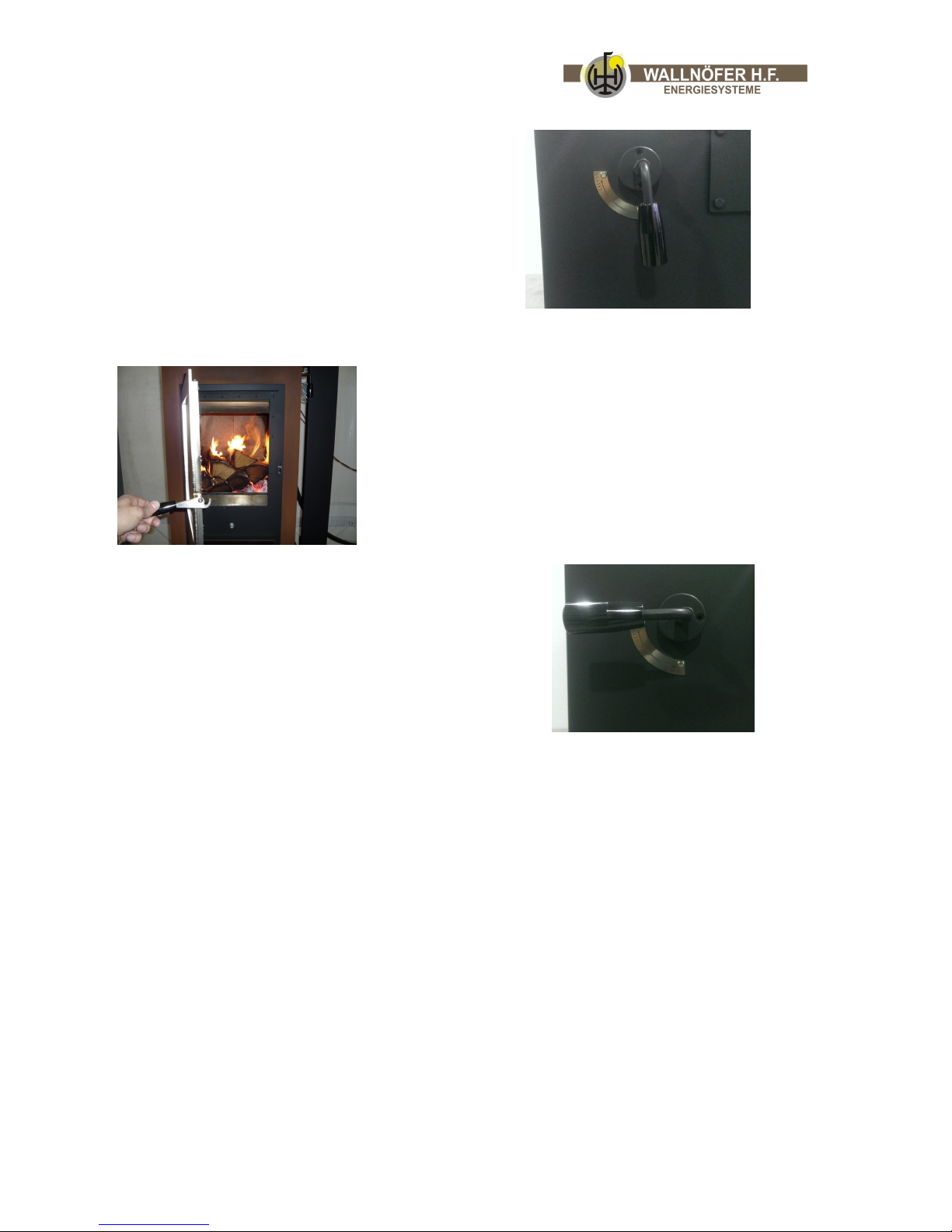
Only open the door of the upper combustion
chamber after the wood has burned off and
changed into embers.
Before putting some more wood on the fire
please open the fume flap (5) (lever pointing
down), wait a second, and then slowly open
the door. Spread out the remaining embers
with the poker and set free the nozzles.
opened exhaus fume flap
Pile up thin logs of wood (in horizontal position) in the
complete combustion chamber.
Burning duration if the combustion chamber is
completely filled about 3 hours for softwood and 4-5
hours for hardwood.
The stove perfectly works if the combustion chamber is
either completely or partly filled (until the upper border
of the door).
Before filling the combustion chamber the temperature
of the store should be checked in order to control how
much energy the store is able to take in/receive.
After putting wood on the fire please close the
fume flap (5) (lever in horizontal position).
closed exhaust fume flap
Page 32
progress & innovation Vers. 12.1 32/46
How to set up the secondary air:
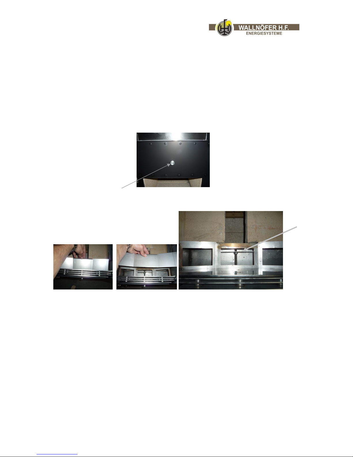
By turning the round stainless steel knob directly between the upper and the
lower combustion chamber, you can adjust the amount of air which enters the
injector block of the stove.
- Attention: Mostly this doesn´t change the visual appearance of the flame!
Adjusting the secondary air:
Turn left = open the secondary air
Turn right = close the secondary air
To see the actual opening of the secondary air – flap you need to remove a cover that is
behind the door in the upper combustion chamber. Then you can see the threated rod
which operates the flap. The flap should be opened by 2 – 3 mm.
You can change the secondary air opening bt only if you have problems with the correct
combustion, otherwise, please leave it like that.
Possible solutions if you have problems with the stove:
The wood in the upper combustion chamber does not cover the complete grill or is
burned off. (It also needs to be layed in one direction, not criss-cross!)
The drought is too weak (min. 12-15Pa, see chapter 5.c.4)
The reverse running temperature of the heating water in the stove is too low, lower
than 60° C - check the thermometer’s display (Pos. Between pump and RR-entrance).
The reverse running temperature can be increased by opening the thermostatically
controlled 4-way valve set (7) for the circulation.
Opening of
secondary air
2- 3 mm.
Page 33
progress & innovation Vers. 12.1 33/46
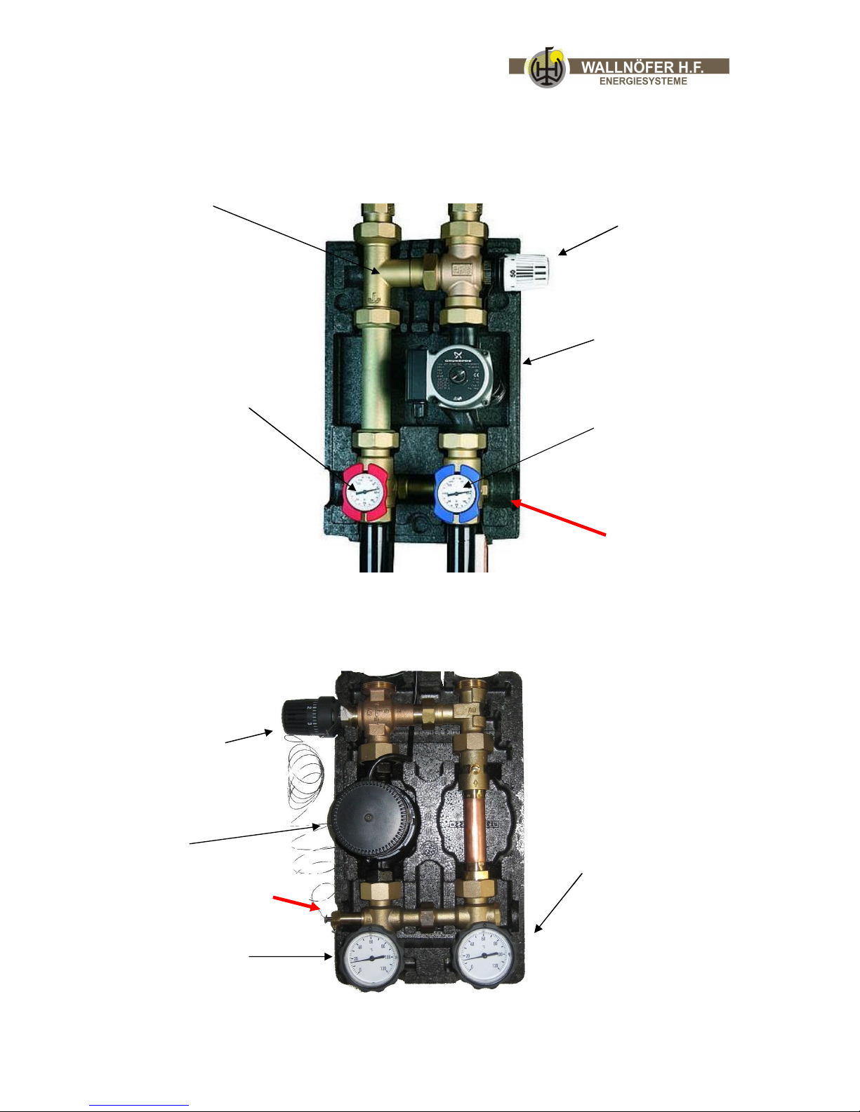
C) The pump group
We add one of the following pump groups to the stove:
Temperature of the
forward flow
Pump
Forward flow stove Reverse flow stove
Positioning of
thermal sensor
Thermal
valve
,
set t
o
at
least 60°C
Deaerator
Thermal valve, set to at
least pos. 6
Positioning of
thermal sensor
Pump
Reverse flow stove Forward flow stove
Reverse flow Forward flow
storage tank storage tank
Temp
erature of the
reverse flow (must be at
least 60°C)
Temperature of the
forward flow
Forward flow Reverse flow
storage tank storage tank
Temp
erature of the
reverse flow (must
be at least 60°C)
Page 34
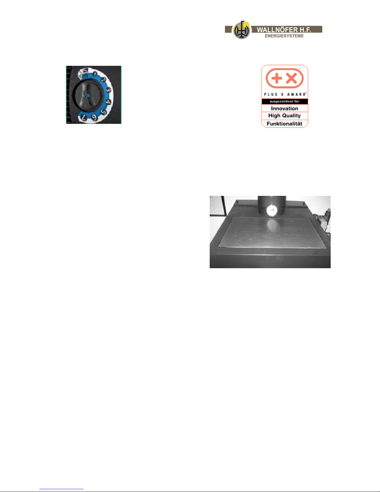
progress & innovation Vers. 12.1 34/46
High efficiency pump Ecocirc:
- max. power 23 Watt
- Spinning the lever on the pump to 0 will
change the backlight color and the
operating mode of the pump
- For use with the walltherm the pump
should be in standard mode where the
LED is white, not blue!
Lever
White LED = manual control of the pump speed
Blue LED = automatic pump speed control by differential pressure
Information to the exhaust gas temperature:
Normally the exhaust gases of the Walltherm®
reach a temperature of around 120 – 150 °C.
Because of this low exhaust temperatures, a lot
of people are worried about problems with the
chimney.
These worries are unjustified: When you light
the fire, the exhaust fume flap 5 is open and
really hot exhaust gases enter the chimney. In
this phase the temperature reaches 200 – 400 °C
and the chimney will dry out and warm up.
After this phase, as soon as the chimney is warm, you can close the flap (5) and the
temperature of the exhaust gasses will lower to 120 – 150 °C. Thanks to the perfect
combustion, the exhausts are really clean and will not cause problems inside the
chimney.
When the exhaust temperature sinks lower than 110 °C, this is a sign that the drought is
too low, please change the following:
Open the cover which is behind the chimney exit on the top of the stove.
This gives you the possibility to create a by-pass for the exhaust gases.
Please see the description below how to activate this by-pass, as a result, a part of the
heat exchanger is deactivated and as a result the exhaust temperatures rise by 10-20°C.
Page 35

progress & innovation Vers. 12.1 35/46
7.d. Permissible and suitable fuels
Important preconditions:
The fuels’ water content should be maximum 20 %.
The firewood has to be dry. The natural drying process lasts 1 ½ - 2 ½ years. This
process can occur outdoors (covered up) and should be continued in an appropriate shed.
The Walltherm boiler is totally planned as wood boiler and is therefore for the following
types of wood particularly suitable:
Guideline for the storage
chopped hardwood: max. Ø 8 cm hardwood: 2 – 2 ½ years
chopped softwood: max. Ø 8 cm softwood: 1 ½ - 2 years
length of the wood: max. 35 cm
Attention: Wood which is still damp and has not been stored long enough
reaches only the half of its real calorific value!
Indication: The stove also works when constantly burning.
In small quantities you can also use woodchips (maximum water content 25 %)
Pressed wood/briquettes of shaving wood which are not produced with binders, if 50
% log of wood are added. Therefore the proportion of pressed wood can be 50 %.
The boiler is only for the combustion of the above mentioned wood fuels and
combinations suited. For the use of other fuels we do not take any responsibility for the
boiler’s function and working life.
The burning of garbage and painted wood or wood which has a
coat of halogen is forbidden. These chemical compounds can cause
highly toxic exhaust fumes and corrosion damages in the heat
exchanger.
Please notice!
Fuels which you must not burn:
free sawdust, hard/glance coal, coke
wood garbage with a coat of synthetic material/plastic
all sorts of garbage
anything that creates acids or other toxics when burning
Page 36
progress & innovation Vers. 12.1 36/46
8. Maintenance and cleaning
8.a. Safety precautions
Prior to embarking on any maintenance work the following precautions must be taken:
a) Make sure all parts of the stove are cold.
b) Make sure the ashes are completely cold and not burning.
c) Use the individual protective gear as established by the EEC directive 89/391.
d) Check that the main line switch is off (if an electrical thermostat is used).
e) Make sure that the power supply cannot be switched on accidentally. Take the plug
out of the wall socket.
f) Do not remove or disconnect parts of the water pipes if they are under pressure.
g) Always use the most appropriate maintenance tools.
h) Once the maintenance or repair work is finished reinstall all the protections and
reactivate all the safety devices before switching the stove back on.
8.b. Routine maintenance (for the user)
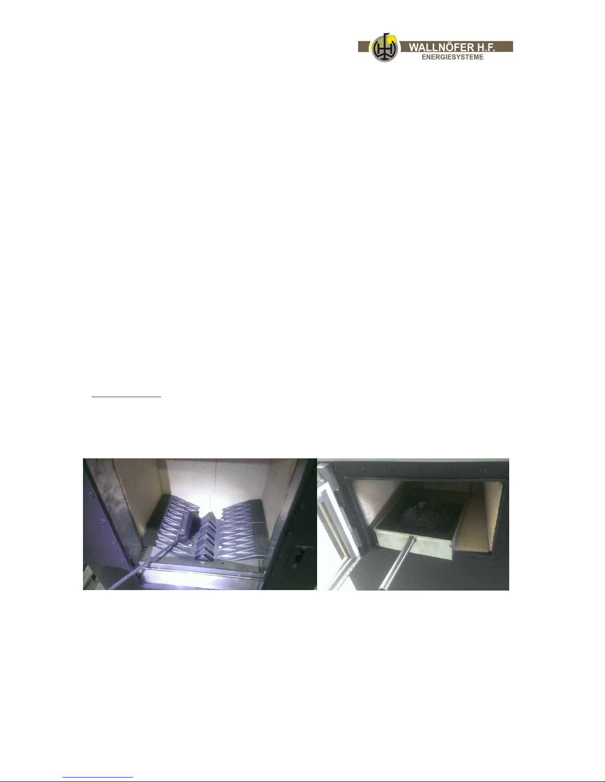
8.b.1. Cleaning the stove
The stove requires a simple but frequent and thorough clean to guarantee it will work
properly and to ensure constant heat efficiency.
Daily cleaning:
Remove all the ash that has collected on the grid. Insert the angular shovel into the
lower combustion chamber and use a little brush to sweep the ash off the grid in the
upper combustion chamber. Sweep the ash to the openings of the injector block where it
can fall into the shovel. Remove the shovel with the ash and empty it.
Page 37
progress & innovation Vers. 12.1 37/46
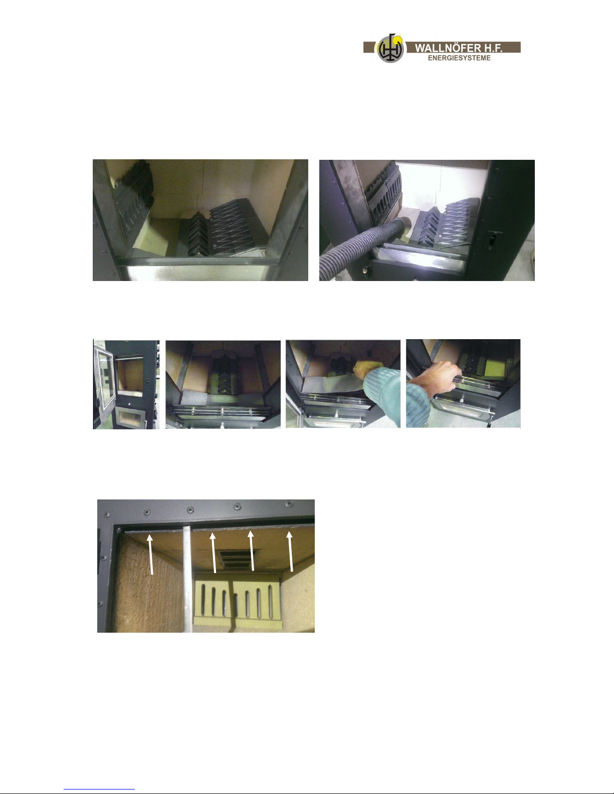
Periodical cleaning:
There are two little ash boxes under the two stair grids. Please lightly lift the grids on the
side of the jets and clean them. This is very easy when using a ash vacuum cleaner. This
should be done every 2 weeks.
To prevent the glass from the upper combustion chamber to get black you need to clean
the air inlet which is right behind the upper door (stainless steel grill, see pictures below)
Also clean the gap in between the door and the refractory stones in the lower combustion
chamber with any flat object. If this gap is not cleaned properly there is no airflow
coming down through it from above and the glass of the lower door is not cooled.
Page 38
progress & innovation Vers. 12.1 38/46
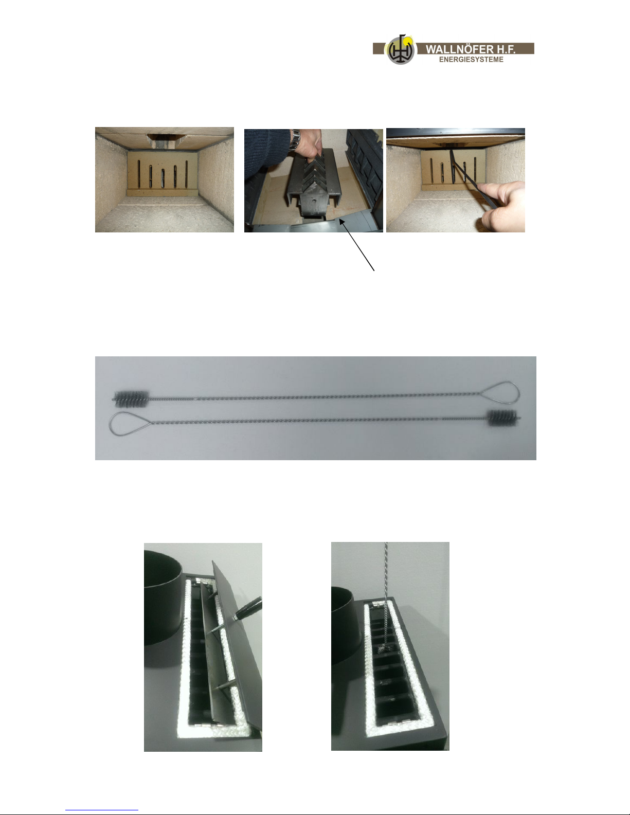
Also the grid in the lower combustion chamber and the injector block needs to be
cleaned. To get the grid out, you need to lift the injector block!
Grid Injector block
Monthly cleaning:
The smoke channels should be cleaned every 6 – 8 weeks. For cleaning the smoke
channels please use the two brushes delivered with the stove.
Cleaning the smoke channels
To clean the smoke channels, remove the top cover behind the exhaust fume muff on top
of the stove, then you see the heat exchanger.
Hole on the front needs to point to the door
Page 39

progress & innovation Vers. 12.1 39/46
Clean all channels with the long brushes!
Important: Every brush must hit the bottom of the lower combustion chamber to make
sure every channel is completely cleaned! Repeat until the channels are free of ash
remnants.
After cleaning the lower combustion chamber set in the grid on the right position.
Please make shure the injector block is clean, otherwhise it could influence the drought!
Make shure to insert the injector block with the hole on the front side pointing towards
the front door.
8.b.2. Cleaning the glass
Clean the glass with a damp cloth, newsprint, or damp paper rubbed in ashes. You can
also use ordinary oven cleaners. Do not clean the glass while the stove is working and do
not use abrasive sponges.
8.b.2. Cleaning the flue
This should be done at least twice a year at the beginning and halfway through the
winter season. In case of horizontal flues please remove all ash and soot deposits before
they have the chance to clog the smoke passage.
Measures in case of fire in the flue:
Close the fume flap 5 (leaver in horizontal position). Close the air inlet with
thermostatically controlled flap 6a (turn the thermostat button to the right until the flap
is closed).
Page 40
progress & innovation Vers. 12.1 40/46
8.b.4. Controlling the sealing
The sealing of the doors (upper and lower combustion chamber), the cooking plate (9),
the opening with lid for access to smoke channels (4c) and the fume flap for exhaust
switchover (5) must be checked yearly. If necessary, they have to be changed and at all
events replaced every two years.
9 Recognizing errors and taking measures against faults
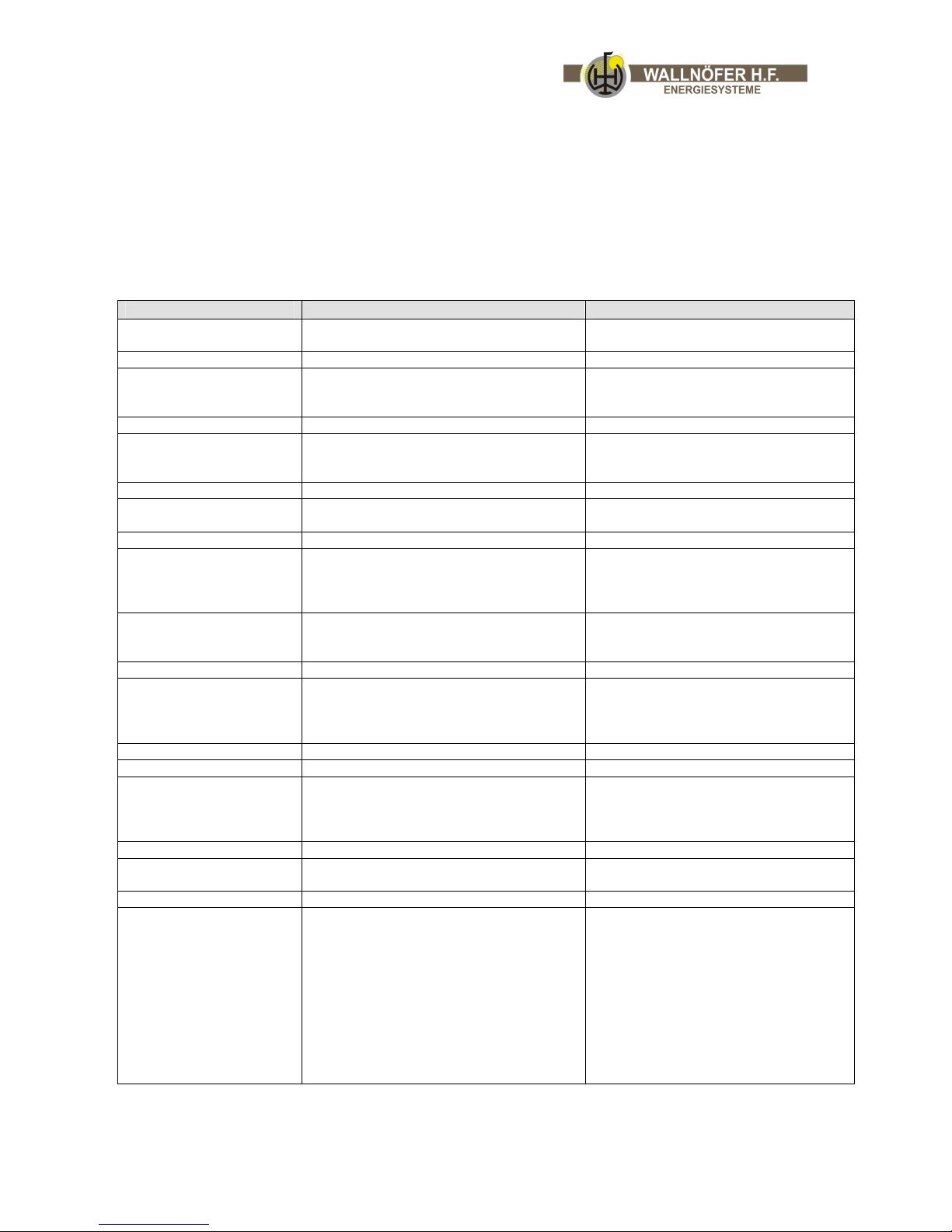
ERROR POSSIBLE CAUSE MEASURE
Very high exhaust
temperature >200° C
Exhaust fume flap 5 opened Close flap 5
The fire goes out
because air regulator
closes the air inlet 6a.
This could happen due to a too high
temperature of the store
(return temperature)
Please light the fire only if the
warmth store is able to take up
energy/warmth.
The pump does not work (power cut). Make sure that electricity is available.
If the pump does not work, check the
setting of the thermostat. The starting
temperature may be too high.
Set the starting temperature between
50° C and 60° C.
No circulation, air in the system. Ventilate the system.
Too less pressure.
Check the pressure and if necessary
increase to at least 1,5 bar.
Smell/stench in the
living room
Sailing leaking.
Check the sealing of the doors 10 and
3a, the cooking plate 9 and the
opening with lid 4c and replace them
if necessary.
Too low/poor draught.
Measure the draught and if necessary
reinforce it with a longer flue pipe or
an exhaust blower (at least 12 Pa).
Noises in the heat
exchanger
Air in the pipe.
Ventilate the pipe and set the
pressure at 1,5 bar (at least).
Steam in the heat exchanger. Check if the pump is circulating.
The flame in the upper
combustion chamber
continuously goes out.
Too low temperature on the reverse
flow
Check the temperature of the reverse
flow (pump group), the temperature
has to be on
min 60° C.
Too low/poor draught. Measure the draught, > 12 Pa.
False air above/over door with glass 3a.
Check the sealing and if necessary
change it.
Power cut while the
stove is working.
Keep calm, do not load more wood,
the safety fittings come into force. As
soon as the electricity is back, please
check the following:
A) pressure, at least 1,5 bar
B) ventilate the system
C) check the pump (set the
thermostat at 0° C and check if
the pump starts to work,
afterwards set it again at 60° C)
Page 41

progress & innovation Vers. 12.1 41/46
10. Saving energy
The temperatures of the rooms and how long the stove works represent great influences
on the consumption of fuels.
1° C lower room temperature can effect an economizing/saving of fuels up to 6 %.
Therefore please notice the following:
Try to avoid room temperatures which are higher than 20° C and set you heating
system appropriate.
It is worthwhile to switch off the radiators in unused room, as long as there is no
danger of frost which can cause damp damages concerning the building and the
furnishings.
In the main inhabited rooms there can arise additional warmth due to persons,
televisions, and solar radiation. This warmth cannot be balanced with a weatherrelated regulation/control. In these rooms the installation of thermostatic radiator
valves is eventually recommendable.
A draught in the house does not only mean an uneasy feeling but also the loss of heating
energies.
You can save fuels, if you…
keep doors and windows closed during winter time
close flaps of “open chimneys” after the fire went out
use kitchen and bathroom ventilators only to lead away steams and smells
ventilate only for a short time but repeatedly
seal doors and windows in order to avoid leak losses
Getting back valuable warmth/heat with the help of insulations
Make use of these possibilities and …
close doors and windows at night
draw the curtains in the evening
check if the water pipes (concerning heating and hot water) are insulated in unheated
rooms
Low radiator temperatures prevent unnecessary losses of heat. Therefore the radiator
has to be able to submit its heat to the room without hindrance.
Please avoid the following:
lined/covered radiators
long curtains in front of radiators
air impermeable window-sills covered with objects
Saving energy when heating water
Please set the temperature of the water as low as possible. Check at which
temperature there is enough warm water available.
Please notice a possible problem with legionella in traditional DHW (domestic hot
water) boilers. The temperature of the water which is actually used should have a
temperature of 65 – 70° C for approximately 2 – 3 hours once a week.
If you have installed a circulation pump for the hot water in your system, it is
recommendable to switch the pump off at night (automatically). To control the pump
with a flussostat would be even better.
Page 42
progress & innovation Vers. 12.1 42/46
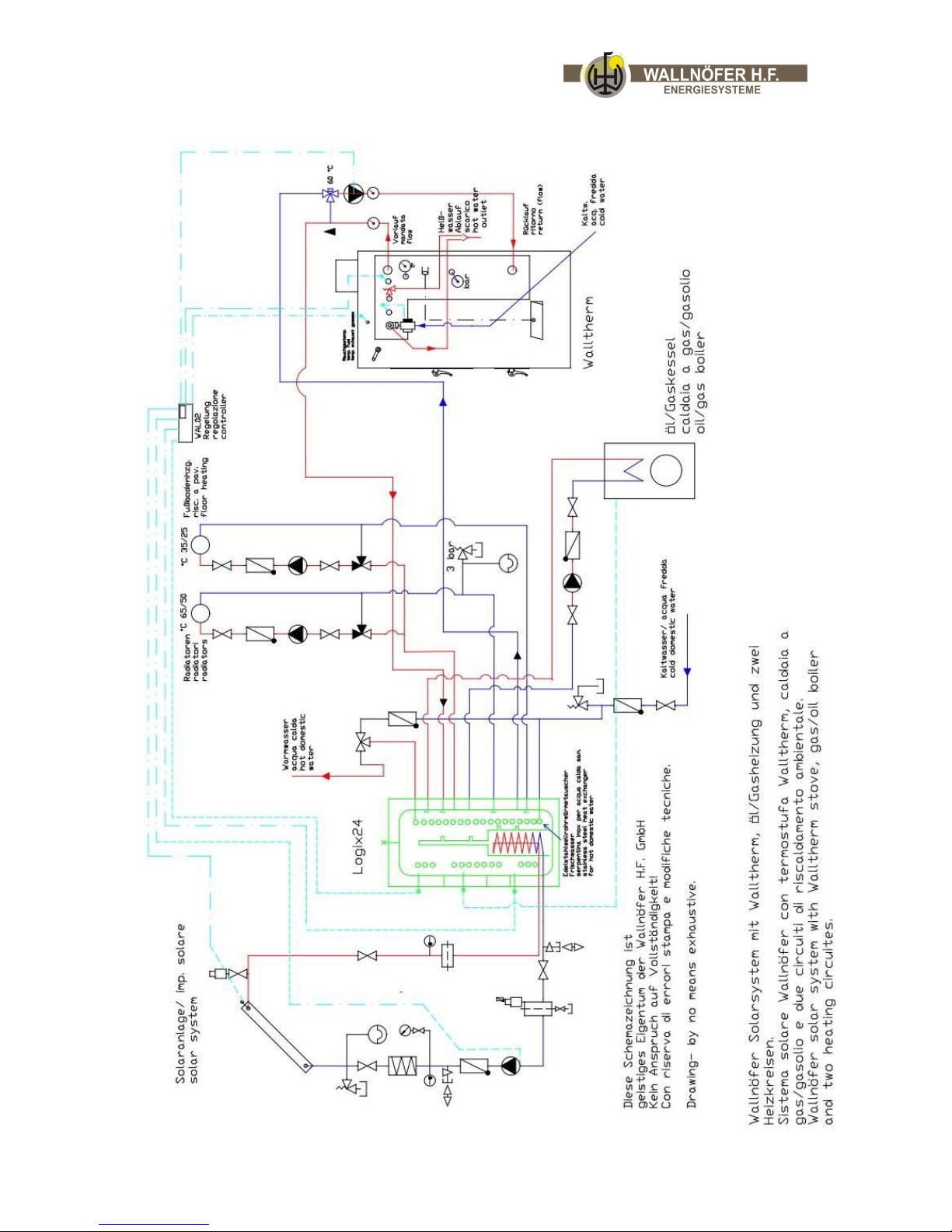
11. Concept of waterpipes
Page 43

progress & innovation 43/46
Indications for the connection to the pipe
An emptying tap has to be installed in lowest area of the water circulation.
The thermostat for pump’s beginning has to be set when it is in cold state.
The stove’s heat exchanger must not be the highest part/point of the system! If
necessary, move the pipe further up and install a ventilator.
The system’s pressure has to be controlled by a manometer.
The temperature of the heating water has to be checked through a thermometer.
Switching and regulation
a) Use of a regular thermostat, which is installed in the boiler 8a (simplest solution):
If the temperature of 60 – 70°C which is set at the thermostat 8a is achieved, the
circulation pump (water removal pump) starts and works in the area of 5 – 7° C
(switches on/off). If the stove cools down, the temperature of the boiler is lower than, for
instance, 55° C, the pump is switched off.
b) Alternative: Temperature differential regulation for example the new
regulation WAL02 (see chapter: 6.b.1. Electricity connection) with a sensor in the
stove’s boiler and a second sensor at the consumer (store/boiler, pipe): When the set
starting temperature is achieved (at least 50° C) the circulation pump starts working, if
the difference of temperature (set by the regulation) between the stove’s heating water
and the consumer (store/boiler, radiator) exists, e.g. 8° C more at the stove than at the
consumer. If the temperature is quite identical, the regulation switches off the pump.
N.B. When using this sensor, there are no more electrical and electronic functions and
connecting at the stove.
Back flow increase (pump group)
To avoid that the stove cools down due to its heating exchanger and too low water return
temperatures (less than 60°C) and to avoid the development of condensation, which
possibly happens with cold consumers and when the stove is started, we use a
thermostatically controlled 4-way valve set (7). This valve makes the heating water
partly re-circulate until the return temperature achieves more than 60° C. This group
Should be installed in the heating room directly at the storage tank.
Page 44
progress & innovation Vers. 12.1 44/46
12 Safety functions
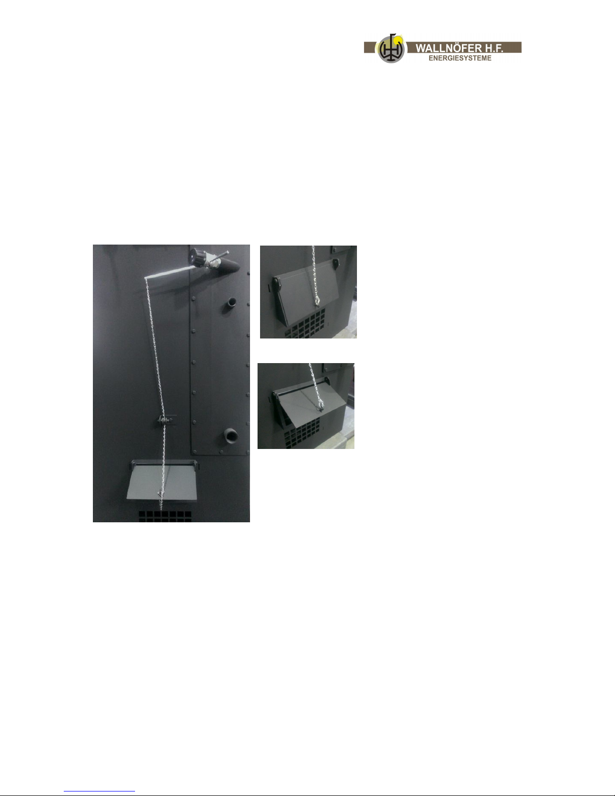
Thermostat at the air inlet with thermostatically controlled flap (6a)
A safety thermostat for control of combustion air intake 6b with connection bar and chain
is connected with a thermostatically controlled flap for combustion air 6a. If the
temperature of the boiler is higher than 80-95° C or if there are any malfunctions
concerning the heat extraction as, for instance, malfunctions of the pump, the mechanic
safety thermostat reduces the air supply to the combustion chambers through the air
inlet 6a. So the combustion temperature and the hot water temperature are decreasing.
Please see separate manual for correct adjustment of this safety function!
Regulator on 35°C= flap closed
Regulator on 80°-95°C = flap opened
You can shorten the chain after setting up the thermostat correctly!
Page 45
progress & innovation Vers. 12.1 45/46
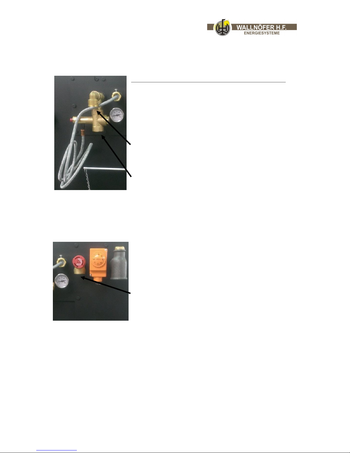
Thermal sfety drain
Thermal safety drain in case of overheating (8b, 8c, 8e):
As further safety precaution the oven has a thermal safety
frain consisting of a safety valve 8b, a heat exchanger 8c,
and a valve for thermal drain. In any case of overtemperature the valve 8e opens and makes the hot water
flow towards the drain. If this valve is defective, there is a
additional safety valve 8b which expels the hot water from
the boiler towards the drain.
Connection to the drain
Entrance for cold water
Please see separate manual for correct adjustment of this safety function!
Overpressure valve
The overpressure valve openes at 3bar.
Conncetion to the drain
Page 46
progress & innovation Vers. 12.1 46/46
13 Technical features/data
heating capacity: 14,9 KW/12.815 kcal
room heating capacity: 4,2 KW
water heating capacity: 10,7 KW
exhaust stream: 0,0107 kg/s
average exhaust temperature: 120-150° C
operating pressure: 2,5 bar max. 3 bar
controlling pressure: 5 bar
flue draught: 14 Pa/min. 12 Pa/1,2 mm Ws
weight: ca. 300 kg
water contents: 25 l
capacity (upper combustion chamber): ca. 55 l
Accepted, examined norms: EN 303-5, EN13240
Standard attachments:
back flow increase group (pump group) for installation in the heating cellar
set of stove instruments, consisting of poker and brush
ash shovel
cleaning brushes for the heating exchanger
Thank you very much
and
a South Tyrolean “Herzliches Vergelt’s Gott”
Thank you very much for having chosen the Walltherm stove and please enjoy this
innovative natural down-draught woodgasification stove.
The Team
Wallnöfer H.F. GmbH Energiesysteme
39026 Prad am Stj. (BZ) Gewerbezone 110
Tel. 0039 0473 616361 Fax 0039 0473 617141
Email: [email protected]
www.wallnöfer.com, www.wallnoefer.it, www.walltherm.com
 Loading...