

Wallgate WDC200 Product Manual
Product Manual
WDC200 Electronic Control
For Basins/Baths, Showers and WCs

2
Product Manual WDC200 Electronic Control
Revision 18
AS 1172
Certificate No
23167
RCM Mark
Australia

3
Product Manual WDC200 Electronic Control
Revision 18
Table of Contents
1. Disclaimer & Copyright Notice ............................................................................................... 4
2. Conventions ........................................................................................................................... 5
2.1. Warning ............................................................................................................................... 5
2.2. Note .................................................................................................................................... 5
2.3. Numbered procedures ....................................................................................................... 5
2.4. Bullet lists ............................................................................................................................ 5
2.5. Tick Bullet lists .................................................................................................................... 5
2.6. Menu items ......................................................................................................................... 5
3. Glossary .................................................................................................................................. 6
4. Product summary ................................................................................................................... 8
5. Installation and Commissioning ............................................................................................. 9
5.1. Package Contents ............................................................................................................... 9
5.2. Site Preparation .................................................................................................................. 9
5.2.1. Advice on attaching the unit ............................................................................................ 9
5.2.2. Electrical connections ...................................................................................................... 9
5.3 Attach the Controller Unit ................................................................................................ 10
5.4. Connect the Input and Output Cables .............................................................................. 11
5.5. Connect the 3-pin output connector ................................................................................ 13
5.6. Connect the 3.5mm input connector ............................................................................... 13
5.7. Connect the Electrical Supply ........................................................................................... 13
5.8. Commission the Unit ........................................................................................................ 14
5.9. Purge Cycle function ......................................................................................................... 14
5.10. Lockout function ............................................................................................................. 15
5.11. Piezo touch button and infrared sensor controls ........................................................... 16
5.12. System Test function ....................................................................................................... 17
5.13. Product Time Slots .......................................................................................................... 18
5.14. Hygiene Purge ................................................................................................................. 18
5.15. Data Logging .................................................................................................................... 18
5.16. Auto-Run ......................................................................................................................... 19
5.17. Technical Specifications .................................................................................................. 19
6. User and Maintenance Instructions ..................................................................................... 20
6.1. Operation .......................................................................................................................... 20
6.2. Maintenance ..................................................................................................................... 22
7. WDC200 Menu Settings ....................................................................................................... 22
8. Related Documentation ....................................................................................................... 30
9. Model Variations .................................................................................................................. 31

4
Product Manual WDC200 Electronic Control
Revision 18
9.1. WDC200-1 ......................................................................................................................... 31
9.2. WDC200-2 ......................................................................................................................... 31
9.3. WDC200-3 ......................................................................................................................... 32
1. Disclaimer & Copyright Notice
Every effort has been made to supply information within this manual which is correct.
Wallgate Limited will not be liable for any damage or loss that arises if the person
installing, operating or maintaining the unit has not read or not complied with the
manual
In any event, and without prejudice to any warranties in Wallgate Limited’s terms and
conditions of sale, Wallgate Limited’s liability for all damages and losses (including
negligence) shall not in any circumstances exceed the amount paid by the customer
for the unit.
Wallgate reserves the right to alter, update or improve its product specification at any
time without prior notice. This manual is specific to the product that it has been
supplied with at the date of supply.
Without prejudice to any warranties in Wallgate Limited’s terms and conditions of
sale, any warranty will be invalidated if the equipment is installed or serviced by
unqualified personnel.
No part of this publication and the information contained may be reproduced,
transmitted, stored in a retrieval system, used or disclosed wholly or partly without
prior written permission from Wallgate Limited.
For full warranty details please see Wallgate Limited Terms and Conditions.
Please ensure this manual is passed to the end user. The manual forms an integral
part of the product and should be kept for its working life. Additional copies of this
and other supporting documents are available by contacting Wallgate Limited or by
visiting www.wallgate.com

5
Product Manual WDC200 Electronic Control
Revision 18
2. Conventions
Certain conventions are used in this manual to make it easier to read and
understand. They are given in the sections below.
2.1. Warning
A warning with red text on a white background is used to give information about
hazards that can cause injury or death. Read and understand the warnings before
you install and commission the WDC200. Failure to heed these warnings can have
serious consequences.
WARNING! This is a warning!
2.2. Note
A note with amber text on a white background is used to draw your attention to
important and useful information.
NOTE: This is a note.
2.3. Numbered procedures
Steps in procedures are numbered, starting from 1.
1. This is step 1.
2. This is step 2 etc.
2.4 Bullet lists
2.4. Bullet lists
• A bullet list is used to give information that is not sequential.
2.5. Tick Bullet lists
✓ A tick bullet list is used to imply a checklist of components or actions (not
sequential).
2.6. Menu items
Menu items, submenu items and settings, where available, are given in bold.

6
Product Manual WDC200 Electronic Control
Revision 18
3. Glossary
The glossary lists all words, abbreviations and technical terminology used in this
manual, along with a short description of these terms.
Table 1. Glossary
Term
Description
Auto-run
The outputs to the water valves for basin, shower and
WC can be set to automatically operate at a set time
every day. The water valve will operate for the cycle set
run time as per a user activation. The Auto-run feature
can be used for maintaining hygiene standards similar to
the Hygiene Purge function detailed below, note that
only the Auto-run or Hygiene Purge would be utilized
and not both together.
Building Management
System
BMS
A Building Management System is a computer-based
control system installed in buildings that controls and
monitors the building’s mechanical and electrical
equipment such as ventilation, lighting, power systems,
fire systems, and security systems.
WDCMS
The WDCMS Wallgate system is use for standalone
networking of the WDC control units to a dedicated PC
or laptop computer. You can manage the WDC units
through the network. You can also adjust time cycle
settings, lockout settings, remote water isolation on
individual units or groups, RTC settings, etc. You can
also view the unit status in real time and log data.
Data Logging
Activations of the Hygiene Purge function detailed below
are logged in memory and then using additional software
the logs can be downloaded from the WDC200 and
imported into a spreadsheet report.
Dual Flush
This option is used when both full and half flush options
must be provided, using either one or two inputs.
Exclusivity
This feature prevents more than one water outlet from
being operated at a time.
Full Flush
This feature uses a 6 litre or 4.5 litre flush.
Reduced & Half Flush
The reduced flush is ⅔ of a full flush and the half flush ½
of a full flush.
Hygiene Purge
This feature operates services unused for a specified
number of days. This avoids water stagnation when the
services are unused for longer periods.
Latching
A latching switch is a switch that maintains its state after
being activated.

7
Product Manual WDC200 Electronic Control
Revision 18
Term
Description
Lockout
The term Lockout refers to regulating services by
restricting the number of usage cycles.
Momentary
A momentary switch returns to its normal OFF position
when released.
Piezo touch button
A piezoelectric touch button converts the force applied to
the face of the touch button into an electrical signal.
Power Rating
The power rating of a device is a guideline set by the
manufacturer as a maximum power to be used with that
device.
Purge Cycle
This feature is used to assist in removing air trapped in
the plumbing system.
Remote Lockouts
The term Remote Lockout refers to isolating water
services from a remote location.
RJ45 connection
The RJ-45 connectors are used to connect the WDC unit
to a PC or laptop.
RTC
Real Time Clock. This is a 24 hour 7 day clock used by
the WDC200 for program features such as Time Slots
and Hygiene Purge.
System Test
The System Test is a feature that allows you to operate
switches and touch buttons and make sure that these
operate the necessary outputs such as lights or valve
solenoids.
Time Slots
Usage of services such as basins, showers and WC
pans can be controlled using preset time slots. For
example, this feature can be used to prevent all the
showers in a facility being operated simultaneously
during peak periods, straining the capacity of the water
supply. The day is divided into 4 time slots, normally set
at 00:00 to 06:00, 06:00 to 12:00, 12:00 to 18:00 and
18:00 to 00.00.
Toggle type switch
A toggle switch is a class of electrical switches that are
actuated by a mechanical lever, handle, or rocking
mechanism.
Water Lockouts
Water Lockout means regulating water services by
restricting the number of usage cycles.

8
Product Manual WDC200 Electronic Control
Revision 18
4. Product summary
The WDC200 electronic control units are designed to operate the water outlets to a
wash basin* (x2) (Hot & Cold), a shower (x2) (premixed warm water) and the flush
for toilet water closet pan (x2) (WC). The WDC200 therefore has the capacity to
control two suites of products and can be located between two rooms.
*The WDC200 can be set to operate with a bath instead of a basin if required. This
would entail the installer or client adjusting water run times to 180 seconds for hot
and cold, or as preferred.
The WDCA200 model based upon the WDC200 is for 120v 60Hz electrical supply
operation using an external power adapter (UL/CSA approved) to connect to the
12VDC input socket on the WDCA200 control unit.
The control unit comprises of a microprocessor that is programmed with a software
program that has the following operational features:
• User friendly Software menu system with security controlled access.
• Independent control of multiple outlets.
• Fully programmable precise time control of water valve operation that is fully
adjustable in situ by the installer / customer.
• “LOCKOUT” function to prevent product misuse that is fully adjustable for the
number of user operations, operations period, lockout period, and the
“LOCKOUT” function can be ENABLED or DISABLED to suit the individual
requirements.
• Single or dual flush for WC control.
• Piezo touch button or infrared sensor capable inputs.
• Auxiliary inputs for remote operation of:
• Remote lockouts (Room 1 / Room 2).
• WC remote flush.
• WC reduced flush using a second touch button.
• Clear lockouts.
• Purge function.
• Not used
• Flow sensor for hygiene purge data logging.
• Multiple outlet control feature (COMMUNAL mode setting), so that one unit can
be used to operate up to eight water valves instead of default pre-sets for basins
and WC pans.
• Diagnostic test routine to assist with fault finding.
• Networking units to remotely control from a central PC desk position(s).
• Data logging of hygiene purges.

9
Product Manual WDC200 Electronic Control
Revision 18
5. Installation and Commissioning
5.1. Package Contents
Before you begin the installation, make sure that you have the following items:
✓ 1 WDC200 Electronic control unit
✓ 1 Product manual.
5.2. Site Preparation
5.2.1. Advice on attaching the unit
• Attached the unit to a vertical surface that is able to support the weight of the unit.
• Attach the unit in dry surroundings above pipes carrying water, away from any
possible plumbing leaks.
• Attach the electronic control unit where there is easy access. Attach the unit so
that the keypad and display on the unit are readily visible and accessible.
WARNING! Do not mount the unit upside down
The control box has four feet with holes for attaching the unit to the wall using four
round head screws, No 8 x 30mm (1.25 inch). For the location of the mounting feet,
refer to Figure 1 on page 10.
5.2.2. Electrical connections
• All cables must be connected to the unit using the sockets at the bottom of the
unit enclosure.
• The power cable must be connected to the unit through the cable gland.
• The control unit requires an electrical supply of 115-230V AC (Fuse 2 Amp) 50Hz
60 Watts.
• The mains supply cable from the unit must be terminated into a double pole fused
spur connection unit with a contact separation of at least 3mm. Use a 2 Amp fuse
in the connection unit.
• Place the connection unit near the controller unit.
• Position all electrical fittings such that water cannot drip on the electrical fittings if
a leak occurs, or a pipe bursts.
WARNING! The controller unit must be earthed using the earth lead in the
power cable.
10
Product Manual WDC200 Electronic Control
Revision 18
5.3 Attach the Controller Unit
To attach the control unit to the wall, do the following:
Mark the attachment points for the control unit on the wall. Make sure the cables
from the solenoid valves and Piezo touch buttons are of sufficient length to reach
the control unit. Refer to figure 1 for the location of the mounting feet.
Drill four mounting holes using a suitable drill bit.
Use suitable wall plugs if necessary.
Attach the unit to the wall using four round head screws.
NOTE: When mounting the unit, make sure the cable sockets at the bottom of
the unit point downwards.
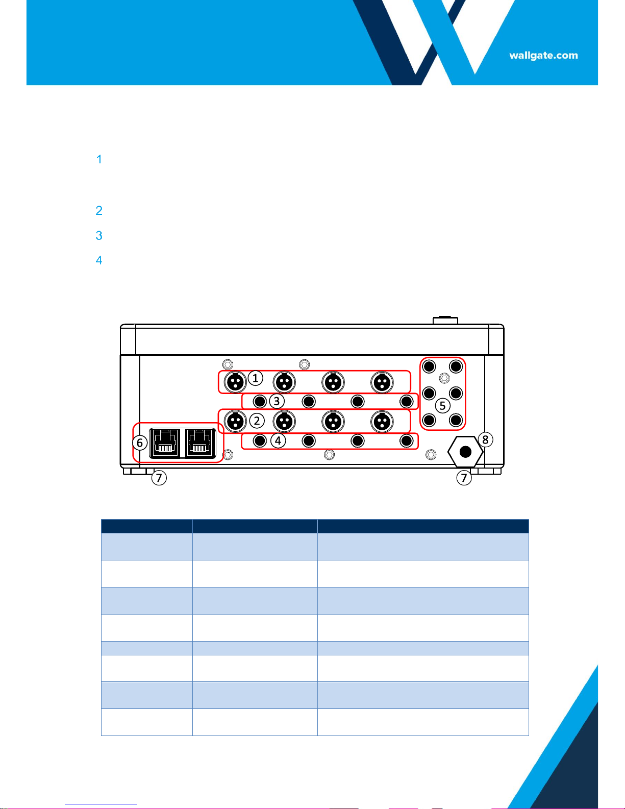
Figure 1.WDC200 Lower Panel
Table 2. Legend for Figure 1
Item number
Description
Function
1
Water Valve Cable
Sockets Room 1
Output to washbasin, WC and shower
valves in Room 1
2
Water Valve Cable
Sockets Room 2
Output to washbasin, WC and shower
valves in Room 2
3
Input Device Sockets
Room 1
Input from Piezo touch button or
infrared sensors Room 1
4
Input Device sockets
Room 2
Input from Piezo touch button or
infrared sensors Room 2
5
Auxiliary Inputs
Inputs for optional remote controls
6
Network Link Sockets
Input and output sockets for Ethernet
connection
7
Mounting feet
Use the feet to mount the control unit
to the wall
8
Power cable
Electrical power supply cable 1 metre
in length
 Loading...