

Wallenstein PTO62, PTO72 Installation Instructions Manual
EMB Manufacturing Inc.
4144 Boomer Line · St. Clements, Ontario · N0B 2M0 · Canada
www.wallensteinequipment.com
PTO62 & PTO72
HYDRAULIC PUMP KIT
Accessory Installation
Instructions
PTO62 PTO Hydraulic Pump Kit - 7GPM - 9.4 Litres (2.5 gal) uid tank - ts GX620
PTO72 PTO Hydraulic Pump Kit - 7GPM - 12.3 Litres (3.25 gal) uid tank - ts GX720, GX920, GX920XT
Do not attempt to start or operate the equipment without thoroughly reviewing this
manual for safe and proper operation.
Keep this manual with the
machine at all times
PRINTED IN CANADA
Rev 240517
Z97824 PTO62.PTO72 Backhoe Hydraulic Pump Kit.230517

SAFETY ALERT SYMBOL
This Safety Alert symbol means
ATTENTION! BECOME ALERT!
YOUR SAFETY IS INVOLVED!
Why is SAFETY important to you?
3 Big Reasons
SIGNAL WORDS:
Note: The use of the signal words DANGER,
WARNING, CAUTION and NOTICE with the
safety messages. The appropriate signal
word for each message has been selected
using the following guide-lines:
The Safety Alert symbol identies
important safety messages on the
Surge Master Wood splitter and in the
manual. When you see this symbol,
be alert to the possibility of personal
injury or death. Follow the instructions
in the safety message.
Accidents Disable and Kill
Accidents Cost
Accidents Can Be Avoided
DANGER - Indicates an imminently hazardous situation
that, if not avoided, will result in death or
serious injury. This signal word is to be limited
to the most extreme situations typically for
machine components which, for functional
purposes, cannot be guarded.
WARNING - Indicates a potentially hazardous situation
that, if not avoided, could result in death or
serious injury, and includes hazards that are
exposed when guards are removed. It may
also be used to alert against unsafe practices.
If you have any questions not answered in this manual or require additional copies or the manual is damaged,
please contact your dealer or EMB Mfg, 4144 Boomer Line, St. Clements, ON, N0B 2M0. Phone (519)
699-9283 or Fax (519) 699-4146.
Page 2 of 12
CAUTION - Indicates a potentially hazardous situation
that, if not avoided, may result in minor or
moderate injury. It may also be used to alert
against unsafe practices.
NOTICE -
Indicates a situation that could result in
damage to the machine or other property.
Accessory Installation Instructions
PT062 & PT072 HYDRAULIC PUMP KIT
Always wear the appropriate safety gear when installing
this kit or working around the machine. This includes but is
not limited to:
• Hard hat for protection to the head.
• Safety glasses protection for the eyes.
• Gloves for hand protection.
• Safety shoes with slip resistant soles and steel toes.
Caution: this kit is constructed of heavy gauge steel, be sure to use caution moving and installing the kit, avoid
dropping or pinching body parts on corners and edges of the kit.
Wallenstein PTO Hydraulic Pump Kit is required when mounting a Wallenstein backhoe on a tractor which has no or limited
hydraulics and will provide a 7GPM ow sufcient to power the back hoe. The PTO62 is used when mounting a GX620
Wallenstein backhoe, and the PTO72 is used when mounting a GX720, GX920 or GX920XT Wallenstein backhoe.
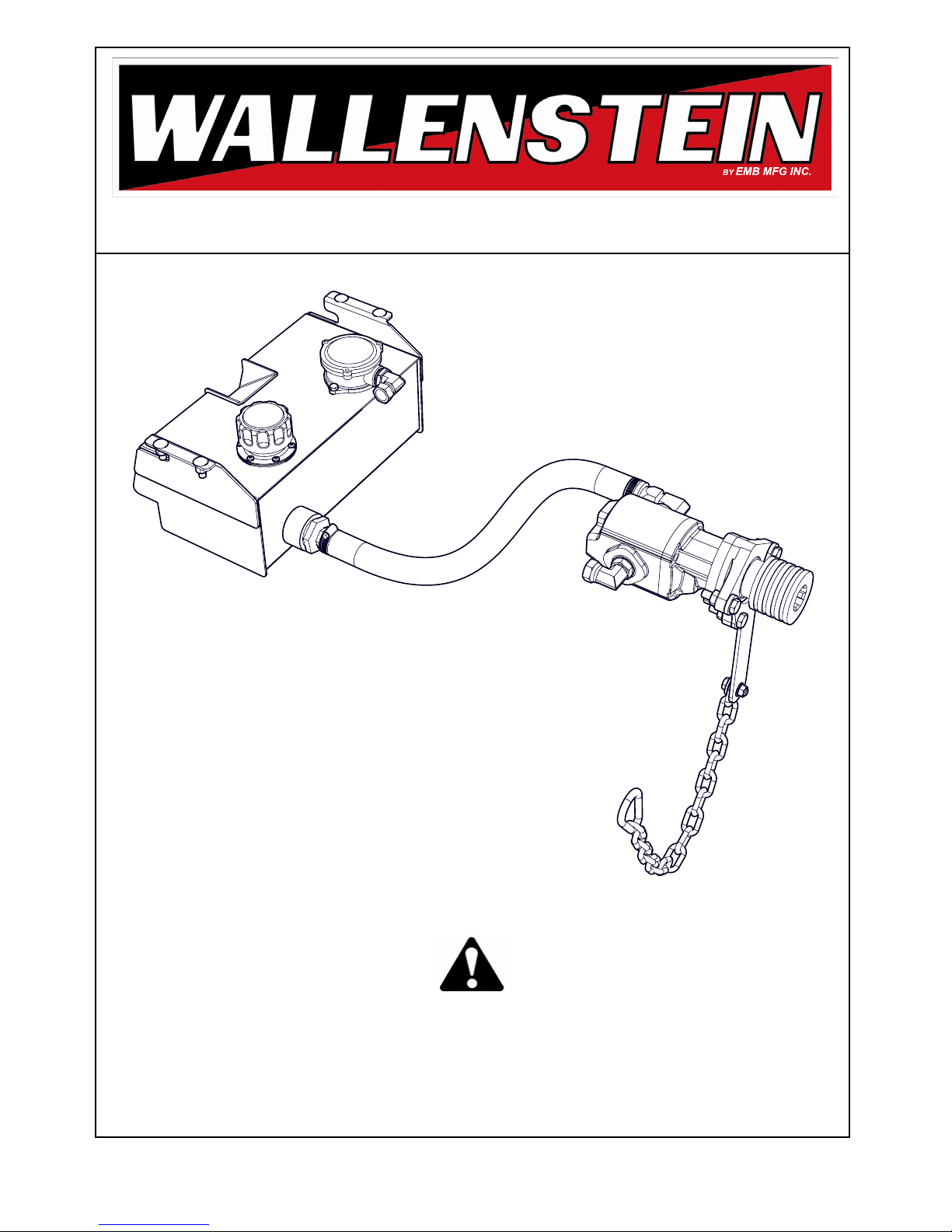
The PTO kits consists of a PTO mounted hydraulic pump, hydraulic tank with return hose and ttings and hardware in a
parts baggie.
There are 2 PTO Hydraulic Pump Kits:
PTO62 PTO Hydraulic Pump Kit - 7GPM - 9.4 Litres (2.5 gal) hydraulic tank - ts GX620
PTO72 PTO Hydraulic Pump Kit - 7GPM - 12.3 Litres (3.25 gal) hydraulic tank - ts GX720, GX920, GX920XT
Ensure you have the correct kit for your model backhoe.
Both PTO Hydraulic Pump Kits install in the same way for all models Installation and setup instructions apply to both kits
unless specied. Please read this manual thoroughly.
The PTO Hydraulic Pump Kit comes partially assembled. Illustrations show typical assembly. This assembly procedure is
one time only. Once assembled only regular maintenance and minor adjustments are required.
Tighten all hardware using the “Bolt Torque” chart at the back of this manual unless otherwise specied.
Tighten all hydrualic connections using the “Hydraulic Fitting Torgue” chart at the back of this manual unless otherwise
specied.
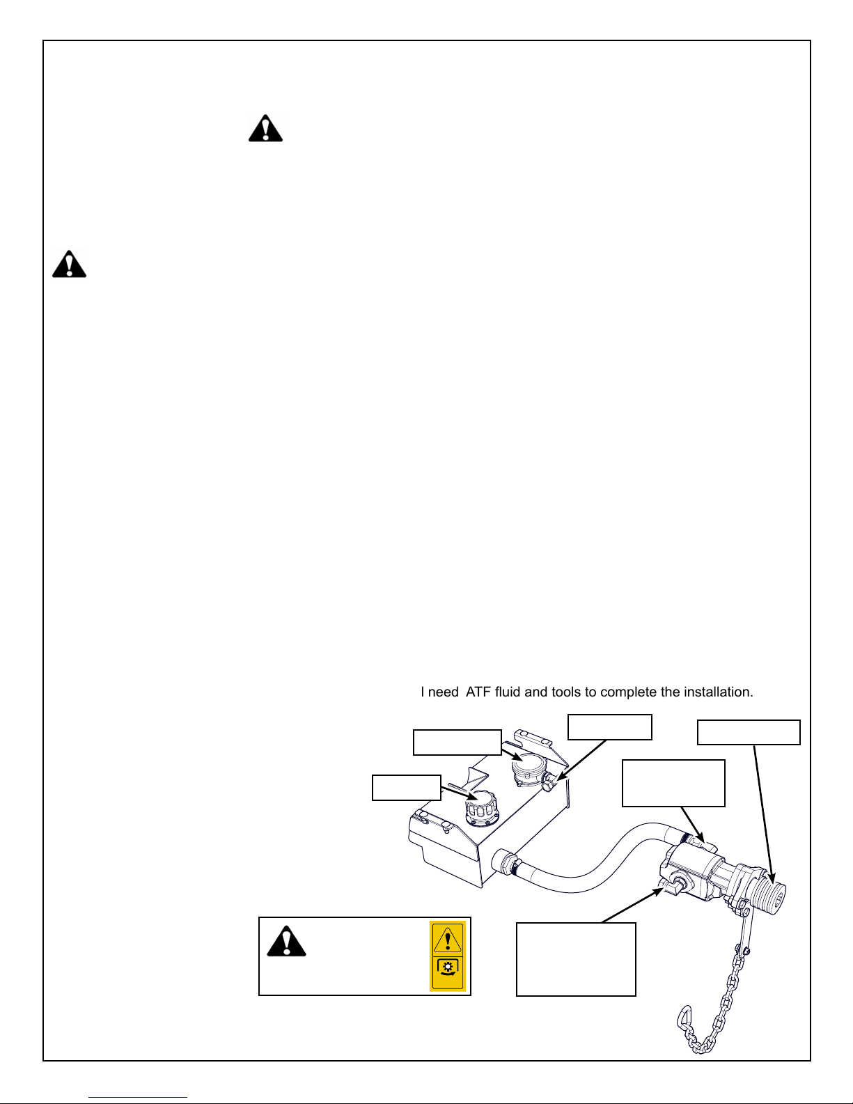
The #PTO62 / PTO72 kit comes partially assembled, you will need ATF uid and tools to complete the installation.
Before you start, you’ll need:
• Work bench, wrenches and sockets
• Dexron III ATF uid:
• PTO62: 9.4 Litres (2.5 gal)
• PTO72: 12.3 Litres (3.25 gal)
• Model specic instructions that came
with the backhoe mounting kit to
complete the hookup.
• Funnel and rags.
• Thread Sealant
Pump is rated to run at 540
RPM only
Filler Cap
Notice:
Operation Hazard:
Filter Cover
540 RPM
Z94246
input to backhoe
pressure line)
Return line
control (high
locking collar
Suction from
Tank
Page 3 of 12

Installation Instructions:
Ensure the Backhoe and the area around it is clean and free of debris, resting on dry level
ground, and detached from the tractor. Leave enought working space between the tractor and
backhoe.
Install the Reservoir
1. Before starting, clear the area of bystanders,
especially small children.
2. On the workbench, attach the 1/2” elbow con-
nector to the lter head. (pre-installed on PTO72)
3. Next attach the 3/4” barbed hose tting to the
tank.
4. Tighten connections as specied in the Hydrau-
lic Fitting Torque Chart.
5. Slip the gear clamps over the suction hose,
6. Attach one end of the suction hose to the tank
and to the other end to the input of the PTO
pump, and tighten gear clamps.
7. Prepare to install the reservoir tank by ensuring the backhoe frame is clean and clear
and the hydraulic hoses are out and won’t be
caught behind the tank.
8. Mount the oil reservoir to the backhoe frame:
• Move the tank into position.
• Install bolts thru rectangular holes in the
foot rest into the tank mounting holes.
• Adjust the tanks position as required
then tighten mounting bolts. (see torque
chart)
Page 4 of 12
Mounting
 Loading...