

Page 1
OPERATOR'S MANUAL
FX
FX
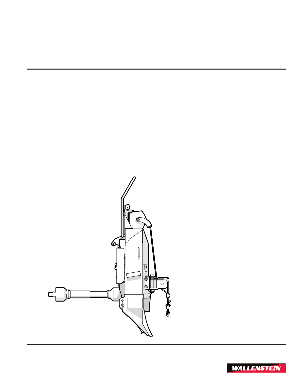
PTO-driven Log Skidding Winch
110/R,
66,
FX
FX
85/R
140/R
Z97090_EnRev Apr-2019
Page 2

Foreword
1. Foreword
1.1 Introduction
Congratulations on your choice of a Wallenstein
PTO-Driven Log Skidding Winch !
FX Series Winches are designed to pull those hard to
reach logs, even on steep hills or through swampland.
This manual covers the following models:
FX66, FX85, FX85R, FX110, FX110R, FX140, and
FX140R
FX66, FX85/R, FX110/R, FX140/R
PTO Skidding Winch
WARNING!
Do not attempt to start or operate the machine
without thoroughly reviewing this manual for
safe and proper operation.
Keep this manual with the machine at all times.
W034
NOTE:
Safe, efcient and trouble free operation of this
Wallenstein product requires that anyone using or
maintaining the machine reads and understands the
Safety, Operation, Maintenance information contained
within this Operator's Manual.
Units of measurement in Wallenstein Equipment
technical manuals are written as:
US Customary (SI metric).
Keep this manual handy for frequent reference and
to pass on to new operators or owners. Call your
Wallenstein dealer or distributor if you need assistance,
information or additional copies of the manuals.
Wallenstein Equipment Inc. • © 2019
FX85R, FX110R and FX140R models are
equipped with remote winch control.
www.wallensteinequipment.com
2
Page 3

FX66, FX85/R, FX110/R, FX140/R
PTO Skidding Winch
Foreword
Table of Contents
1. Foreword ................................................................2
1.1 Introduction ......................................................2
1.2 Delivery Inspection Report ..............................4
1.3 Serial Number Location ...................................5
1.4 Warranty ..........................................................6
1.5 Decal Information ............................................7
2. Safety ......................................................................8
2.1 Safety Alert Symbol .........................................8
2.2 Signal Words ...................................................8
2.3 Why is SAFETY important? .............................9
2.4 Safety Rules ....................................................9
2.5 Operating Safety ............................................10
2.6 Equipment Safety Guidelines ........................10
2.7 Safety Training ..............................................10
2.8 Preparation ....................................................11
2.9 Sign-Off Form ................................................12
2.10 Safety Sign Explanations ...............................13
2.11 Replace Damaged Safety Signs ....................17
2.12 How to Install Safety Signs ............................17
3. Familiarization......................................................18
3.1 To the New Operator .....................................18
3.2 Operator Orientation ......................................18
3.3 Training ..........................................................18
3.4 Job Site Familiarization .................................18
3.5 Equipment Condition .....................................19
3.6 Winch Components .......................................20
4. Attaching Winch to Tractor .................................21
4.1 Determine Proper PTO Shaft Length ............22
4.2 Shortening PTO Shaft ...................................23
4.3 Winches with Remote Control .......................23
5. Controls ................................................................24
5.1 Winch Clutch .................................................24
5.2 Winch Drum Lock ..........................................24
5.3 Forged Cable End .........................................25
5.4 Keyhole Sliders ..............................................25
5.5 Keyhole Slots .................................................25
5.6 Choker Chains ..............................................26
5.7 Lower Snatch Block .......................................26
5.8 Trailer Hitch ...................................................26
5.9 Safety Screen ................................................27
5.10 Remote Winch Control .................................27
6. Operating Instructions ........................................30
6.1 Pre-start Checklist .........................................30
6.2 Machine Break-In ..........................................31
6.3 Winch Safety .................................................31
6.4 Winching Logs ...............................................32
6.5 Skidding Logs ................................................33
7. Service and Maintenance ....................................35
7.1 Maintenance Safety .......................................35
7.2 Maintenance Schedule ..................................36
7.3 Grease Points ................................................36
7.4 Drive Chain Lubrication .................................37
7.5 Drive Chain Tension .....................................38
7.6 Clutch Adjustment .........................................38
7.7 Drum Brake Adjustment ................................39
7.8 Cable Install ...................................................40
7.9 Brake and Clutch Rope Routing ....................40
8. Storage .................................................................41
9. Transporting .........................................................41
10. Troubleshooting .................................................42
11. Specications.....................................................44
11.1 Machine Specications ..................................44
11.2 Bolt Torque ....................................................45
11.3 Hydraulic Fitting Torque ................................46
12. Alphabetical Index .............................................47
3
Page 4

Foreword
FX66, FX85/R, FX110/R, FX140/R
PTO Skidding Winch
1.2 Delivery Inspection Report
WALLENSTEIN
FX Series Skidding Winch
To activate warranty, register your product online at
http://www.wallensteinequipment.com
This form must be lled out by the dealer and signed by both the dealer and the customer at the time of delivery.
_________________________________________
Customer’s Name
Pre-delivery Inspection
_________________________________________
Contact Name
_________________________________________
Dealer Name
(_________)_______________________________
Phone Number
_________________________________________
Serial Number
__________ /__________ /__________
Delivery Date (dd/mm/yy)
I have thoroughly instructed the buyer on the equipment care, adjustments, safe operation and applicable
warranty policy and reviewed the manuals.
_________________________________________
Dealer’s Rep. Signature
Inspect for damage from shipping. Immediately
contact the shipping company if damage is found.
All FX Series
Check Condition of Cable
Drive Chain Tension Checked
PTO Shaft Telescopes, Shield Turns, and is
Greased
Fasteners Tight
Grease Zerks / Pivot Points Lubricated
Clutch Rope Moves Freely
Brake Rope Moves Freely
FX85R, FX110R, FX140R
Remote Control Functions Correctly
Clutch Hydraulic Cylinder Functions
Check Electrical Power Connections
Check Wiring Connections
Safety Checks
All Safety Decals Installed
Guards and Shields Installed and Secured
Retainer Installed Through Mounting Pins
Review Operating and Safety Instructions
__________ /__________ /__________
Delivery Date (dd/mm/yy)
The product manuals have been received by me and
I have been thoroughly instructed as to care, adjustments, safe operation and applicable warranty policy.
_________________________________________
Owner's Signature
__________ /__________ /__________
Delivery Date (dd/mm/yy)
4
Page 5
FX66, FX85/R, FX110/R, FX140/R
PTO Skidding Winch
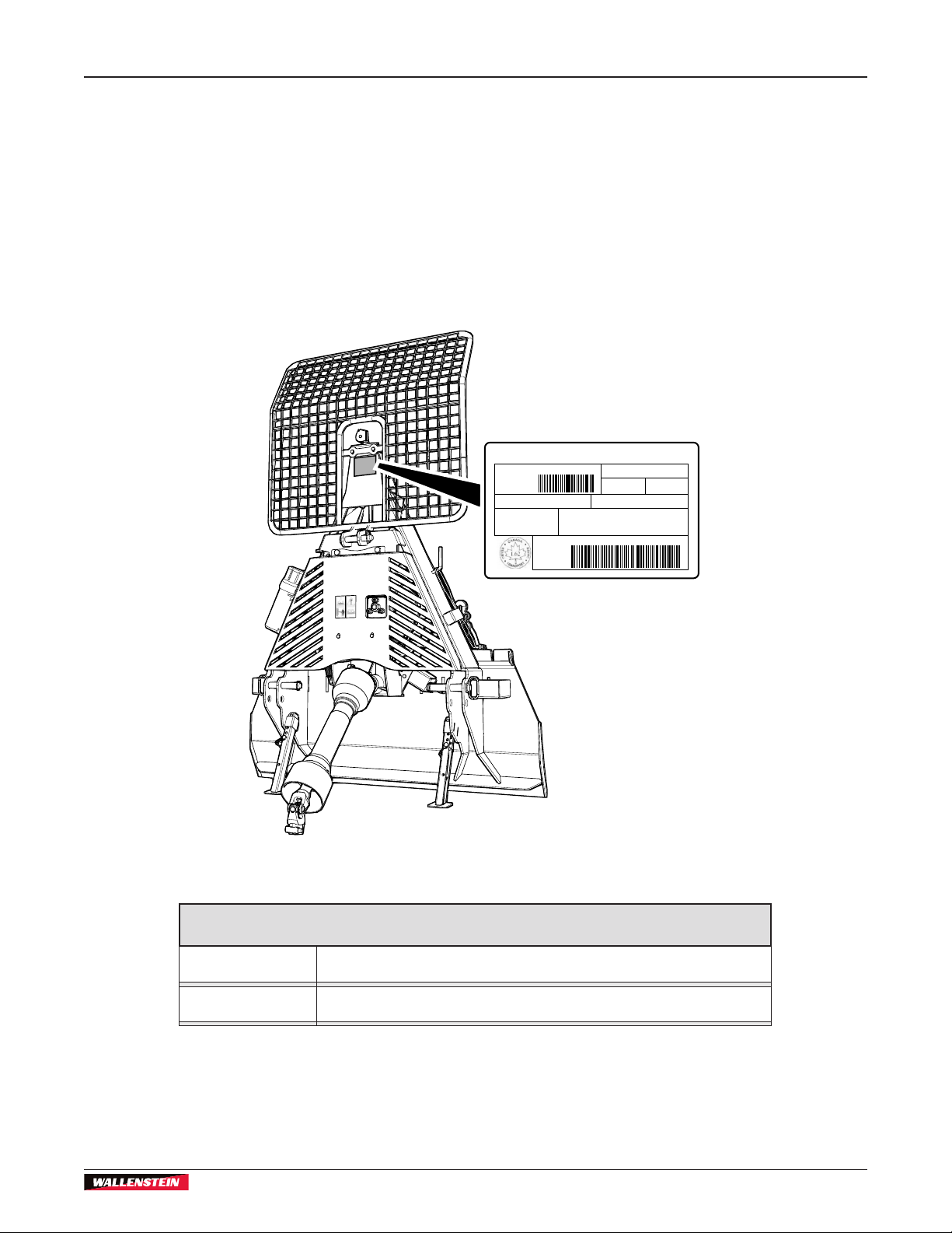
1.3 Serial Number Location
Always provide the model and serial number of your
Wallenstein product when ordering parts or requesting
service or other information. This information is found
on the serial number plate shown in the illustration
below.
Record product information in the spaces provided
for future reference.
Manufactured by:
Wallenstein Equipment Inc., 7201 Line 86, Wallestein ON N0B2S0, Canada
MODEL: ##########
DIMENSION- RIM/JANTE /ERIT : PNEU:
###
COLD INFL. PRESS/PRESS DE
CONFLA A FROID (PSI/LPC):
###
VIN/
NLV:
TYPE OF VEHICLE/TYPE DE VEHICLE:
TRA / REM
GAWR/PNBE (KG): GVWR/PNBV (KG):
###
THIS VEHICLE CONFORMS TO ALL APPLICABLE STANDARDS
PRESCRIBED UNDER THE CANADIAN MOTOR SAFTEY REGULATIONS
IN EFFECT ON THE DATE OF MANUFACTURE / CE VEHICLE EST
CONFORME A TOUTES LES NORMES QUI LUI SONT APPLICABLES EN
VERTU DU REGLEMENT SUR LA SECURITE DES VEHICLES
AUTOMOBILES DU CANADA EN VIGUEUR A LA DATE DE SA FABRICATION.
#########
###
Foreword
###
Model:
Serial Number:
00576
Fig. 1 – Serial Number Plate Location
Record Product Information Here
5
Page 6

Foreword
1.4 Warranty
Wallenstein products are warranted to be free of defects in materials and
from the date of purchase, when operated and maintained in accordance with the operating
and maintenance instructions supplied with the unit. Warranty is limited to the repair of the
product and/or replacement of parts.
FX66, FX85/R, FX110/R, FX140/R
PTO Skidding Winch
LIMITED WARRANTY
workmanship under normal use and service, for a period of
Five Years for Consumer Use
Two Years for Commercial/Rental Use
This warranty is extended only to the original purchaser and is not transferable.
Repairs must be done by an authorized dealer. Products will be returned to the dealer at the
customer’s expense. Include the original purchase receipt with any claim.
This warranty does not cover the following:
1) Normal maintenance or adjustments
2) Normal replacement of wearable and service parts
3) Consequential damage, indirect damage, or loss of profits
4) Damages resulting from:
• Misuse, negligence, accident, theft or fire
• Use of improper or insufficient fuel, fluids or lubricants
• Use of parts or aftermarket accessories other than genuine Wallenstein parts
• Modifications, alteration, tampering or improper repair performed by parties other
than an authorized dealer
• Any device or accessories installed by parties other than an authorized dealer
5) Engines. Engines are covered by the manufacturer of the engine for the warranty period
they specify. For the details of your engine warranty, see your engine owner’s manual.
Information about engine warranty and service is also available in the FAQ section at
www.wallensteinequipment.com
rev. Nov-2018
6
Page 7
FX66, FX85/R, FX110/R, FX140/R
PTO Skidding Winch
Foreword
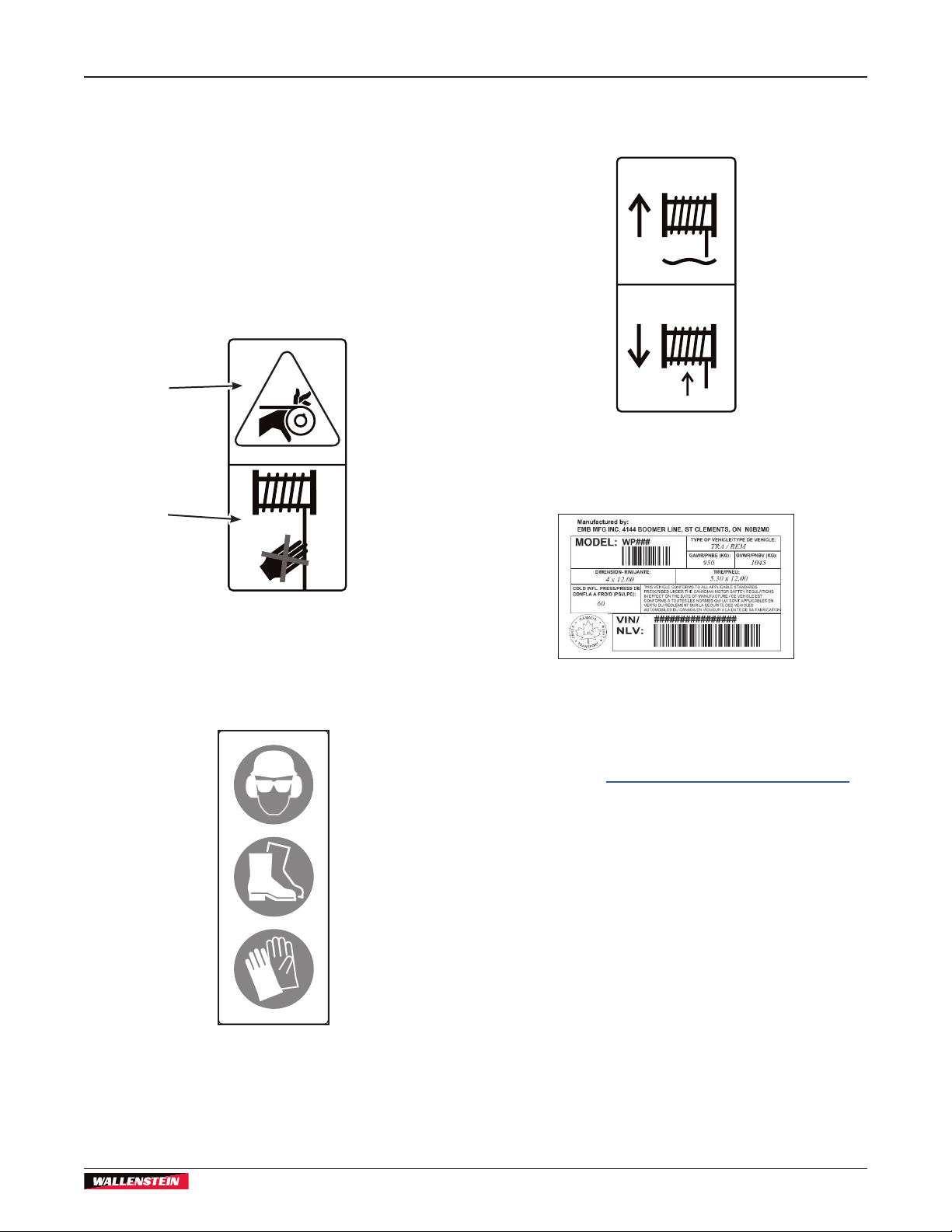
1.5 Decal Information
When getting familiar with the Wallenstein product,
notice that there are numerous decals located on the
machine. There are different types of decals for safety,
information, and product identication. The following
section explains what they are for and how to read
them.
Safety Decals are pictorial with a yellow background
and generally two panel. The top panel shows the
safety alert (the potential hazard) and the bottom panel
shows the message (how to avoid the hazard).
Potential
Hazard
How
Hazard is
Avoided
Informative Decals are generally pictorial with a white
background and can vary in the number of panels. This
type of decal explains the operation of a control.
Product Decals indicate machine model and serial
number, and other important information.
Safety Notice Decals are pictorial with a blue
background and generally rectangular with single or
multiple symbols. This decal informs what Personal
Protective Equipment is required for safe operation.
See the section on safety signs for safety decal
denitions. For a complete illustration of decals and
decal locations, download the parts manual for your
model product at www.wallensteinequipment.com.
7
Page 8

2. Safety
2.1 Safety Alert Symbol
This Symbol means:
ATTENTION! BE ALERT !
Safety
YOUR SAFETY IS INVOLVED !
The Safety Alert Symbol identies important safety
messages on the Wallenstein product and in the
manual.
When you see this symbol, be alert to the
possibility of personal injury or death! Follow the
instructions in the safety message.
Safety
FX66, FX85/R, FX110/R, FX140/R
PTO Skidding Winch
2.2 Signal Words
The signal words DANGER, WARNING and CAUTION
determine the seriousness level of the warning
messages in this manual. The appropriate signal word
for each message in this manual has been selected
using the following guidelines:
DANGER –
Indicates an imminently hazardous situation that,
if not avoided, will result in death or serious injury.
This signal word is to be limited to the most extreme
situations typically for machine components which, for
functional purposes, cannot be guarded.
WARNING –
Indicates a potentially hazardous situation that, if not
avoided, could result in death or serious injury, and
includes hazards that are exposed when guards are
removed. It may also be used to alert against unsafe
practices.
CAUTION –
Indicates a potentially hazardous situation that, if not
avoided, may result in minor or moderate injury. It may
also be used to alert against unsafe practices.
IMPORTANT – To avoid confusing equipment
protection with personal safety messages, a signal
word IMPORTANT indicates a situation that if not
avoided, could result in damage to the machine.
NOTE:
(plus text) – indicates an additional
explanation for an element of information.
8
Page 9
FX66, FX85/R, FX110/R, FX140/R
PTO Skidding Winch
Safety
2.3 Why is SAFETY important?
Three Big Reasons:
• Accidents Disable and Kill
• Accidents Cost
• Accidents Can Be Avoided
YOU are responsible for the SAFE operation and
maintenance of your Wallenstein Log Skidding Winch.
YOU must make sure that anyone who is going to use,
maintain or work around the winch is familiar with the
operating and maintenance procedures and related
SAFETY information contained in this manual.
Remember, YOU are the key to safety. Good safety
practices not only protect you but also the people
around you. Make these practices a working part of
your safety program. Be certain that EVERYONE
using this equipment is familiar with the recommended
operating and maintenance procedures and follows
all the safety precautions. Most accidents can be
prevented.
Do not risk injury or death by ignoring good safety
practices.
2.4 Safety Rules
• DO give operating instructions to
operators or employees before
allowing them to operate the
machine.
• DO always wear appropriate Personal Protective
Equipment (PPE). This equipment includes but is
not limited to the following:
- A hard hat
- Heavy gloves
- Hearing protection
- Protective shoes with slip resistant soles
- Protective glasses, goggles or face shield
• DO set the machine in a Safe Condition before
performing any service, maintenance work, storage
preparation, or hooking up. Safe Condition
involves performing the following:
SAFE CONDITION
1. Disengage the PTO.
2. Set the parking brake.
3. Turn tractor engine off. Remove the ignition key.
Block the tractor wheels.
4. Make sure all components have stopped moving.
5. Check winch cable is not under tension.
• DO have a rst-aid kit available
for use should the need arise and
know how to use it.
• DO read and learn all safety signs located on the
machine before using, maintaining, adjusting or
cleaning the winch.
• DO inspect and secure all guards before starting.
• DO have a re extinguisher available for
use should the need arise and know how
to use it.
• DO NOT expect a person who has not read and
understood all use and safety instructions to
operate the machine. An untrained operator is not
qualied and exposes himself and bystanders to
possible serious injury or death. It is the owners
responsibility to the operator to make sure
familiarity and understanding of the machine.
• DO NOT modify the equipment in any way.
Unauthorized modication may impair the function
and/or safety and could affect the life of the
equipment.
• DO NOT allow riders during transport.
• DO NOT risk injury or death by ignoring good
safety practices.
Safety
9
Page 10

Safety
FX66, FX85/R, FX110/R, FX140/R
PTO Skidding Winch
2.5 Operating Safety
Safety
• Understand the meaning of the safety signs on the
machine. Keep them clean. Replace them if they
become damaged.
• Never operate this winch with guards or shields
removed. The manufacturer has designed this
skidding winch to be used with all its safety
equipment properly attached, to minimize the
chance of accidents.
• Read and understand the operator's manual before
starting. Review safety instructions annually.
• Do not allow anyone within 20 ft (6 m) of machine
or logs during operation.
• Stand at least 10 ft (3 m) to the side to activate the
winch.
• Do not touch or stand directly in line with cable
during operation.
• Check cable condition before using winch. Cable
can break if it is kinked, corroded, knotted, or has
broken strands. Replace if damaged.
• Never consume alcohol or take drugs that could
hinder alertness or coordination while operating
this equipment. Consult a doctor about operating
this machine if taking prescription medications.
• Do not allow riders on this machine at any time.
There is no safe place for any riders.
• Keep rear tractor wheels on level ground and lower
winch blade when winching to provide stability.
• Do not exceed winching angle of more than 25° off
center.
• Always winch up a slope. It is not safe to winch
down slope. Logs could roll unpredictably. Do not
winch across a slope.
• Do not operate on hillsides or when working area is
cluttered, wet, muddy or icy to prevent slipping and
tripping.
• Keep all components of PTO systems shielded and
guarded.
• Regularly test driveline guards by spinning or
rotating them to make sure they have not become
stuck to the shaft.
• Disengage the PTO and shut off the tractor before
dismounting to clean, repair, service, or adjust
machinery.
• Walk around tractors and machinery rather than
stepping over a rotating shaft.
• Do not exceed a safe travel speed when
transporting.
2.6 Equipment Safety Guidelines
• Keep all shields in place. If shield removal
becomes necessary for repairs, replace the shield
prior to use.
• Replace any safety sign or instruction sign that is
not readable or is missing. Location of such safety
signs are indicated in this manual on page 13.
• Do not modify the equipment in any way.
Unauthorized modication may result in serious
injury or death and may impair the function and life
of the equipment.
• Never exceed the limits of the machine. If its ability
to do a job is in question, or to do so safely –
STOP !
2.7 Safety Training
• Safety is a primary concern in the design and
manufacture of our products. Unfortunately, our
efforts to provide safe equipment can be wiped
out by a single careless act of an operator or
bystander.
• The best safety feature is an
informed, careful operator—we
ask you to be that kind of an
operator. It is the operator's
responsibility to read, understand
and follow ALL safety and
operation instructions in the
manual. Review Safety Sign
Explanations on page 13.
• Working with unfamiliar equipment can lead
to careless injuries. Read this manual before
assembly or using the machine to acquaint
yourself with it. If this machine is used by any
person other than yourself, or is loaned or rented,
it is the machine owner's responsibility to make
certain that prior to using, the operator:
- reads and understands the owner's manual
- is instructed in safe and proper use of the
equipment
- understands and knows how to perform the
Safe Condition procedure
10
Page 11

FX66, FX85/R, FX110/R, FX140/R
PTO Skidding Winch
Safety
• Train all new personnel and review instructions
frequently with existing workers. Be certain only
a properly trained and physically able person
will use the machinery. Anyone not familiar with
operation and safety instructions is not qualied to
use the machine. An untrained operator exposes
himself and bystanders to possible serious injury
or death. If the elderly are assisting with the work,
their physical limitations need to be recognized and
accommodated.
• Know your controls and how to stop the machine
quickly in an emergency. Read this manual
thoroughly.
2.8 Preparation
• Never use the machine until the operators have
been adequately trained in the safe operation
of the machine and have read and completely
understand:
- safety, operation and feature sections of this
manual
- each of the safety messages found on the
safety signs on the machine.
- engine operator's manual
• Perform the Pre-start Checklist procedure before
starting work (see Pre-Operation Checklist on page
30).
• Replace any hydraulic hose immediately that
shows signs of swelling, wear, leaks or damage
before it bursts.
• Do not bend or strike high-pressure lines, tubes
or hoses, or reinstall them in a bent or damaged
condition.
• Check to make sure hydraulic hoses are not worn
or damaged, and are routed to avoid chang.
• Never adjust a pressure relief valve or other
pressure-limiting device to a higher pressure than
specied.
Safety
• PPE is recommended during assembly, installation,
operation, adjustment, maintaining, repairing,
removal, cleaning, or moving the trailer. Do not
allow long hair, loose tting clothing or jewelry
around equipment.
• Prolonged exposure to loud noise
may cause permanent hearing
loss! Power equipment with or
without equipment attached can
often be noisy enough to cause
permanent, partial hearing loss.
We recommend that you wear
hearing protection on a full-time
basis if the noise in the Operator's
position exceeds 80 dB. Noise
over 85 dB on a long-term basis
can cause severe hearing loss.
Noise over 90 dB adjacent to
the Operator over a long-term
basis may cause permanent, total
hearing loss.
• Be aware of overhead hazards: branches, cables,
electrical wires.
• Use only in daylight or good articial light.
• Make sure that all safety shielding and safety signs
are properly installed and in good condition.
11
Page 12

Safety
FX66, FX85/R, FX110/R, FX140/R
PTO Skidding Winch
2.9 Sign-Off Form
Wallenstein Equipment Inc. follows the general safety
standards specied by the International Organization
for Standardization (ISO), and additionally those
referenced by the American Society of Agricultural and
Biological Engineers (ASABE).
Safety
Anyone who will be using and/or maintaining the winch
must read and clearly understand ALL Safety, Usage
and Maintenance information presented in this manual.
Do not use or allow anyone else to use this winch until
such information has been reviewed. Annually review
this information before the season start-up.
Make these periodic reviews of SAFETY and
OPERATION a standard practice for all of your
equipment. We feel that an untrained operator is
unqualied to use this machine.
A sign-off form provided below can be used to record
personnel working with the equipment have read and
understand the operator's manual and are trained in
the equipment operation.
Sign-off Form
Date Owner Employee
12
Page 13
FX66, FX85/R, FX110/R, FX140/R
PTO Skidding Winch
Safety
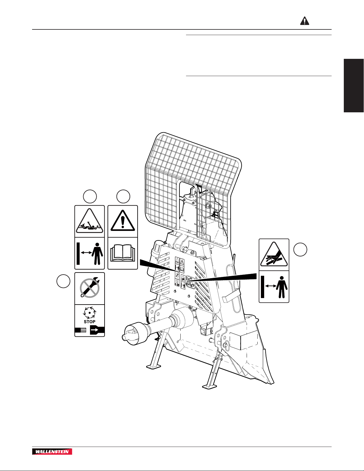
2.10 Safety Sign Explanations
Safety signs on the equipment are explained in the
pages that follow.
Working safely requires familiarizing yourself with the
various safety signs, the type of warning and the area,
or particular function related to that area, that requires
your SAFETY AWARENESS.
Think SAFETY! Work SAFELY
12
IMPORTANT! If parts are replaced that have
safety signs on them, new signs must be applied.
Safety signs must always be replaced if they
become damaged, are removed, or become
illegible.
Safety signs are included in the product decal kit
available from your authorized dealer. Decals are not
available separately.
Safety
4
3
00578
Fig. 2 – FX-Series Safety Decal Placement
13
Page 14
Safety
FX66, FX85/R, FX110/R, FX140/R
PTO Skidding Winch
Safety
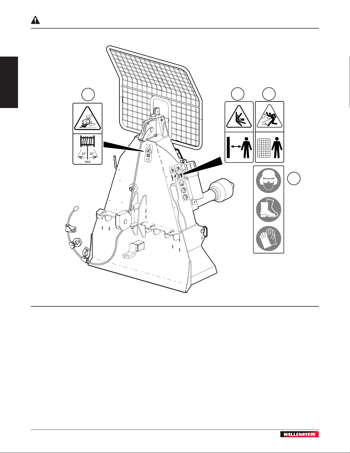
5
6 7
8
00577
Fig. 3 – Fx-Series Safety Decal Placement
14
Page 15
FX66, FX85/R, FX110/R, FX140/R
PTO Skidding Winch
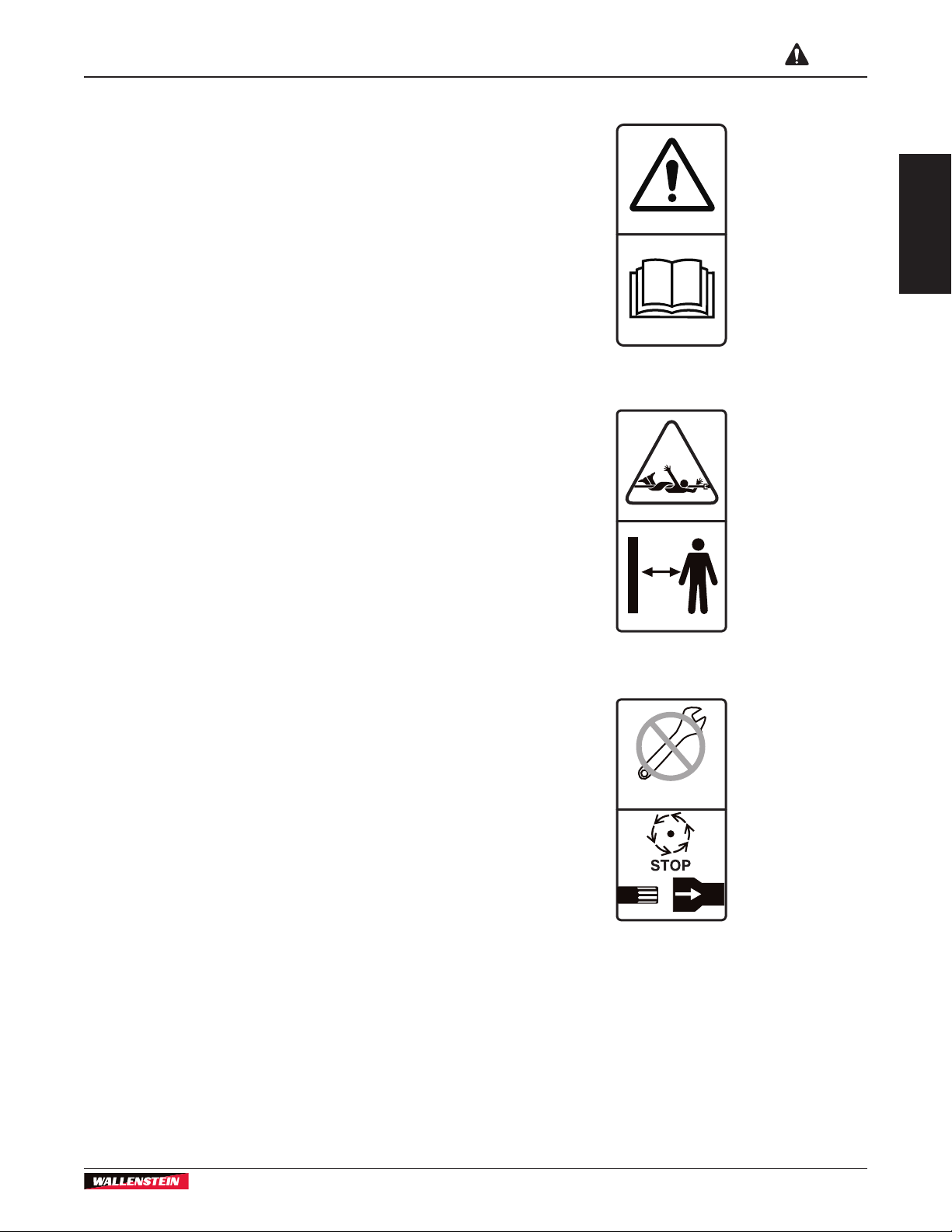
1. Caution!
Refer to the operator's manual. Read ALL operating
instructions in the manual and learn the meaning of
ALL safety signs on the machine.
The best safety feature is an informed operator.
2. Warning!
Risk of entanglement from rotating driveline.
Keep hands, loose clothing, and long hair away from
driveline while it is rotating.
Safety
Safety
3. Warning!
Risk of injury when servicing or repairing this machine.
Disconnect the driveline before working on this
machine.
15
Page 16

Safety
Safety
4. Warning!
Concealed hydraulic uid connection under pressure.
Use caution when removing panels or guards. Do not
check for leaks with your hand or ngers when the
system is pressurized. Serious injury can result.
(R-models only, equipped with remote control)
5. Warning!
Risk of tractor overturning.
Do not operate with the winch cable angle greater than
25° off center, in either direction.
FX66, FX85/R, FX110/R, FX140/R
PTO Skidding Winch
6. Warning!
Crushing hazard.
Do not stand in front of the winch when using it. Stand
to the side at a minimum 10 ft (3 m) away.
16
Page 17

FX66, FX85/R, FX110/R, FX140/R
PTO Skidding Winch
7. Warning!
Be aware of the risk of injury from ying objects. Stay
behind the protective screen when possible. Cable
could release from a log unexpectedly and snap back
fast enough to cause injury.
8. Warning!
Always wear appropriate Personal Protective
Equipment when using this machine. For example:
• A hard hat
• Heavy gloves
• Hearing protection
• Protective shoes with slip resistant soles
• Protective glasses, goggles or face shield
Safety
Safety
2.11 Replace Damaged Safety Signs
1. Keep safety signs clean and legible at all times.
2. Replace safety signs that are missing or have
become illegible.
3. Parts that were replaced with a safety Decal on
them must also have the safety sign replaced.
4. Replacement safety signs are available from your
authorized Distributor or Dealer Parts Department
or the factory.
2.12 How to Install Safety Signs
1. Be sure that the installation area is clean and dry.
2. Be sure temperature is above 50 °F (10 °C).
3. Determine exact position before removing the
backing paper.
4. Remove the smallest portion of the split backing
paper.
5. Align the sign over the specied area and carefully
press the small portion with the exposed sticky
backing in place.
6. Slowly peel back the remaining paper and carefully
smooth the remaining portion of the sign in place.
7. Small air pockets can be pierced with a pin and
smoothed out using the piece of sign backing
paper.
17
Page 18

Familiarization
FX66, FX85/R, FX110/R, FX140/R
PTO Skidding Winch
3. Familiarization
IMPORTANT! Before starting work with the
winch, become familiar with the location and
function of all controls.
3.1 To the New Operator
It is the responsibility of the owner or operator to read
this manual and to train all other operators before
they start working with the machine. Follow all safety
instructions exactly.
By following recommended procedures, a safe working
environment is provided for the operator, bystanders
and the area around the work site. Untrained operators
are not qualied to use the machine.
3.2 Operator Orientation
IMPORTANT! When describing controls as
mentioned throughout this manual, the directions
for left-hand, right-hand, backward and forward,
are determined when sitting in the tractor seat,
facing the direction of forward travel.
3.3 Training
Each operator must be trained in the proper set-up and
operating procedures prior to being allowed to operate
the machine.
1. Review control location, function and movement
directions.
2. Move the unit to a large open area to allow the
operator to become familiar with control function
and machine response.
3. When a new operator is familiar and comfortable
with the machine, they can proceed with the
work. Do not allow untrained operators to use the
machine. They can endanger themselves and
others or damage property and the machine.
3.4 Job Site Familiarization
It is the responsibility of the operator to be thoroughly
familiar with the work site prior to starting. Prevent
the chance or possibility of problems or accidents by
not being in the situation to start with. Some items the
operators should check include but are not limited to:
1. Close or cramped work space. Be sure there is
sufcient space and clearance for the machine to
winch-in the log during operation.
Fig. 4 – Direction of forward travel
2. Organize the working area to minimize the
winching and wood removal distances. The shorter
the distances, the faster the work will be nished.
3. Use care when pulling logs from a pile as they can
roll when attaching the rope or winching.
4. Position the tractor so prevailing winds blow engine
exhaust fumes away from operator.
18
Page 19

FX66, FX85/R, FX110/R, FX140/R
PTO Skidding Winch
3.5 Equipment Condition
1. Periodically check the general condition of the
winch. Make sure that all nuts and bolts are secure
and that a moveable parts are secured and in their
proper place.
2. Always inspect the rope as it is pulled out of the
winch. Do not use the machine if the rope is cut,
frayed, worn or knotted. Any problem can result
in early failure and create an unsafe operating
condition. Replace damaged rope before resuming
work.
Familiarization
19
Page 20

Familiarization
3.6 Winch Components
5
4
FX66, FX85/R, FX110/R, FX140/R
PTO Skidding Winch
3
2
1
18
17
15
6
7
8
9
10
16
11
1. Operator's Manual Canister
2. Chain Hook
3. Remote Control Transmitter (R–Models)
4. Remote Control Receiver (R–Models)
5. Safety Screen
6. Hydraulic Hoses (R–Models)
7. Drum Lock Rope (green)
8. Clutch Adjuster
9. Top Cable Pulley
12
14
13
00580
Fig. 5 – Winch Components
10. Winch Clutch Rope (white)
11. PTO Shaft
12. Chain Tow Bar
13. Draw Bar (FX85/R, FX110/R, FX140/R models)
14. Chain Key Hole Sliders (FX85/R, FX110/R, FX140/R models)
15. Snatch Block
16. Winch Cable
17. Support Legs
18. Anchor Blade
20
Page 21

FX66, FX85/R, FX110/R, FX140/R
PTO Skidding Winch
4. Attaching Winch to Tractor
• FX66, FX85/R winches are Category I.
• FX110/R, FX140/R winches are Category II.
• All winches are three-point hitch mount, and not
Quick Hitch or iMatch™ compatible.
WARNING!
Never let another person stand between the
tractor and the implement during hitching.
Too fast of an approach or the operator’s foot
slipping from the clutch can lead to injury or
fatality to the person standing nearby.
Before hooking the winch up to the tractor, make sure
PTO shaft length is correct. If the length has not been
checked, see page 22.
W048
Attaching Winch to Tractor
00581
IMPORTANT! For safety and maximum PTO life,
PTO shaft should be as level as possible when the
winch is in the lowered, working position.
NOTE:
Make sure there is enough room and clearance to
safely back the tractor up to the winch.
1. Move the tractor drawbar forward for clearance, if
required.
2. Place the tractor lift arms in their full sway position.
Remove the hitch pins from the winch.
3. At the slowest speed, back the tractor up keeping it
lined up with the winch.
4. When reversing, raise or lower the lift arms to align
them to the hitch pin holes on the winch.
R–models are equipped with the remote
winch control and require 1–2 gpm
hydraulic ow and a 12 VDC power
source.
Fig. 6 – Align Tractor to Winch
5. Once properly aligned, apply the tractor park brake
and turn the engine off.
6. Slide a hitch pin through the lower lift arm holes
and hitch pin holes on both sides. Install the lynch
pin retainers on each pin.
Fig. 7 – Hitch Pins Installed
7. Remove the top pin and install the top link.
8. Adjust turnbuckle to align the top link. Insert the
hitch pin and retainer. Adjust so the winch is level.
21
00582
Page 22

Attaching Winch to Tractor
00583
FX66, FX85/R, FX110/R, FX140/R
PTO Skidding Winch
13. Start the tractor and slowly raise the machine
up through its working range to make sure the
telescoping portion of the PTO shaft does not
bottom out.
To detach winch from the tractor, reverse the above
steps.
4.1 Determine Proper PTO Shaft Length
The PTO shaft that came with your machine may need
to be shortened. A longer shaft is supplied because
tractor lift arms vary in length.
It is very important that the PTO shaft is free to
telescope, and not bottom out when going through its
working range. It should never completely collapse in
use. If the shaft bottoms out, the bearings on both ends
can be overloaded and could fail causing damage or
injury.
Fig. 8 – Winch Attached
9. Slide the collar back on the PTO shaft yoke. Align
the splines and slide the yoke on the tractor PTO.
10. Release the collar and make sure the locking pin
clicks into position.
11. Attach the shield anchor safety chain to an
adjacent frame member. The chain keeps the
integral journal shield from spinning.
1. Remove the PTO shaft and mount the machine on
the tractor three-point hitch.
2. Start the tractor and raise the three-point hitch up
off the ground until the machine's input shaft is
level with the tractor PTO output shaft.
3. Measure the distance between the locking grooves
on the tractor PTO shaft and the attachment input
shaft (X) as shown.
00584
Fig. 9 – PTO Shaft Installed
12. Raise winch support legs to the storage position.
Insert snap lock pins.
Fig. 10 – Measurement A
4. Subtract 1" (25 mm) from this measurement. The
result is the required length of your PTO Shaft.
Call this value A.
22
Page 23

FX66, FX85/R, FX110/R, FX140/R
PTO Skidding Winch
Attaching Winch to Tractor
5. Take the PTO shaft that came with your machine,
fully collapse it, and measure the distance between
the locking yokes.
Call this value B.
Fig. 11 – Measurement B
6. If this collapsed length B is longer than
measurement A from Step 4, the PTO shaft must
be shortened.
4.2 Shortening PTO Shaft
1. Subtract A from the uncut PTO shaft measurement
B. (B – A)
The result is how much both halves of the PTO
shaft need to be shortened. Call this value C.
B – A = C
2. Pull the PTO shaft apart, then measure and cut the
length C from both the outer plastic covers and the
inner metal tubes.
Tip: Use the cut off piece of outer shielding to
mark the inner tube. Leave the steel center tubes
longer than the plastic outer tubes, otherwise they
can be harder to put back together.
Fig. 12 – Cut off the Length C from both PTO Shaft halves
3. Use a le to remove the burrs from the edges that
were cut.
4. Assemble the two halves of the PTO shaft.
5. Make sure the shaft can telescope freely before
installing. If it does not, separate the two parts and
inspect for burrs or cuttings on the shaft ends.
6. Install the PTO shaft, then raise and lower the
attachment to check clearances.
A correctly sized shaft should never bottom out or
come apart.
IMPORTANT! The two halves of the PTO shaft
should overlap at least 6" (150 mm).
4.3 Winches with Remote Control
FX85R, FX110R and FX140R models include a
wireless remote winch control. The system consists of
a hand-held transmitter control and a receiver mounted
on the winch.
For the remote to function, the following electrical and
hydraulic connections to the winch must be made.
Electrical Connection
• A 12 VDC, 1.5 amp power source is required from
the tractor electrical system.
• The white wire from the receiver should be
connected to positive, black to ground.
• Connectors are not supplied on the wire ends.
Wire ends are supplied bare to permit different
adaptations.
Hydraulic Connection
• A valve on the winch controls the winch clutch.
The system is designed for an open-center
hydraulic system. Oil ow required is 1–2 gpm
(3.8–7.5 L/m).
• The 1/2" pressure and return hoses have quick-
disconnect ends and are connected to the tractor
rear remote power supply.
• The hoses have colored, protective caps to
indicate function. Red is pressure and blue is
return.
23
NOTE:
In the event pressure and return hoses
are not identiable, check the connection
on the control valve. An 'R' is indicated on
the return port. A 'P' is indicated on the
pressure port.
Page 24

Controls
FX66, FX85/R, FX110/R, FX140/R
PTO Skidding Winch
5. Controls
5.1 Winch Clutch
The clutch control rope runs through a swivel pulley at
the top of the winch allowing it to be operated from any
angle.
The winch clutch is engaged by pulling the white winch
clutch control rope (1). Relaxing the rope disengages
the clutch.
• Pull the rope out rmly to engage the clutch and
retract cable into the winch.
• Release the rope to disengage.
1
5.2 Winch Drum Lock
Lock the winch drum to prevent the cable unwinding
while skidding.
5.2.1 Engaging Drum Lock
• As the tractor is moving forward, pull sharply on
the green winch lock rope (2). The latch engages
on the cogged winch drum.
• While the tractor is moving forward, pressure is
applied to the latch and it remains engaged, so the
rope can be relaxed.
With the winch drum locked, and the machine can tow
or pull a load.
2
Fig. 13 – Winch Clutch
00588
00587
Fig. 14 – Drum Lock
NOTE:
The latch may disengage if the tractor
stops moving forward.
5.2.2 Disengaging Drum Lock
• To disengage the drum lock, stop the tractor or
momentarily engage the clutch. Tension is relieved
from the latch and the drum releases.
• With the drum lock disengaged, the winch then can
free wheel. Cable can be pulled out.
24
Page 25

FX66, FX85/R, FX110/R, FX140/R
PTO Skidding Winch
Controls
5.3 Forged Cable End
The winch cable has a heavy duty forged steel end and
choker.
• Wrap the cable end around a log and set the
forged cable end into the choker.
00496
Fig. 15 – Forged Cable End
IMPORTANT! Do not use the forged end ferrule
on the cable as an end stop.
The ferrule is designed to be used in the choker
hook only. The end ferrule can be damaged if
used incorrectly.
5.4 Keyhole Sliders
The cable has two keyhole sliders that are used to
attach the choker chain to the winch cable.
00498
Fig. 17 – Keyhole Sliders
5.5 Keyhole Slots
The chain tow bar is on the back of the winch. Keyhole
slots can be used to attach a chain for skidding
additional logs.
Fig. 16 – Incorrect use of Forged End
00497
00591
Fig. 18 – Keyhole Slots
25
Page 26

Controls
00592
5.6 Choker Chains
FX66, FX85/R, FX110/R, FX140/R
PTO Skidding Winch
FX85, 110 and 140 model winches are equipped with
two choker chains. The heavy duty 5/16" choker chains
are 7-1/2 ft (2.3 m) long with a steel probe for sliding
under logs.
• Push the probe end of the choker chain under the
log.
• Pull the ends together and put the hook end over
the choker chain.
• Attach the probe end of the choker chain to the
keyhole slider on the cable.
2
1
Fig. 20 – Snatchblock
1. Snatchblock Assembly
2. Position Holes (FX110, FX140 models)
00501
Fig. 19 – Choker Chain
5.7 Lower Snatch Block
The FX85, FX110 and FX140 models have a lower
snatchblock. The main use of the lower snatchblock
is to lower the pulling point, and make skidding more
stable. This enables larger loads to be skidded. The
snatchblock has three positioning holes on the FX110
and FX140.
5.8 Trailer Hitch
FX85, FX110 and FX140 models come with a heavy-
duty ball hitch that ts into the 2-inch square receiver
on the winch frame.
The trailer hitch is held in with a pin and clip.
00595
Fig. 21 – Trailer Hitch
When nished winching, the cable is moved to the
lower snatchblock for skidding out the load. To use it,
give the cable some slack and tuck it behind the snatch
block onto the pulley.
26
Page 27

FX66, FX85/R, FX110/R, FX140/R
PTO Skidding Winch
Controls
5.9 Safety Screen
Each machine is equipped with a safety screen that
protects the operator from ying chips, twigs branches,
and cable recoil in the unlikely event of breakage when
skidding or winching. Always keep the safety screen in
good condition.
5.10 Remote Winch Control
Models FX85R, FX110R and FX140R have a remote
winch control that provides a means of engaging/
disengaging the spring-loaded clutch from up to 300 ft
(100 m) away from the winch.
5.10.1 Hand-held Transmitter
Each transmitter is pre-programmed with a unique
code. The receiver is programmed to respond only to
that transmitter. Other radio-controlled systems can
therefore work in close proximity without interference.
The transmitter has a lithium-polymer battery
and 30–40 hours of use can be expected before
recharging. A micro USB charger port is located on
the top of the unit for charging. There are two LED
indicators on the transmitter. The green LED ashes to
indicate communication between the transmitter and
the receiver. The red LED indicates battery voltage or
system errors. It ashes to indicate low battery or a
system error.
Fig. 22 – Winch Safety Screen
00596
3
1
2
00590
Fig. 23 – Remote Winch Control System
1. Hand-held Transmitter
2. Receiver
3. Manual Override Switch
27
Page 28

Controls
2
1
FX66, FX85/R, FX110/R, FX140/R
PTO Skidding Winch
6
5
3
4
00594
00585
Fig. 24 – Hand-held Transmitter
1. Clutch Engage Button
2. On/Off Power Button
3. Communication LED – Green
4. Clutch Engage Button
5. Battery/diagnostic LED – Red
6. Micro USB Charger Port
5.10.2 Receiver
The receiver is mounted on the winch. A signal is sent
from the transmitter to control the hydraulic actuator
to engage/disengage the winch clutch. It requires a
12 VDC power connection from the tractor.
The receiver enclosure is weather, vibration and shock
resistant.
5.10.3 Operation
• Press and hold the POWER button (2) until both
LEDs turn on, then release. The green LED ashes
rapidly when communication has been established
with the receiver. It ashes slowly if the receiver
is off or there is no communication between the
transmitter and receiver.
• Press and hold buttons 1 and 4 simultaneously on
the remote (see diagram) to engage the clutch and
retract the cable.
Fig. 25 – Remote Transmitter operation
Disengage Winch Clutch
• Release the buttons to disengage the winch and
stop the cable retracting.
• With the clutch disengaged, the winch free-wheels
so cable can be pulled out.
5.10.4 Recharging
Plug the charging connector into the USB port at the
top of the transmitter. Observe orientation and do not
use force. A solid red LED indicates battery is charging.
Once the internal battery is fully charged, the red LED
turns off and the green LED turns on. A fully discharged
unit will take up to 3 hours to recharge. Use only
approved chargers.
5.10.5 Manual Override
The winch can be operated manually with the toggle
switch on the side of the receiver.
CAUTION!
Do not risk personal injury by standing in front of
the winch during operation. Do not use manual
override unless winch operation is necessary
and the remote is not functioning.
W050
Because of the location of the switch, the manual
28
Page 29

FX66, FX85/R, FX110/R, FX140/R
PTO Skidding Winch
Controls
override control must not be used on a continuous
basis, and should only be used until the remote is back
in service. Be aware of the cable and load to avoid
potential injury.
Engaging Clutch
On the side of the receiving unit, press and hold the
toggle switch to the right to engage the clutch and
retract the cable.
Disengaging Clutch
Releasing the toggle switch returns it to neutral. The
cable stops retracting and the winch can now free-
wheels.
5.10.6 Transmitter Sleep Time
Programming
The transmitter is set to turn off (sleep) after
25 minutes of non-use. To change the time the
transmitter waits before going to sleep, use this
procedure:
1. Press and hold buttons 3, 4, 5 and POWER (5)
simultaneously.
2. Release the buttons. Both LEDs begin ashing.
3. Press one of the following buttons to adjust the
sleep time:
- Button 1 = 15 minutes
- Button 2 = 30 minutes
- Button 3 = 1 hour
- Button 4 = 2 hours
- Button 5 = Sleep disabled
Sleep time programming completed.
Fig. 26 – Manual Override Switch
00589
2
4
1
3
5
00610
Fig. 27 – Transmitter
29
Page 30

Operating Instructions
FX66, FX85/R, FX110/R, FX140/R
PTO Skidding Winch
5.10.7 Synchronize Transmitter and
Receiver
In the event it is necessary to synchronize a new
transmitter and receiver, use the following steps:
1. Turn the transmitter OFF and disconnect power
from the receiver.
2. To get the hand-held transmitter to Teach mode,
press and hold the POWER button for 10 seconds
until both LEDs are ashing.
3. Power up the receiver. (On older models, remove
the cover and place a jumper wire across the
TEACH ID jumper inside the receiver. See
illustration.)
1
2
3
6. Operating Instructions
6.1 Pre-start Checklist
Before operating the winch, perform the following
pre-start checks.
A Pre-start Checklist is provided for both personal
safety and to keep the winch in good mechanical
condition.
Pre-start Checklist
Check that the integral plastic journal shield
on the PTO shaft can spin freely.
Check and lubricate the PTO shaft following
the schedule outlined in the Maintenance
section.
Check the condition of the cable. Replace if
kinked, frayed or if it has any broken strands.
Check the condition of the winch clutch.
Check that all bearings turn freely. Replace
any that are rough or seized.
Fig. 28 – Receiver with Cover Removed
1. TEACH ID Jumper (Older Models)
2. Error Code LED – Red
3. Signal indicator – Green
4. The green LED stops ashing stays on
continuously when the new signal is learned.
Remove the wire and store it on one pin.
5. Teach mode is now complete.
00611
Check and make sure that all covers and
guards are in place, secured and functioning
as designed.
Check all fasteners and tighten as required.
Make sure equipment is working and in good
repair.
Check that personal protection equipment
including hard hat, safety glasses, safety
shoes, safety vest, hearing protection and
gloves are being used and in good repair.
Check that loose tting clothing or jewelry is
not worn. Loose, long hair is tied back.
30
Page 31

FX66, FX85/R, FX110/R, FX140/R
PTO Skidding Winch
6.2 Machine Break-In
Although there are no operational restrictions on the
winch when used for the rst time, it is recommended
that the following mechanical items be checked:
After 1–5 hours of operation:
1. Check all nuts, bolts and other fasteners. Tighten
to specied torque.
2. Check condition of winch clutch.
3. Check the condition of the cable. Replace if kinked,
frayed or if it has any broken strands.
4. Check for entangled material. Remove all
entangled material before resuming work.
5. Check the condition of the clutch rope. Replace if
cut, knotted, worn or if it has any broken strands.
Operating Instructions
25° Max 25° Max
10 ft
(3 m)
00525
6.3 Winch Safety
• Do not allow anyone within 20 ft (6 m) of logs when
winching. Logs can roll in unpredictable ways.
• Choose a at, solid skidding route for the tractor.
Avoid steep slopes.
• Check that the winching trail is clear of other trees
and obstructions so logs can be winched in easily.
• Make sure the winch is lowered and that the tractor
parking brake is applied. Operate with the winch
blade lowered, on level ground to provide stability.
• Stand at 10 ft (3 m) to the side of winch when
operating it. Never stand directly in line with cable
while pulling. If the cable slips or breaks it could
snap back with deadly force.
• Never exceed a winching angle of ±25° from the
centerline of the tractor. If unsure of winch angle,
reposition tractor or use a snatch block. Whenever
possible winch in line with the tractor.
Fig. 29 – Safe Winch Angle
• When using snatch block, be aware of danger zone
created between the log, snatch block, and tractor.
31
00488
Fig. 30 – Using Snatch Block or Self-releasing Pulley
Page 32

Operating Instructions
FX66, FX85/R, FX110/R, FX140/R
PTO Skidding Winch
• Do not winch with the tractor sitting sideways on
a slope or hillside. Tractor could roll over. Always
position the tractor in line with the direction of pull.
00490
Fig. 31 – Never Winch from the Side on a Slope
• Never winch down slope. Winching down a slope
could cause the log to roll or slide causing crushing
injuries. Always winch up-slope when possible.
6.4 Winching Logs
Points to Remember:
• Equip the tractor with weights on the front or a
front loader to provide stability. Weight on the front
reduces the chance of the tractor tipping back or to
the side.
• Set the tractor park brake whenever the winch
is being used or the operator is leaving the seat.
If operating on steep slopes is necessary, place
chocks behind all the tires to prevent the tractor
from slipping.
• When operating the winch, always stay at least
10 ft (3 m) to the side of the of machine.
• Lower three-point hitch and winch frame to the
ground when winching. The weight of the load
helps push the blade into the ground, anchoring
the winch and the tractor.
• Winching in from the top pulley lifts the end of the
log up so it tends to dig into the ground less.
• Always wind cable in under load. Cable does not
wind in properly when not under load.
• Several logs can be hooked up and winched in at
one time by means of keyhole sliders on the cable.
• Use a log chain or choker chain to connect to the
winch cable. Do not use a rope or strap to prevent
breakage from abrasion or snagging. Choker
chains have a probe on the end that makes it
easier to pass the chain underneath the log.
Fig. 32 – Never Winch Down Slope
00489
32
Page 33

FX66, FX85/R, FX110/R, FX140/R
00597
PTO Skidding Winch
Operating Instructions
Fig. 44 – Winching Operation – Manual
1. Position the machine at the work site.
2. Lower the frame and the blade to the ground.
3. Set the park brake and stop engine.
4. Pull the cable out to the load. Avoid twists in the
cable.
5. Attach the choker chain to the log and to the cable
end.
6. Start tractor engine and engage PTO. Set throttle
to 1/4 to 1/2 range. (Winch speed is based on
tractor PTO speed and can operate up to 540 rpm.)
7. Stand to the side of the winch and pull rmly on the
clutch rope to retract the cable and load.
IMPORTANT! Keep a steady, rm pull on the
clutch rope. Allowing the clutch to slip causes
wear on the brake pads.
8. Release the clutch rope when the load is in the
desired position. Disconnect from the choker chain.
9. Winch additional logs as required.
IMPORTANT! When pulling cable out of the
winch, avoid unwinding it FULLY to the end.
Putting tension on it at this point could cause it
to pull out of its anchor. Always leave at least two
wraps on the drum spool.
6.5 Skidding Logs
Points to Remember:
• When skidding logs, route the cable through the
lower pulley so the tractor is more stable. Skidding
from the top of the mast could cause a tip over. On
the FX66, use chains in the keyhole slots to lower
the pulling point.
• Raise winch frame up above the ground to clear
obstacles when skidding.
• Skid logs after they are winched up to the tractor.
Be cautious of hills and rough terrain.
1. Turn the tractor PTO off and raise winch up above
the ground.
2. Lock the winch drum by pulling on the left-hand
(green) rope.
33
Page 34

Operating Instructions
Fig. 33 – Winch Drum Lock
FX66, FX85/R, FX110/R, FX140/R
PTO Skidding Winch
• Drive the tractor over the rough ground, then stop
the tractor and winch the log through.
• Lock the winch drum and continue skidding.
00598
3. Drive the tractor forward to pull the load to the
desired location.
4. Release the rope to unlock the winch.
5. To relieve tension on the cable to detach the logs,
pull slightly on the white (top) rope to release the
drum lock.
Skidding over Rough Ground
• Avoid skidding over rough ground. Unlock the
winch to let the cable drum free wheel. Leave the
log hooked up to the winch.
00600
Fig. 35 – Winch Log over Rough Ground
Tractor Gets Stuck
• Unlock the winch to let the cable drum free wheel.
• Drive the tractor to rm ground, then winch the
load back in.
• If the tractor cannot be moved, drop the load and
winch the tractor out.
Fig. 34 – Unlock Winch Drum
00599
34
Page 35

FX66, FX85/R, FX110/R, FX140/R
PTO Skidding Winch
Service and Maintenance
7. Service and Maintenance
CAUTION!
Do not risk injury by working in an unsafe
situation. Take steps to make the machine safe to
work on before performing any maintenance or
service procedure.
Follow steps listed to put the machine in a Safe
Condition.
W049
SAFE CONDITION
1. Disengage the PTO.
2. Set the parking brake.
3. Turn tractor engine off. Remove the ignition key.
Block the tractor wheels.
4. Make sure all components have stopped moving.
5. Check winch cable is not under tension.
7.1 Maintenance Safety
• Follow good shop practices:
• Keep service area clean and dry.
• Be sure electrical outlets and tools are properly
grounded.
• Use adequate light for the job at hand.
• Before servicing or repairing, place the winch in a
the Safe Condition to work on. See above.
• Never work under equipment unless it is blocked
securely.
• When performing any service or maintenance work
always wear proper personal protection equipment.
• Use only genuine factory replacement parts
to restore the winch to original specications.
Wallenstein is not be responsible for injuries or
damages caused by use of unapproved parts or
accessories.
• When completing a maintenance or service
function, make sure all safety shields and devices
are installed before placing machine in service.
• When cleaning parts, do not use gasoline or diesel
fuel. Use regular cleanser.
• Always use proper tools in good condition.
• Make sure a procedure is understood before
beginning.
7.1.1 Hydraulic System Safety
• Make sure that all the components in the hydraulic
system are kept clean and in good condition.
• Make sure all connections are tight, and that lines,
hoses and couplings are not damaged before
applying pressure to the system.
• Do not use a hand to check for
hydraulic oil leaks. Hydraulic uid
escaping under pressure can
penetrate the skin causing serious
injury. Use a piece of cardboard.
• Wear proper hand and eye
protection when searching for a
high pressure hydraulic leak.
• Seek medical attention immediately if injured by
a concentrated high-pressure stream of hydraulic
uid. Serious infection or toxic reaction can
develop from hydraulic uid piercing the skin
surface.
• Do not attempt any makeshift repairs to the
hydraulic lines, ttings or hoses by using tape,
clamps or cements. Doing so can cause sudden
failure and create a hazardous and unsafe
condition.
• Relieve pressure on the hydraulic system before
working it. The hydraulic system operates under
extremely high pressure.
• Replace any hydraulic hose immediately that
shows signs of swelling, wear, leaks or damage
before it bursts.
• Do not bend or strike high-pressure lines, tubes
or hoses, or reinstall them in a bent or damaged
condition.
• Check to make sure hydraulic hoses are not worn
or damaged, and are routed to avoid chang.
• Never adjust a pressure relief valve or other
pressure-limiting device to a higher pressure than
specied.
35
Page 36

Service and Maintenance
00601
FX66, FX85/R, FX110/R, FX140/R
PTO Skidding Winch
7.2 Maintenance Schedule
Perform maintenance procedures at time shown or
hour interval, whichever comes rst.
As Required
Remove any entangled material from winch.
Check that all fasteners are tight.
Check the condition of all ropes, chains and cables.
Check clutch adjustment. See page 38.
Every 50 hours or weekly
Grease PTO shaft See page 36
Lubricate, check chain drive See page 37
Check condition of clutch
rope.
—
IMPORTANT! Do not over grease. Pumping more
than one shot from a grease gun into the bearings
can push the grease out of the seals. Doing that
repeatedly can damage the seals. Grease is then
not kept in, and dirt and moisture are not kept out.
Location
1 Drive shaft, PTO shaft shield and
2 Drive shaft slip joint
Grease every 50 hours of
operation or weekly
U-joints (2 places)
1
Every 100 hours or Annually
Clean machine. Remove
debris and entangled
material.
Check chain tension See page 38
Disassemble PTO shaft to
clean and lubricate.
Inspect winch cable. —
—
—
7.3 Grease Points
Use an SAE multi-purpose high temperature grease
with extreme pressure (EP) performance. Also
acceptable is an SAE multipurpose lithium-based
grease.
Use a hand-held grease gun for all greasing. Pump
one shot of grease slowly into each tting.
• Wipe grease tting with a clean cloth before
greasing to avoid injecting dirt and grit.
• If ttings do not take grease, remove and clean
them thoroughly. Replace grease ttings as
necessary.
1
2
1
00519
Fig. 36 – Grease Points
36
Page 37

FX66, FX85/R, FX110/R, FX140/R
00602
PTO Skidding Winch
Service and Maintenance
The PTO shaft is designed to telescope as the 3-point
hitch goes through its operational range. A heavy duty
plastic tubular guard encloses the driving components.
The PTO shaft should telescope easily and the
guard turn freely on the shaft at all times. Annual
disassembly, cleaning and lubrication is recommended
to make sure that all components function as intended.
Make sure that the universal joints are lubricated,
inspect and lubricate every 50 hours.
The PTO shaft has a shear pin at the input yoke to
prevent overloading the drive system. The winch is
designed to perform well without the shear pin failing.
However, if the pin does fail, generally it is because the
winch was overloaded.
7.4 Drive Chain Lubrication
Lubricate the drive chain every 50 hours of
operation. A chain operating in a dry condition can
wear excessively leading to premature failure.
• Remove the lower protective shield on the front
side of the winch.
• Spray or brush oil onto the lower drive chain. A
good quality penetrating oil such as WD40® works
well to reach the pin and bushing joints.
IMPORTANT! Avoid getting oil on the clutch
brake pads. Lubricant on the pads can cause the
clutch to slip.
Fig. 37 – Proper Roller Chain Lubrication
IMPORTANT! Make sure the lubricant reaches
the joints (pins, bushings), which are subject to
wear.
37
Page 38

Service and Maintenance
FX66, FX85/R, FX110/R, FX140/R
PTO Skidding Winch
7.5 Drive Chain Tension
The winch is designed with a roller chain to transmit
the power between the PTO input and the clutch /
winch. The chain tension is automatically set through a
spring-loaded sliding tensioner.
The chain tensioning system is designed with an
internal compression spring to set maximum chain
tension during operation. No adjustment is requried.
7.6 Clutch Adjustment
Adjust the clutch using the following method if it begins
to slip or goes out of adjustment.
1 2
Fig. 39 – Clutch Adjustment
1. Jam Nut
2. Socket Head Capscrew
00603
Fig. 38 – Chain Tensioner
7.5.1 Drive Chain Replacement
If replacing the roller chain, follow this procedure to
release tension on the chain:
1. Turn in (tighten) the adjusting nut on tension bolt
until chain tension is released (minimum chain
tension).
Procedure
1. Loosen the three jam nuts on the front side of the
winch.
2. Turn socket head capscrews inward by hand until
they just contact the pressure plates.
3. Tighten bolts equally until the desired amount of
free play is felt on clutch lever. Pull on rope to feel
free play in clutch and adjust as required.
4. Tighten jam nuts.
5. Check clutch setting before resuming work. Start
PTO and check for drag on the clutch.
Drag can cause the cable to inch in without the rope
being pulled. If the cable is inching in with the clutch
disengaged, go through the above steps again to
readjust.
2. Remove the old chain and install the new chain.
3. To set the chain to maximum tension, turn out the
adjusting nut on tension bolt within 1/4" (6 mm)
from end of tension bolt.
38
Page 39
FX66, FX85/R, FX110/R, FX140/R
PTO Skidding Winch
Service and Maintenance
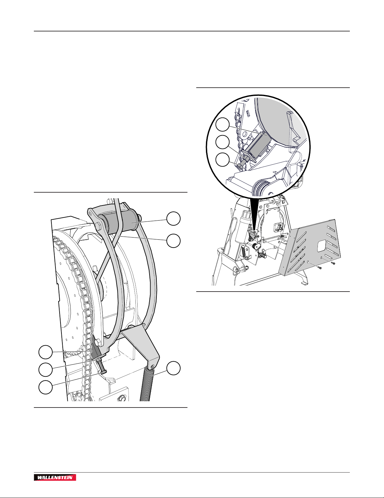
7.7 Drum Brake Adjustment
7.7.1 Winch Drum Brake Operation
The winch brake stops the drum from turning when
there is no tension on the cable and the drum lock is
not engaged. The brake must be set to hold the drum
from freewheeling when the cable is not being pulled
out to avoid tangling the cable.
As the cable is spooled off the drum, it is routed
over the top of the brake assembly arm. The force
of spooling the cable off the drum, moves the arm to
release the brake. When the cable is no longer being
spooled on, the spring pulls the arm back and engages
the brake. The brake must be set to stop the drum from
freewheeling when the cable is not being pulled out to
avoid tangling the cable.
Remove lower protective shield from the front side of
the winch to access brake adjustment.
4
7.7.2 Procedure
1. Loosen jam nut (2) on adjustment bolt.
2. Tighten the adjustment bolt (1) until the brake block
(3) just contacts the drum.
3. Tighten jam nut.
3
2
1
3
2
1
Fig. 40 – Winch Brake
1. Adjuster Bolt
2. Jam Nut
3. Drum Brake Block
4. Brake Arm Cable Roller
5. Cable
6. Spring
5
00607
Fig. 41 – Winch brake Adjust
1. Adjuster Bolt
2. Jam Nut
3. Drum Brake Block
6
00606
39
Page 40

Service and Maintenance
FX66, FX85/R, FX110/R, FX140/R
PTO Skidding Winch
7.8 Cable Install
1. Feed cable through the eye of the cable guide (2)
and over the pulley into the drum.
2. Route cable under the brake arm cable roller (3) on
the drum band coiler.
3. Insert cable through hole in the drum into the
anchor (5).
5
3
2
7.9 Brake and Clutch Rope Routing
1
6
5
4
2
3
1
Fig. 42 – Installing Cable
1. Winch cable
2. Cable Guide
3. Brake Arm Cable Roller
4. Cable Drum
5. Drum Cable Anchor
00609
Fig. 43 – Rope Routing
4
00608
1. Brake Control Rope (white)
2. Clutch Control Rope (green)
3. Tie-off Point
4. Double Pulley
5. Tie-off Point
6. Single Pulley.
40
Page 41
FX66, FX85/R, FX110/R, FX140/R
PTO Skidding Winch
Transporting
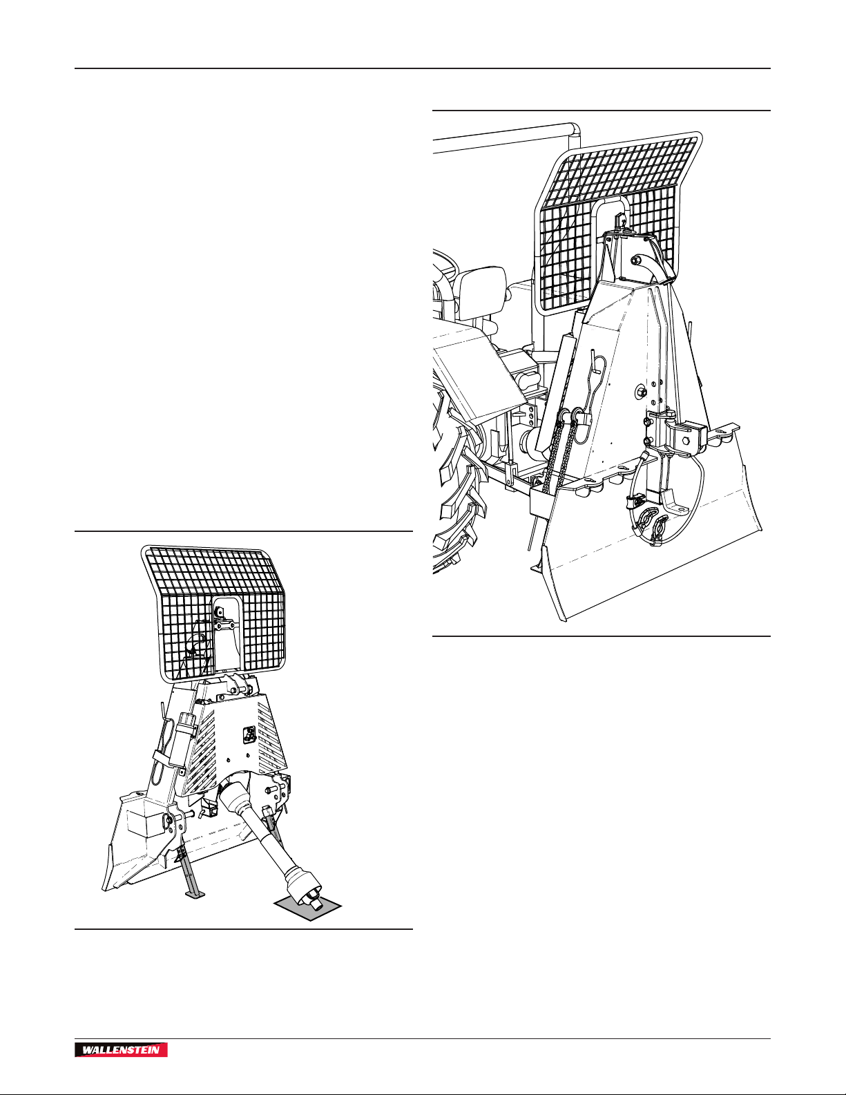
8. Storage
After the season's use or when the machine is not
going be used for a period of time, place the winch in
storage.
Completely inspect all major systems. Replace or
repair any worn or damaged components to prevent
any unnecessary down time at next use.
1. Park the winch away from human activity in a dry,
level area.
2. Lower the winch to the ground. Make sure support
legs are lowered and locked in position. If the
ground is soft, place a board or plate under the
legs.
3. Detach winch from the tractor. Keep the PTO shaft
out of the dirt by resting it on wood blocking.
4. Wash the machine to remove all dirt, mud, and
debris. Inspect all rotating parts and remove any
entangled material.
5. Check the condition of chain and sprockets.
Replace or adjust as required.
9. Transporting
6. If the winch cannot be stored inside, cover with a
waterproof tarp.
00613
00612
Fig. 46 – Winch Attached
• Comply with local laws governing safety and
transporting of machinery on public roads.
• Do not exceed a safe travel speed. Slow down for
rough terrain.
• Be sure the winch is hitched properly to the tractor
and a retainer is used through the mounting pins.
• Never allow riders on the machine.
• Be a safe and courteous driver. Always yield to
oncoming trafc in all situations, including narrow
bridges, intersections, and so on.
• Watch for trafc when near or crossing roadways.
• Do not drink and drive.
Fig. 45 – Storage Position
41
Page 42

Troubleshooting
FX66, FX85/R, FX110/R, FX140/R
PTO Skidding Winch
10. Troubleshooting
If a problem is encountered that is difcult to solve,
even after having read through this troubleshooting
section, contact your local dealer, distributor or
Wallenstein Equipment.
Identify machine serial number. See Serial Number
Location on page 5.
Problem Cause Solution
Cable jammed.
Winch clutch disengaged. Engage clutch.
PTO not operating. Turn tractor PTO drive on.
Clutch brake pads worn out. Replace pads.
Clutch out of adjustment. Adjust clutch.
Cable does not retract.
Cable does not pull out.
Slow cable retraction.
Winch does not lock.
Drive chain comes off. Drive chain too loose.
Cable twists / jams and does
not wind in correctly.
Cable pulls out when clutch
engaged.
Broken PTO shaft shear pin. Replace pin and reduce size of load.
Remote control.
Winch drum lock engaged. Disengage winch lock.
Cable jammed.
PTO shaft speed too slow.
Clutch slipping.
Clutch not engaged. Pull harder on clutch rope.
Clutch brake pads worn out. Inspect or replace brake pads.
Drum lock broken
Winch brake not working properly.
Clutch out of adjustment. Adjust clutch to prevent cable creep.
Disengage winch or release brake,
pull cable out and rewind cable onto
the spool. Check winch brake.
Check transmitter power is on.
Check that receiver power is on.
Check wiring for power into the
receiver.
Check transmitter battery LED status/
error display (ashing).
Check electrical circuit ground.
Check hydraulic system function.
Disengage winch or release brake and
pull cable out. Rewind cable onto the
spool. Check winch brake.
Increase PTO speed (maximum
540 rpm)
Pull harder on clutch rope.
Adjust Clutch.
Clutch brake pads worn. Replace.
Reduce load.
Grease or oil has got on clutch
brake pads, probably resulting from
improper chain lubrication.
Clean or replace clutch brake pads.
Inspect and repair or replace lock
mechanism.
Check the alignment of the chain and
for possible damage. Adjust chain
tension. Replace if necessary
Clean brake block (greasy).
Adjust brake block
Replace brake block (worn out).
Repair damaged brake parts.
42
Page 43

FX66, FX85/R, FX110/R, FX140/R
PTO Skidding Winch
Problem Cause Solution
Winch jerks and shakes while
in operation.
Front end of tractor comes
off ground when winching.
Tractor slides backwards
when winching
Drive chain loose. Check chain tensioner and adjust.
Drive sprocket misaligned. PTO
shaft too long.
Tractor too light in front. Add front end weights.
Parking brake not applied. Apply parking brake.
Winch blade not fully lowered
enough to anchor rmly in the
ground.
Check that PTO shaft is the correct
length.
Lower the winch all way to the ground.
Troubleshooting
43
Page 44

Specications
11. Specications
FX66, FX85/R, FX110/R, FX140/R
PTO Skidding Winch
11.1 Machine Specications
1
Model FX66 FX85 / FX85R FX110 / FX110R FX140 / FX140R
Weight
Machine
Dimensions
L x W x H
Pulling Capacity
Horsepower Range
PTO Input Speed
(Maximum)
Winch Type Mechanical, Dry Disk Clutch – Adjustable
Winch Line Speed
Winch Cable
Type Steel Cable
Length
Maximum Cable
Length Capacity
Diameter
Maximum Input
Torque
Maximum Bare
Drum Pull
Maximum Full
Drum Pull
Hydraulic Flow
Required for
Remote Control
Standard Features
Lower Snatch Block
Available
Accessories
Mounting System
Category
450 lb
204 kg
19" x 40" x 71"
48 x 101 x 180 cm
6,600 lb
2 993 kg
30–60 hp
22.5–45 kW
96–238 ft/min
29–72 m/min
239 ft
73 m
3/8"
9.5 mm
207 lbf•ft
281 N•m
6,671 lb
3 025 kg
2,334 lb
1 058 kg
N/A
2–Keyhole Slots
Rope Controlled
Brake / Clutch
System
Top Cable Pulley
Heavy Duty Safety
Screen
CAT I CAT I CAT I and II
Lower Snatch Block
Dual Position Lower
470 lb
213 kg
27" x 40" x 76"
68 x 101 x 193 cm
8,500 lb
3 855 kg
30–60 hp
13–45 kW
265 lbf•ft
360 N•m
8,553 lb
3 879 kg
2,992 lb
1 357 kg
2–Choker Chains
2–Keyhole Sliders
Trailer hitch
4–Keyhole Slots
Rope Controlled
Brake / Clutch
System
Top Cable Pulley
Heavy Duty Safety
Screen
Link
Self-releasing Directional Pulley
Logging Tongs
Synthetic Rope / Choker
Chainsaw Holder
Choker Chain
28" x 50-1/2" x 79"
71 x 128 x 200 cm
540 rpm
165 ft
50 m
('R'–models only)
Rope Controlled Brake / Clutch System
Lower Snatch Block—Height Adjustable
796 lb
361 kg
11,000 lb
4 989 kg
45–100 hp
34–75 kW
98–253 ft/min
30–77 m/min
207 ft
63 m
7/16"
11 mm
351 lbf•ft
476 N•m
11,130 lb
5 048 kg
3,673 lb
1 666 kg
1–2 gpm
3.8–7.6 Lpm
2–Choker Chain
2–Keyhole Sliders
4–Keyhole Slots
Top Cable Pulley
Heavy Duty Safety Screen
Dual Position Lower Link
898 lb
407 kg
28" x 58-1/2" x 80"
71 x 149 x 203 cm
14,000 lb
6 350 kg
60–140 hp
45–104 kW
98–246 ft/min
30–75 m/min
165 ft
50 m
1/2"
12.7 mm
450 lbf•ft
610 N•m
14,053 lb
6 374 kg
4,733 lb
2 146 kg
Trailer hitch
1. Specications subject to change without notice.
44
Page 45
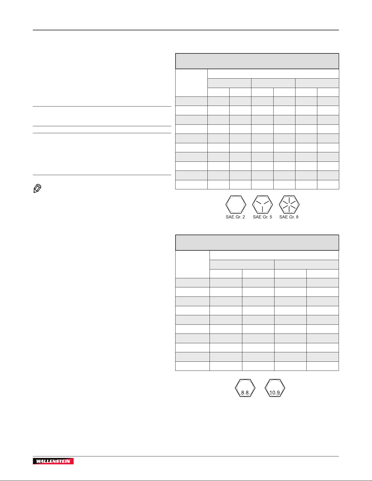
FX66, FX85/R, FX110/R, FX140/R
PTO Skidding Winch
11.2 Bolt Torque
Specications
Checking Bolt Torque
The tables shown give correct torque values for
various bolts and capscrews. Tighten all bolts to
the torque values specied in the table, unless
indicated otherwise. Check tightness of bolts
periodically.
IMPORTANT! If replacing hardware, use
fasteners of the same grade.
IMPORTANT! Torque gures indicated in the
table are for non-greased or non-oiled threads.
Do not grease or oil threads unless indicated
otherwise. When using a thread locker,
increase torque values by 5%.
NOTE:
Bolt grades are identied by their
head markings.
Imperial Bolt Torque Speci cations
Bolt
Diameter
1/4" 6 8 9 12 12 17
5/16" 10 13 19 25 27 36
3/8" 20 27 33 45 45 63
7/16" 30 41 53 72 75 100
1/2" 45 61 80 110 115 155
9/16" 60 95 115 155 165 220
5/8" 95 128 160 215 220 305
3/4" 165 225 290 390 400 540
7/8" 170 230 420 570 650 880
1" 225 345 630 850 970 1320
SAE Gr. 2 SAE Gr. 5 SAE Gr. 8
lbf•ft N•m lbf•ft N•m lbf•ft N•m
Torque Value
Metric Bolt Torque Speci cations
Bolt
Diameter
M3 0.4 0.5 1.3 1.8
M4 2.2 3 3.3 4.5
M6 7 10 11 15
M8 18 25 26 35
M10 37 50 52 70
M12 66 90 92 125
M16 166 225 229 310
M20 321 435 450 610
M30 1,103 1 495 1,550 2 100
M36 1,917 2 600 2,700 3 675
Gr. 8.8 Gr. 10.9
lbf•ft N•m lbf•ft N•m
Torque Value
45
Page 46

Specications
FX66, FX85/R, FX110/R, FX140/R
PTO Skidding Winch
11.3 Hydraulic Fitting Torque
Tightening Flare Type Tube Fittings
1. Check are and are seat for defects that
might cause leakage.
2. Align tube with tting before tightening.
3. Hand-tighten swivel nut until snug.
4. To prevent twisting the tube, use two
wrenches. Place one wrench on the
connector body and tighten the swivel nut
with the second. Torque to values shown.
If a torque wrench is not available, use the FFFT
(Flats From Finger Tight) method.
Hydraulic Fitting Torque
Tube
Size
OD
Inches Inches
3/16 7/16 6 8 2 1/6
1/4 9/16 11–12 15–17 2 1/6
5/16 5/8 14–16 19–22 2 1/6
3/8 11/16 20–22 27–30 1-1/4 1/6
1/2 7/8 44–48 59–65 1 1/6
5/8 1 50–58 68–79 1 1/6
3/4 1-1/4 79–88 107–119 1 1/8
1 1-5/8 117–125 158–170 1 1/8
Values shown are for non-lubricated connections.
Hex
Size
Across
Flats
Torque value
lbf•ft
N•m Flats Turns
Flats From
Finger Tight
46
Page 47

FX66, FX85/R, FX110/R, FX140/R
PTO Skidding Winch
Alphabetical Index
12. Alphabetical Index
A
Attaching Winch to Tractor ..........................................21, 30
Remote Winch Control ................................................. 23
B
Bolt torque ......................................................................... 45
Brake and Clutch Rope Routing ........................................ 40
Break-in ............................................................................. 31
C
Cable Install ...................................................................... 40
Checking Bolt Torque ........................................................ 45
Choker Chains .................................................................. 26
Clutch Adjustment ............................................................. 38
Controls
Choker Chains ............................................................. 26
Forged Cable End ........................................................ 25
Keyhole Sliders ............................................................ 25
Keyhole Slots ............................................................... 25
Remote Winch Control ................................................. 27
Safety Screen .............................................................. 27
Snatch Block ................................................................ 26
Trailer Hitch ................................................................. 26
Winch Clutch ................................................................ 24
Winch Drum Lock ........................................................ 24
D
Decal Information ................................................................ 7
Delivery Inspection Report .................................................. 4
Determine Proper PTO Shaft Length ................................ 22
Drive Chain Lubrication ..................................................... 37
Drive Chain Tension .......................................................... 38
Drum Brake Adjustment .................................................... 39
E
Equipment Safety Guidelines ............................................ 10
F
Familiarization ................................................................... 18
Attaching Winch to Tractor ........................................... 30
Equipment Condition ................................................... 19
Job Site Familiarization ................................................ 18
Machine Break-In ......................................................... 31
Operator Orientation .................................................... 18
Pre-Operation Checklist ............................................... 30
To the New Operator .................................................... 18
Training ........................................................................ 18
Forged Cable End ............................................................. 25
G
Grease Points ................................................................... 36
H
Hand-held Transmitter ....................................................... 27
Hand-held Transmitter – Recharging ................................ 28
Hearing loss .......................................................................11
How to Install Safety Signs ............................................... 17
Hydraulic Fitting Torque .................................................... 46
Hydraulic System Safety ................................................... 35
I
Informative Labels ............................................................... 7
K
Keyhole Sliders ................................................................. 25
Keyhole Slots .................................................................... 25
L
Lower Snatch Block .......................................................... 26
M
Machine Break-In .............................................................. 31
Machine Specications ..................................................... 44
Maintenance Schedule ...................................................... 36
100 hours or Annually .................................................. 36
As required .................................................................. 36
Every 50 hours or weekly ............................................ 36
Every 100 hours or Annually ........................................ 36
O
Operating Instructions ....................................................... 30
Winching Safety ........................................................... 31
Operating Safety ............................................................... 10
Operation
Pre-Operation Checklist ............................................... 30
Skidding ....................................................................... 33
Skidding over Rough Ground ................................. 34
Winching Logs ............................................................. 32
Operator Orientation ......................................................... 18
P
Personal Protective Equipment (PPE) ................................ 9
Pre-start Checklist ............................................................. 30
Product Labels .................................................................... 7
PTO Shaft Connection
Shortening PTO Shaft .................................................. 23
R
Remote Control Operation ................................................ 28
Remote Winch Control ...................................................... 27
Manual Override .......................................................... 28
Synchronize Transmitter and Receiver ........................ 30
Transmitter Sleep Time Programming ......................... 29
Replace Damaged Safety Signs ....................................... 17
S
Safe Condition ...............................................................9, 35
Safety .................................................................................. 8
Equipment Safety Guidelines ...................................... 10
How to Install Safety Signs .......................................... 17
Hydraulic System Safety .............................................. 35
Maintenance Safety ..................................................... 35
Operating Safety .......................................................... 10
Personal Protective Equipment (PPE) ........................... 9
Preparation ...................................................................11
Safety Alert Symbol ....................................................... 8
Safety Training ............................................................. 10
Signal Words ................................................................. 8
Safety Alert Symbol ............................................................. 8
47
Page 48

Alphabetical Index
Safety Notice Labels ........................................................... 7
Safety Screen .................................................................... 27
Safety Sign Explanations .................................................. 13
Safety Signs ...................................................................... 13
Safety Training .................................................................. 10
Serial number ...................................................................... 5
Service and Maintenance .................................................. 35
Brake and Clutch Rope Routing .................................. 40
Cable Install ................................................................. 40
Clutch Adjustment ........................................................ 38
Drive Chain Lubrication ............................................... 37
Drive Chain Tension ..................................................... 38
Drum Brake Adjustment ............................................... 39
Grease Points .............................................................. 36
Maintenance Safety ..................................................... 35
Maintenance Schedule ................................................ 36
Shortening PTO Shaft ....................................................... 23
Sign-off form ...................................................................... 12
Skidding ............................................................................ 33
Skidding over Rough Ground ............................................ 34
Specications .................................................................... 44
FX66 ............................................................................ 44
FX85 / FX85R .............................................................. 44
FX110 / FX110R .......................................................... 44
FX140 / FX140R .......................................................... 44
Hydraulic Fitting Torque ............................................... 46
Storage .............................................................................. 41
Synchronize Transmitter and Receiver ............................. 30
FX66, FX85/R, FX110/R, FX140/R
PTO Skidding Winch
T
Tractor Gets Stuck ............................................................ 34
Trailer Hitch ....................................................................... 26
Transmitter Sleep Time Programming .............................. 29
Transporting ...................................................................... 41
Troubleshooting Guide ...................................................... 42
W
Warranty .............................................................................. 6
Winch Brake Operation ..................................................... 39
Winch Clutch ..................................................................... 24
Winch Drum Lock .............................................................. 24
Winching Logs ................................................................... 32
Winch Safety ..................................................................... 31
48
Page 49

Page 50

www.wallensteinequipment.com
 Loading...