

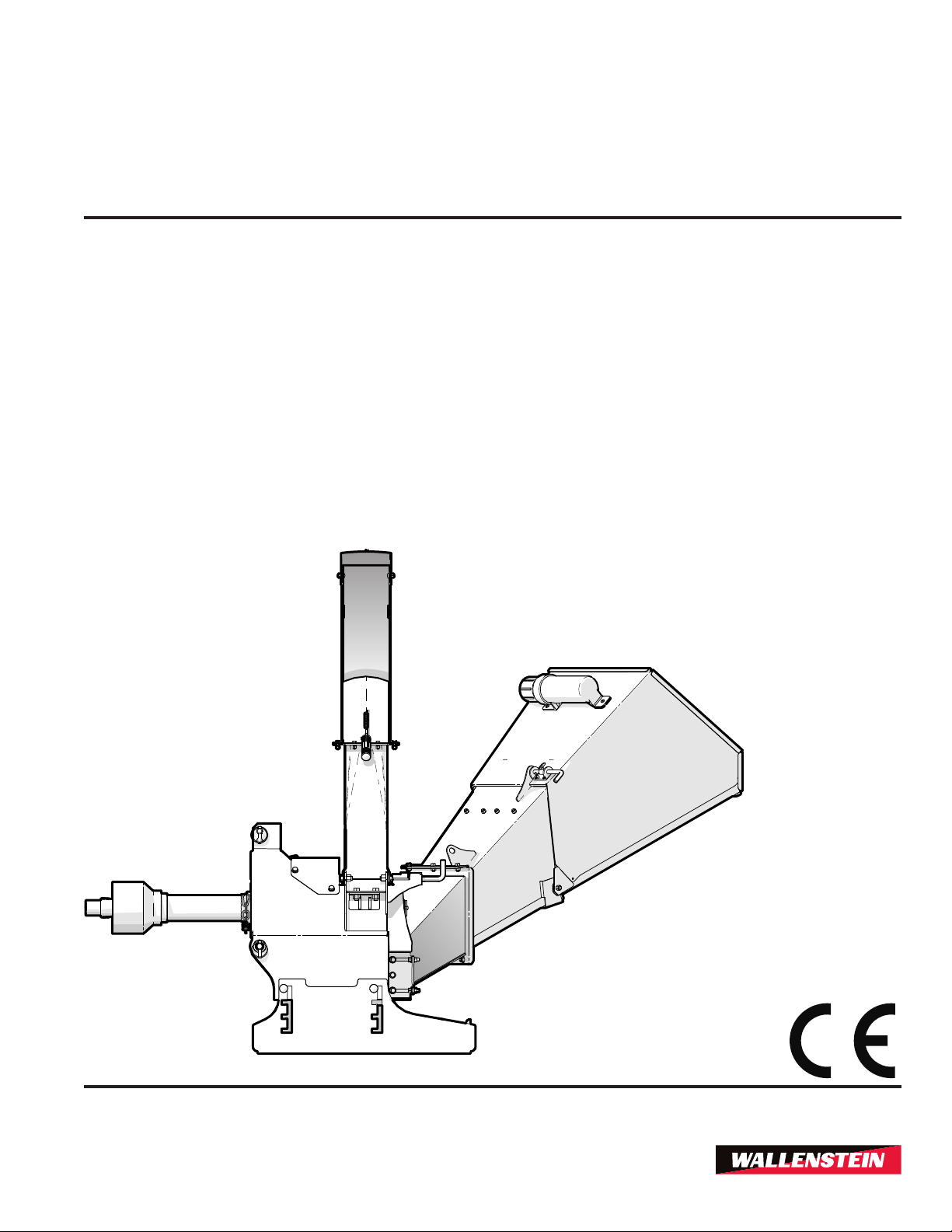
OPERATOR'S MANUAL
BX
BX
BX
BX
3PH Self-feed Chipper
36S
52S
72S
102S

Introduction
1. Introduction
Congratulations on your choice of a Wallenstein BX
Series 3 Point Hitch Wood Chipper to compliment your
operation. This equipment has been designed and
manufactured to meet the needs of a discerning timber
or landscaping industry.
Safe, efcient and trouble free operation of your
Wallenstein Wood Chipper requires that you and
anyone else who will be using or maintaining the
chipper, read and understand the Safety, Operation,
Maintenance and Trouble Shooting information
contained within the Operator's Manual.
This manual covers all variations of the Wallenstein
3-Point Hitch Wood Chipper – BX Series. Your
particular model may vary from the illustrations shown
depending on your options package.
Keep this manual handy for frequent reference and
to pass on to new operators or owners. Call your
Wallenstein dealer or the Distributor if you need
assistance, information or additional copies of the
manuals.
3PH Self-feed Chipper
WARNING!
Do not attempt to start or operate the machine
without thoroughly reviewing this manual for
safe and proper operation.
Keep this manual with the machine at all times.
BX36S
W034
Wallenstein Equipment Inc. • © 2018
This manual covers models:
BX36S
BX52S
BX72S
BX102S
2

BX36S
3PH Self-feed Chipper
Introduction
Table of Contents
1. Introduction ............................................................2
2. Label Information ...................................................4
3. Warranty .................................................................5
4. Delivery Inspection Report ...................................6
5. Serial Number Location ........................................7
6. Safety ......................................................................8
6.1 Safety Alert Symbol .........................................8
6.2 Why is SAFETY important? .............................8
6.3 Signal Words ...................................................8
6.4 General ............................................................9
6.5 Safety Do's and Don'ts ....................................9
6.6 Safe Condition ................................................9
6.7 Operating Safety ............................................10
6.8 Equipment Safety Guidelines ........................11
6.9 Safety Training ..............................................12
6.10 Maintenance Safety .......................................12
6.11 Storage Safety ...............................................13
6.12 Sign-Off Form ................................................13
7. Safety Signs ........................................................14
7.1 Safety Sign Locations ....................................14
7.2 Replace Damaged Safety Signs ....................18
7.3 How to Install Safety Signs ............................18
8. Familiarization......................................................18
8.1 To the New Operator or Owner .....................18
8.2 Operator Orientation ......................................18
8.3 Machine Components ....................................19
9. PTO Shaft Connection .........................................21
9.1 Determine Correct PTO Shaft Length ...........21
10. Attaching Chipper to Tractor ............................22
10.1 Procedure ......................................................22
11. Controls ..............................................................24
11.1 Discharge Chute ............................................24
11.2 Hood Deector ...............................................25
12. Operation ............................................................26
12.1 Be Prepared ..................................................26
12.2 Machine Set-up .............................................26
12.3 Adjust Ski Height ..........................................27
12.4 Machine Break-In ..........................................28
12.5 Pre-Operation Checklist ................................28
12.6 Starting Procedure .........................................29
12.7 Stopping ........................................................29
12.8 Stopping in an Emergency ............................29
12.9 Chipping Operation ........................................29
13. Transporting .......................................................31
13.1 Prepare for transport .....................................31
13.2 Stow the Feed Table .....................................31
14. Storage ...............................................................32
14.1 Placing Chipper in Storage ............................32
14.2 Removing from Storage .................................32
15. Service and Maintenance ..................................33
15.1 Service ...........................................................33
15.2 Greasing ........................................................33
15.3 Maintenance Schedule ..................................38
15.4 Driveline Maintenance ...................................40
15.5 Shear Pin .......................................................40
15.6 Rotor Lock Pin ...............................................41
15.7 Twig Breaker .................................................41
15.8 Rotor Blades ..................................................42
15.9 Ledger Blades ...............................................43
16. Trouble Shooting ...............................................45
17. Specications ....................................................46
17.1 Bolt torque .....................................................48
18. Index ...................................................................49
3
Label Information
BX36S
3PH Self-feed Chipper
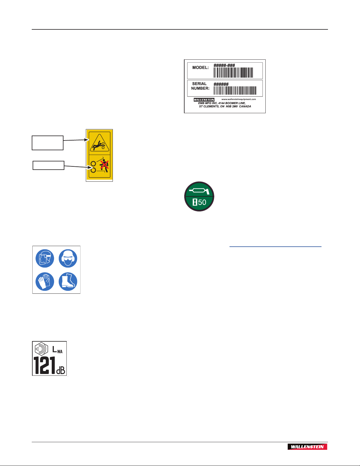
2. Label Information
As you begin to get familiar with your Wallenstein
product, you will notice that there are numerous labels
located on the machine. Here is a brief explanation
of what they are for and how to read them. There are
different types of labeling for safety, information, and
product identication.
Safety Labels are pictorial with a yellow background
and generally 2 panel. The top panel shows the safety
alert (the potential hazard) and the bottom panel shows
the message (how to avoid the hazard).
Safety
alert
Message
Z94207
Safety Notice Labels are pictorial with a blue
background and generally rectangular with single or
multiple symbols. The label illustrates requirements
for safe operation (safety equipment, housekeeping
and so on). These labels are accompanied by detailed
instructions in the owner's manual, with the label
illustrated alongside.
Product Labels are associated with the product and
carry various messages such as model, serial number,
and so on.
Maintenance Labels are associated with the product
and carry various messages. They are generally
pictorial. They may be round or rectangular, have
a green background and can vary to the number of
panels. The label may illustrate the type maintenance
and frequency in time between services. Labels are
accompanied by detailed instructions in the owners
manual, with the label illustrated alongside.
See the section on safety signs for safety label
denitions. For a complete illustration of labels and
label locations, download the parts manual for your
model product at www.wallensteinequipment.com.
Informative Labels are generally pictorial with a white
background and can vary to the number of panels.
The label will illustrate the function of a feature and is
accompanied by detailed instructions in the owner's
manual, with the label illustrated alongside.
4

BX36S
3PH Self-feed Chipper
Warranty
3. Warranty
WARRANTY
Effective on products retailed on or after January 1, 2015.
Register your product online at www.wallensteinequipment.com
within 30 days of purchase to activate warranty.
This product is warranted to be free of defects in materials and workmanship
under normal use and service, for a period of
Five Years for Consumer
Two Years for Commercial / Rental
from the date of purchase, when operated and maintained in accordance with the Operating and Maintenance Instructions
supplied with this unit. Warranty is limited to the repair of the product and/or replacement of parts.
This warranty does not cover the following items:
1) Machines or parts lost or damaged during shipment.
2) Normal maintenance or adjustments after initial pre-service and set up is completed.
3) Normal replacement of service items.
4) Accessory items / parts not supplied by Wallenstein Equipment Inc.
5) Damages resulting from:
•
•
• use of parts or after market accessories other than genuine Wallenstein Equipment Inc. parts
•
• any device or accessories installed by parties other than an authorized Wallenstein dealer or distributor
Engines
Engine warranty must be registered at the engine manufacturer’s website. For service, contact your local engine dealer.
Under no circumstances will the manufacturer be liable for any consequential damage or expense of any kind, including loss
the maintenance of the product.
This warranty is extended only to the original purchaser and is not transferable. Warranty is void if repairs are attempted by
anyone other than a Wallenstein Authorized Service Centre.
ized dealers are authorized to make repairs to the product or affect the replacement of defective parts, which will be done at
no charge within a reasonable time after the receipt of the product. Unit or parts shall be returned at the customer’s expense
to the Authorized Service Center. Damage in transit is not covered by warranty. Include the original purchase receipt with
The distributor’s liability under warranty is limited to the repair of the product and/or replacement of parts and is given to the
purchaser in lieu of all other remedies including incidental and consequential charges. There are no warranties, expressed
Wallenstein Equipment Inc.
7201 Line 86, Wallenstein ON Canada N0B 2S0
Phone: 519-699-9283 Fax: 519-699-4146 Attention Warranty Dept.
Email: warranty@wallensteinequipment.com
Revised Aug-2018
WARRANTY VOID IF NOT REGISTERED
-
5

Delivery Inspection Report
3PH Self-feed Chipper
4. Delivery Inspection Report
WALLENSTEIN
BX S–Series 3 Point Hitch Wood Chipper
To activate warranty, register your product online at:
http://www.wallensteinequipment.com
This form must be lled out by the dealer and signed by both the dealer and the customer at the time of delivery.
BX36S
_________________________________________
Customer’s Name
_________________________________________
Contact Name
_________________________________________
Dealer Name
(_________)_______________________________
Phone Number
_________________________________________
Serial Number
__________ /__________ /__________
Delivery Date (dd/mm/yy)
Pre-delivery Inspection
Inspect for damage from shipping. Immediately contact the
shipping company if damage is found.
BX S–Series Wood Chipper
Check blade clearance and that rotor turns freely
Check that discharge and de ector move freely
Check that all fasteners are tight
Check that lock pins align and move freely
Check all grease points and lubricate pivot points
Review operating and safety instructions in the Operator's
Manual
Safety Checks
All Safety Decals Installed
Guards and Shields Installed and Secured
Check that the Slow Moving Vehicle sign is installed
Check that retainers are installed through hitch points
Review operating and safety instructions in the Operator's
Manual
I have thoroughly instructed the buyer on the equipment care, adjustments, safe operation and applicable warranty policy and reviewed the manuals.
_________________________________________
Dealer’s Rep. Signature
__________ /__________ /__________
Delivery Date (dd/mm/yy)
The product manuals have been received by me and
I have been thoroughly instructed as to care, adjustments, safe operation and applicable warranty policy.
_________________________________________
Owner's Signature
__________ /__________ /__________
Delivery Date (dd/mm/yy)
6
BX36S
3PH Self-feed Chipper
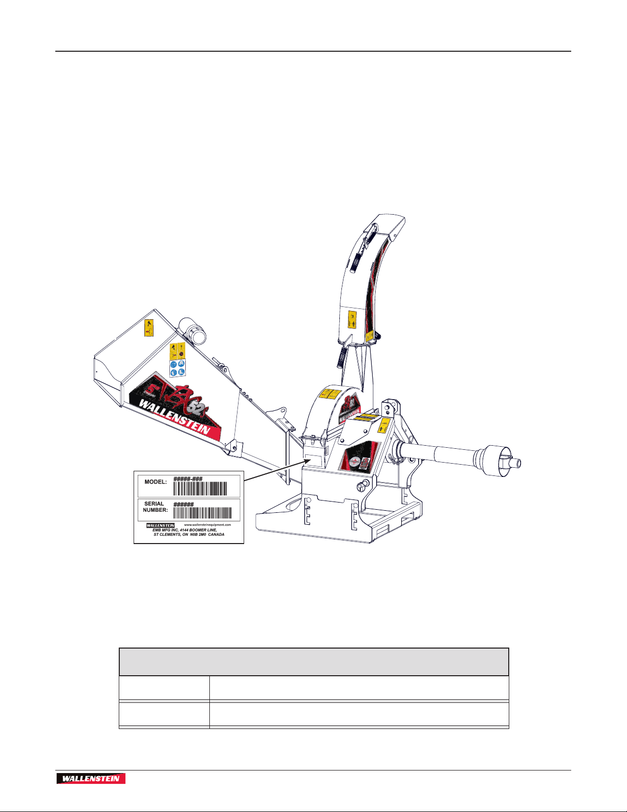
5. Serial Number Location
Always give your dealer the serial number of your
Wallenstein product when ordering parts or requesting
service or other information. The Serial Number Plate
location is shown in the illustration.
Please record the product Model and Serial
Number in the space provided bellow for easy
reference.
The BX52S is shown, however the serial plate location
is the same for all BXS Series machines.
Serial Number Location
Fig. 1 – Serial Number Plate Location (Typical)
(BX52S shown)
Model:
Serial Number:
Record Product Information Here
7

Safety
6. Safety
6.1 Safety Alert Symbol
This Safety Alert Symbol means:
ATTENTION! BE ALERT!
YOUR SAFETY IS INVOLVED!
BX36S
3PH Self-feed Chipper
The Safety Alert Symbol identies important
safety messages on the Wallenstein Wood
Processor and in the manual. When
you see this symbol, be alert to the
possibility of personal injury or death.
Follow the instructions in the safety
message.
6.2 Why is SAFETY important?
Three Big Reasons:
• Accidents Disable and Kill
• Accidents Cost
• Accidents Can Be Avoided
6.3 Signal Words
The signal words DANGER, WARNING and CAUTION
determine the seriousness level of the warning
messages in this manual. The appropriate signal word
for each message in this manual has been selected
using the following guidelines:
DANGER –
Indicates an imminently hazardous situation that, if
not avoided, WILL result in death or serious injury.
This signal word is to be limited to the most extreme
situations typically for machine components which, for
functional purposes, cannot be guarded.
WARNING –
Indicates a potentially hazardous situation that, if not
avoided, COULD result in death or serious injury, and
includes hazards that are exposed when guards are
removed. It may also be used to alert against unsafe
practices.
CAUTION –
Indicates a potentially hazardous situation that, if not
avoided, MAY result in minor or moderate injury. It may
also be used to alert against unsafe practices.
IMPORTANT – To avoid confusing equipment
protection with personal safety messages, a signal
word IMPORTANT indicates a situation that if not
avoided, could result in damage to the machine.
NOTE:
(plus text) – indicates an additional
explanation for an element of information.
8
BX36S
3PH Self-feed Chipper
Safety
6.4 General
YOU are responsible for the SAFE operation and
maintenance of your Wallenstein Trailer Wood
Processor. YOU must ensure that you and anyone
else who is going to use, maintain or work around
the Wood Processor be familiar with the operating
and maintenance procedures and related SAFETY
information contained in this manual. This manual
will take you step-by-step through your working day
and alerts you to all good safety practices that should
be used while using your Wallenstein Trailer Wood
Processor.
Remember, YOU are the key to safety. Good safety
practices not only protect you but also the people
around you. Make these practices a working part of
your safety program. Be certain that EVERYONE
using this equipment is familiar with the recommended
operating and maintenance procedures and follows
all the safety precautions. Most accidents can be
prevented.
Do not risk injury or death by ignoring good safety
practices.
6.5 Safety Do's and Don'ts
• DO give operating instructions to
operators or employees before
allowing them to operate the
machine, and REVIEW annually
thereafter.
• DO read and understand ALL Safety and Operating
instructions in the manual and follow them. Most
accidents can be avoided. The most important
safety device on this equipment is a SAFE
operator.
• DO review safety related items annually with all
personnel who will be operating or performing
maintenance.
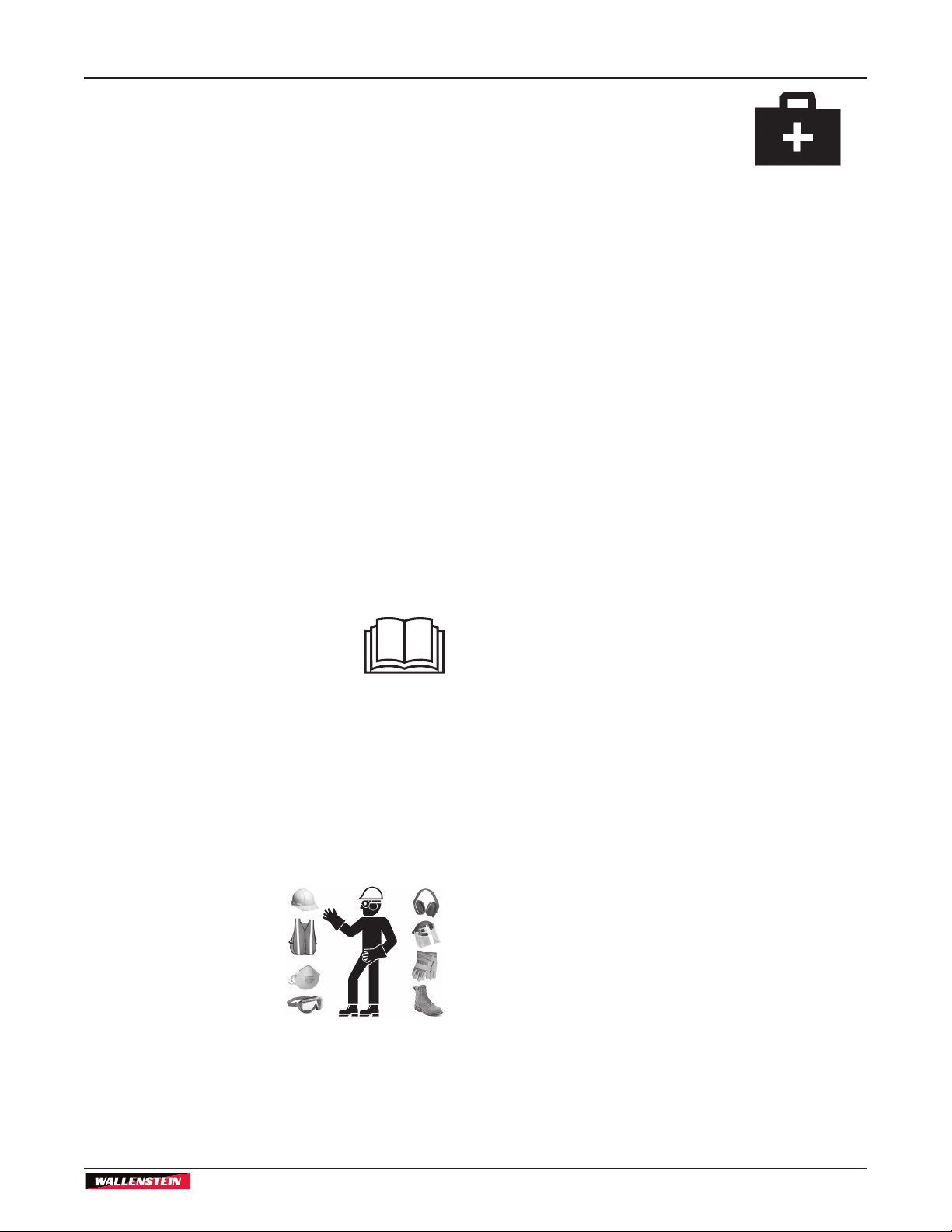
• DO have a rst-aid kit available
for use should the need arise and
know how to use it.
• DO read and understand all safety signs located
on the machine before using, maintaining,
adjusting or cleaning the grapple.
• DO inspect and secure all guards before starting.
• DO check cables, chains and chutes, that they are
clear of debris prior to starting the machine.
6.6 Safe Condition
Always set the machine in a Safe Condition before
performing any service, maintenance work, storage
preparation, or hooking up.
Placing the machine in a Safe Condition involves
performing the following:
- Disengage the PTO.
- Shut off the tractor engine.
- Make sure all components have stopped
moving.
- Remove and retain ignition key.
- Block and chock the tractor wheels.
- Set rotor lock if required.
- Point discharge chute away from operator
working area.
- Ensure the adjustable ski base is sitting on the
ground
• DO wear appropriate
Personal Protective
Equipment (PPE). This
equipment includes
but is not limited to the
following:
- A hard hat
- Heavy gloves
- Hearing Protection
- Respirator or lter mask
- Protective shoes with slip resistant soles
- Protective glasses, goggles or face shield
9

Safety
BX36S
3PH Self-feed Chipper
• DO have a re extinguisher available for
use should the need arise and know how
to use it.
• DO think SAFETY! Work SAFELY!
• DO NOT expect a person who has not read and
understood all use and safety instructions to
operate the machine. An untrained operator is not
qualied and exposes himself and bystanders to
possible serious injury or death. It is the owners
responsibility to the operator to ensure familiarity
and understanding of the machine.
• DO NOT modify the equipment in any way.
Unauthorized modication may impair the function
and/or safety and could affect the life of the
equipment.
• DO NOT allow riders during transport.
• DO NOT risk injury or death by ignoring good
safety practices.
6.7 Operating Safety
• Read and heed the safety signs on the 3 Point
Hitch Wood Chipper. Clean or replace all
safety signs if they cannot be clearly read and
understood. They are there for your safety, as
well as the safety of others. The safe use of this
machine is strictly up to you, the operator.
• Study this manual to make sure you have all safety
equipment attached. All things with moving parts
are potentially hazardous. There is no substitute for
a cautious, safe-minded operator who recognizes
potential hazards and follows reasonable safety
practices. The manufacturer has designed this 3
Point Hitch Wood Chipper to be used with all its
safety equipment properly attached, to minimize
the chance of accidents.
• Close and secure rotor cover before operating.
• Close and secure all guards, deectors and shields
before starting and operating.
• Read and understand operator's manual before
starting. Review safety instructions annually.
• Use Personal protection equipment including
hearing protection, hard hat, safety glasses, safety
shoes, and gloves during assembly, installation,
operation, adjustment, maintaining, repairing,
removal, or moving of this equipment. Do not allow
long hair, loose-tting clothing, or jewelry to be
around moving parts.
• Keep hydraulic lines and ttings tight, in good
condition and free of leaks.
• Never place any part of your body where it would
be in danger if movement of equipment should
occur during assembly, installation, operation,
maintenance, repairing, unplugging or moving.
• Turn machine off, stop and disable engine, remove
and retain ignition key, set park brake and wait
for all moving parts to stop before servicing,
adjusting, repairing or unplugging the chipper.
Inspect machine for damaged or loose parts before
resuming work.
• Do not run machine inside a closed building to
prevent asphyxiation from engine exhaust.
• Use care when feeding material into chipper. Do
not put metal, bottles, cans, rocks, glass or other
foreign material into the wood chipper. If these
materials enter the chipper, stop machine, turn
engine off and remove ignition key before clearing
the object.
10

BX36S
3PH Self-feed Chipper
Safety
• Never consume alcoholic beverages or use
drugs which can impair alertness or coordination
while operating this equipment. Consult your
doctor about operating this machine while taking
prescription medications.
• Do not allow riders on this machine at any time.
There is no safe place for any riders.
• Never allow children or unauthorized people to
operate or be around this machine.
• Keep children and persons unfamiliar with
machine operation away. The operator should be
a responsible, physically able person trained in
equipment operation. If the elderly are assisting
with work, their physical limitations need to be
recognized and accommodated.
• Do not reach into rotor or feed hopper openings
when the engine is running. Install and secure
access covers before starting engine.
• Keep the working area clean and free of debris to
prevent tripping. Operate only on level ground.
• Do not point discharge at people, animals or
buildings. Rotor can expel wood chips fast enough
to cause injury.
• Do not move or transport chipper when the rotor is
turning.
• Do not exceed a safe travel speed when
transporting.
• Keep chipper resting on the ground during
operation. Using the chipper while raised off the
ground is dangerous and will result in damage to
the machine, and potential personal injury.
• Never have the exit chute pointing towards the
hopper or operator working area. Chips can come
out of the chute with enough force to cause injury.
6.8 Equipment Safety Guidelines
Safety of the operator and bystanders is one of the
main concerns in designing and developing equipment.
However, every year many accidents occur which
could have been avoided by a few seconds of thought
and a more careful approach to handling equipment.
You, the operator, can avoid many accidents by
observing the following precautions in this section.
To avoid personal injury or death, study the following
precautions and insist those working with you, or for
you to follow them.
In order to provide a better view, certain photographs
or illustrations in this manual may show an assembly
with a safety shield removed. However, equipment
should never be used in this condition. Keep all shields
in place. If shield removal becomes necessary for
repairs, replace the shield prior to use.
1. Replace any safety sign or instruction sign that is
not readable or is missing. Location of such safety
signs is indicated in this manual.
2. Do not modify the equipment in any way.
Unauthorized modication may result in serious
injury or death and may impair the function and life
of the equipment.
3. In addition to the design and conguration of this
implement, including Safety Signs and Safety
Equipment, hazard control and accident prevention
are dependent upon the awareness, concern,
prudence, and proper training of personnel
involved in the operation, transport, maintenance,
and storage of the machine. Refer also to Safety
Messages and operation instruction in each of the
appropriate sections of the tractor and machine
manuals. Pay close attention to the Safety Signs
afxed to the tractor and the machine.
4. Never exceed the limits of a piece of machinery.
If its ability to do a job, or to do so safely is in
question – DO NOT TRY IT..
11

Safety
BX36S
3PH Self-feed Chipper
6.9 Safety Training
1. Safety is a primary concern in the design and
manufacture of our products. Unfortunately, our
efforts to provide safe equipment can be wiped
out by a single careless act of an operator or
bystander.
2. In addition to the design and conguration of
equipment, hazard control and accident prevention
are dependent upon the awareness, concern,
prudence and proper training of personnel involved
in the operation, transport, maintenance and
storage of this equipment.
3. The best safety feature is an
informed, careful operator—we
ask you to be that kind of an
operator. It is the operator's
responsibility to read, understand
and follow ALL safety and
operation instructions in the
manual. Accidents can be
avoided.
4. Working with unfamiliar equipment can lead
to careless injuries. Read this manual before
assembly or using the machine to acquaint
yourself with it. If this machine is used by any
person other than yourself, or is loaned or rented,
it is the machine owner's responsibility to make
certain that prior to using, the operator:
- reads and understands the owner's manual
- is instructed in safe and proper use of the
equipment
- understands and knows how to perform the
Safe Condition procedure
5. Train all new personnel and review instructions
frequently with existing workers. Be certain only
a properly trained and physically able person will
use the machinery. A person who has not read and
understood all use and safety instructions is not
qualied to use the machine. An untrained operator
exposes himself and bystanders to possible
serious injury or death. If the elderly are assisting
with the work, their physical limitations need to be
recognized and accommodated.
6.10 Maintenance Safety
Place the machine in a Safe Condition before
performing any service, maintenance work or storage
preparation. See Safe Condition on page 9
Good maintenance is your responsibility. Poor
maintenance is an invitation to trouble.
Follow good shop practices.
• Keep service area clean and
dry.
• Be sure electrical outlets and
tools are properly grounded.
• Use adequate light for the
job at hand.
• Make sure there is plenty of ventilation. Never
operate the engine of the towing vehicle in a
closed building. The exhaust fumes may cause
asphyxiation.
• Before working on this machine, set the brake and
turn the engine off.
• Never work under equipment unless it is blocked
securely.
• Always use personal protection devices such as
eye, hand and hearing protectors, when performing
any service or maintenance work. Use heavy or
leather gloves when handling blades.
• Where replacement parts are necessary for
periodic maintenance and servicing, genuine
factory replacement parts must be used to restore
your equipment to original specications. The
manufacturer will not be responsible for injuries or
damages caused by use of unapproved parts and/
or accessories.
• A re extinguisher and rst aid kit should be kept
readily accessible while performing maintenance
on this equipment.
6. Know your controls and how to stop the machine
and the tractor quickly in an emergency. Read this
manual thoroughly..
• Periodically tighten all bolts, nuts and screws and
check that all electrical and fuel connections are
properly secured.
• When completing a maintenance or service
function, make sure all safety shields and devices
are installed before placing unit in service.
12

BX36S
3PH Self-feed Chipper
Safety
6.11 Storage Safety
• Store the unit in an area away from human activity.
• Do not allow children to play on or around the
stored machine.
• Store the unit in a dry, level area. Support the
frame with planks if required.
• Transport Safety
• Comply with state and local laws governing safety
and transporting of machinery on public roads.
• Check that all the lights, reectors and other
lighting requirements are installed and in good
working condition.
6.12 Sign-Off Form
Wallenstein follows the general Safety Standards
specied by the American Society of Agricultural and
Biological Engineers (ASABE) and the Occupational
Safety and Health Administration (OSHA). Anyone
who will be using and/or maintaining the 3 Point
Hitch Wood Chipper must read and clearly
understand ALL Safety, Usage and Maintenance
information presented in this manual.
• Do not exceed a safe travel speed. Slow down for
rough terrain and cornering.
• Fold up and secure feed hopper before moving or
transporting.
• Be sure the machine is hitched correctly to the
tractor and a retainer is used through the mounting
pins.
• Do not drink and drive.
• Be a safe and courteous driver. Always yield to
oncoming trafc in all situations, including narrow
bridges, intersections, and so on. Watch for trafc
when operating near or crossing roadways.
• Never allow riders on the machine.
Make these periodic reviews of SAFETY and
OPERATION a standard practice for all of your
equipment. We feel that an untrained operator is
unqualied to use this machine.
A sign-off sheet is provided for your record keeping to
show that all personnel who will be working with the
equipment have read and understand the information
in the Operator’s Manual and have been instructed in
the operation of the equipment.
Do not use or allow anyone else to use this chipper
until such information has been reviewed. Annually
review this information before the season start-up.
Sign-off Form
Date Owner Employee
13
Safety Signs
BX36S
3PH Self-feed Chipper
7. Safety Signs
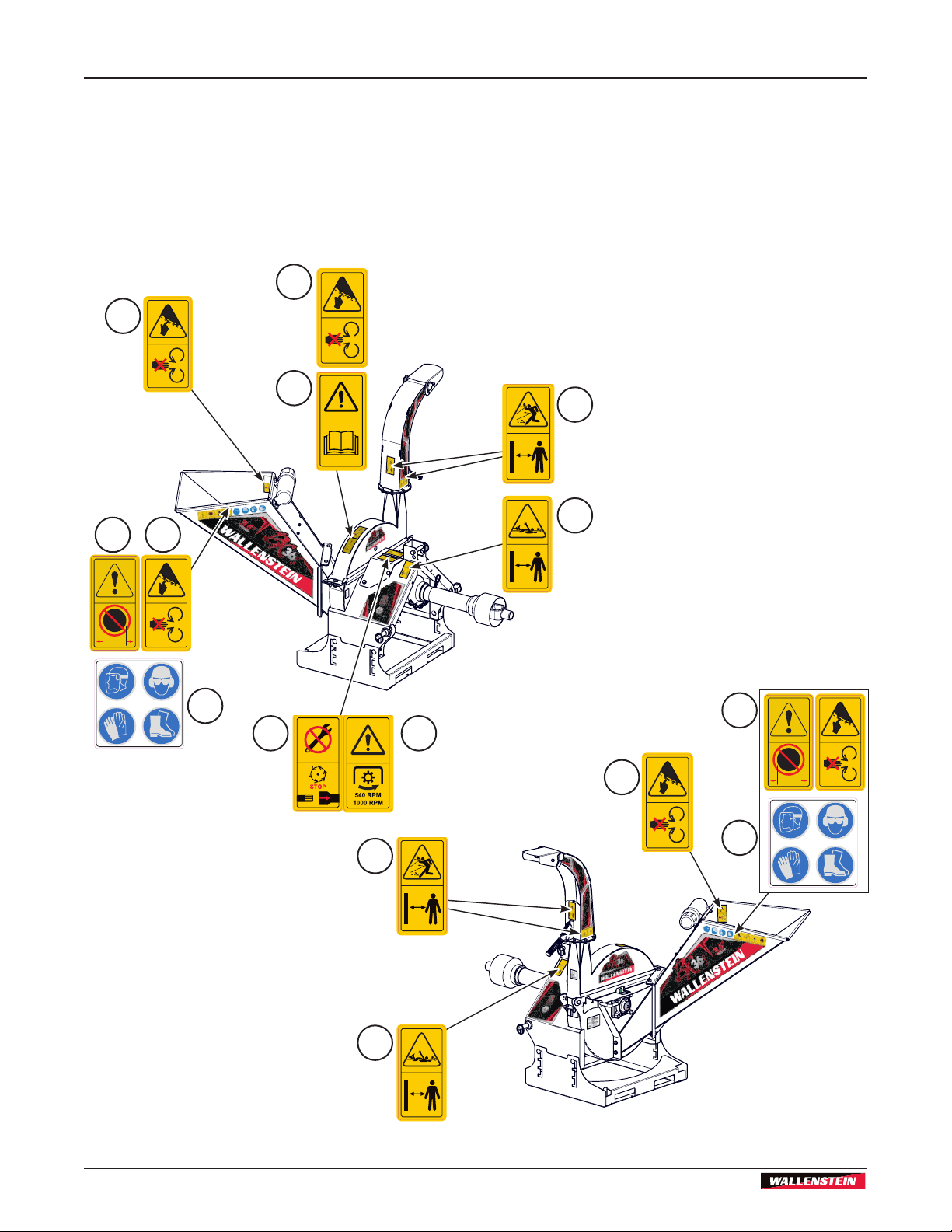
7.1 Safety Sign Locations
The types of safety signs and locations on the
equipment are shown in the illustrations that follow.
Good safety requires that you familiarize yourself with
1
1
5
7
1
the various safety signs, the type of warning and the
area, or particular function related to that area, that
requires your SAFETY AWARENESS.
Think SAFETY! Work SAFELY!
7.1.1 Model BX36S
2
3
75mm
3.0”
Z94232
8
7
4 6
1
75mm
3.0”
Z94232
8
2
3
Fig. 2 – BX36S Safety Decals
14
BX36S
3PH Self-feed Chipper
Safety Signs
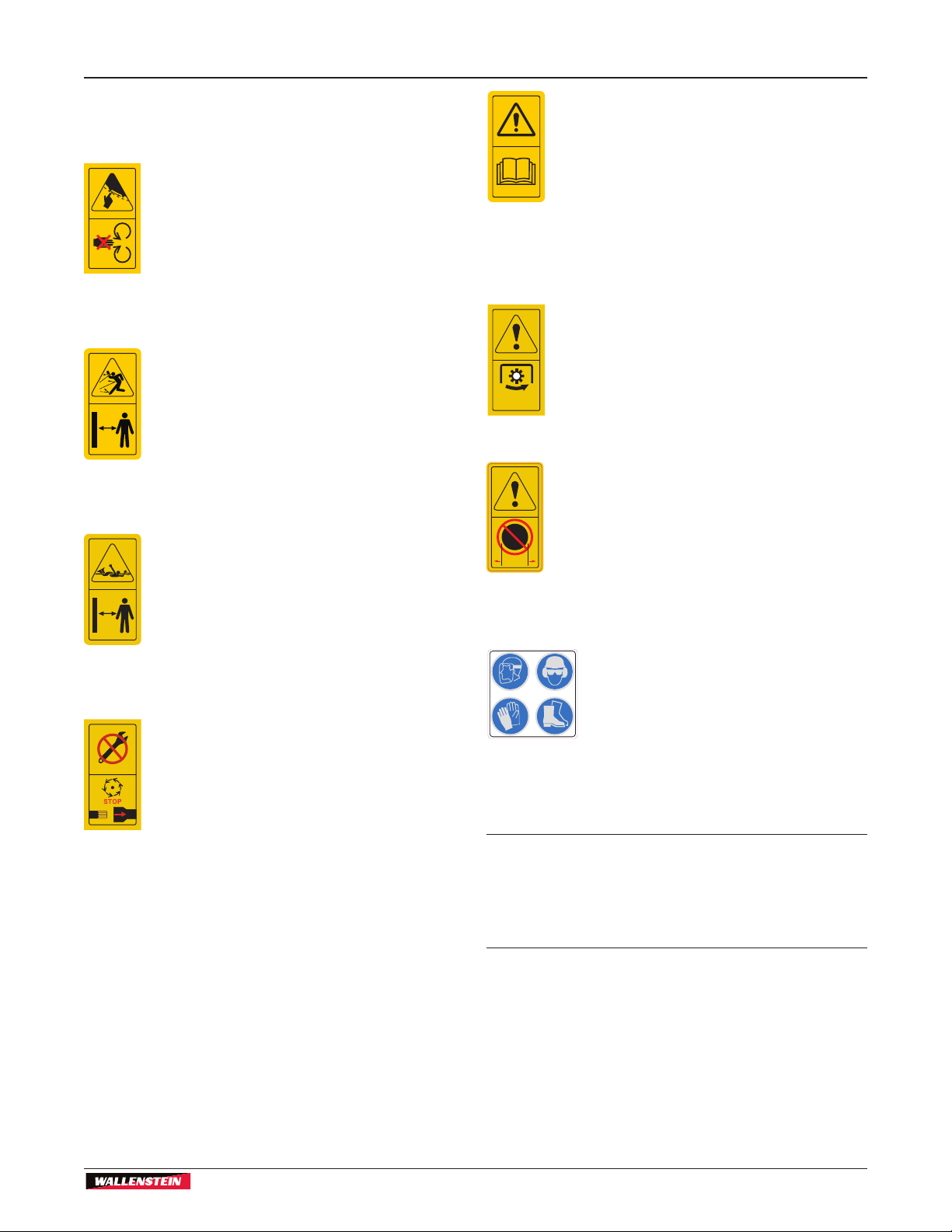
BX36S Safety Sign Explanations
Caution
1. Keep hands and feet out of inlet and
discharge openings while machine is
operating to avoid serious personal
injury. Wait for all moving parts to come
to a complete stop before clearing
obstructions.
Caution:
2. Flying objects. Be aware of and stay
clear of material discharge chute.
Machine can expel wood chips fast
enough to cause injury. Do not point
discharge at people, animals or
buildings.
Caution:
3. Rotating driveline, entanglement danger
present. Keep hands, loose clothing,
and long hair away from driveline while
it is rotating.
Z94118
540 RPM
1000 RPM
3.0”
75mm
Caution
5. Read and understand ALL safety
and operating instructions in the
manual. Read and understand ALL
safety labels located on the machine.
The most important safety device on
this equipment is an informed SAFE
operator.
Caution:
6. Ensure the drive line is rotating in the
proper direction at the rated RPM.
Z94240
Caution:
7. Maximum material size.
Z94232
8. Always wear appropriate Personal
Protective Equipment (PPE) when
operating this machine.
Caution:
4. When performing any maintenance
on the chipper ensure you stop and
disengage the PTO. Potential for
Z94241
serious injury or death if the PTO is not
stopped and disengaged.
IMPORTANT! If safety signs have been damaged,
removed, become illegible or parts replaced
without safety signs, new signs must be applied.
New safety signs are available from your
authorized dealer.
15
Safety Signs
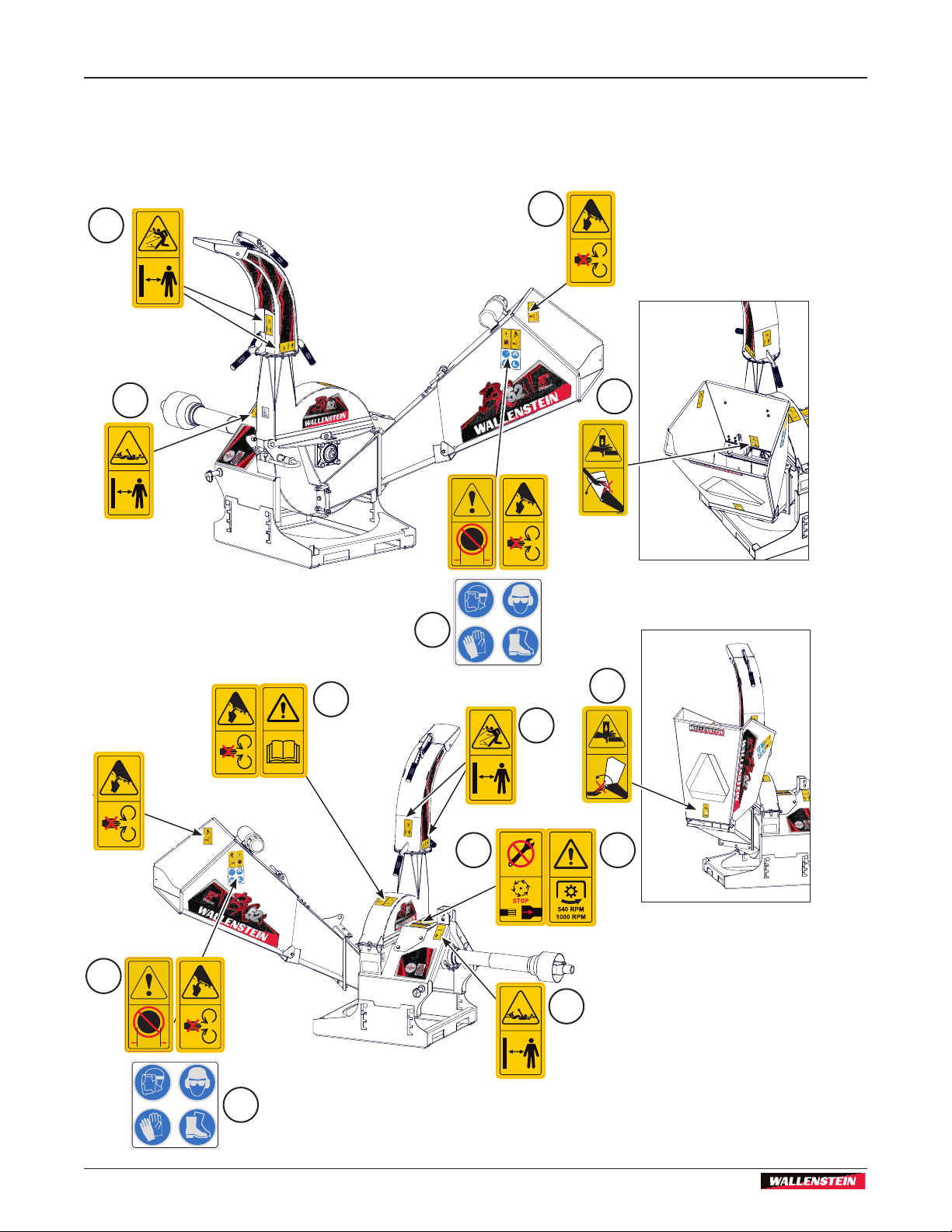
7.1.2 Models BX52S, BX72S, and
BX102S
The BX52S is illustrated. Labels and locations are the
same for the BX72S and BX102S models.
2
BX36S
3PH Self-feed Chipper
1
3
3.0”
75mm
Z94232
7
9
6
5
2
Z94242
10
75mm
4
8
3
3.0”
Z94232
9
Fig. 3 – BX52S, BX72S and BX102S Safety Decals
16

BX36S
3PH Self-feed Chipper
Safety Signs
BX52S, BX72S and BX102S Safety Sign
Explanations
Caution
1. Keep hands and feet out of inlet and
discharge openings while machine is
operating to avoid serious personal
injury. Wait for all moving parts to come
to a complete stop before clearing
obstructions.
Caution:
2. Flying objects. Be aware of and stay
clear of material discharge chute.
Machine can expel wood chips fast
enough to cause injury. Do not point
discharge at people, animals or
buildings.
Caution:
3. Rotating driveline, entanglement danger
present. Keep hands, loose clothing,
and long hair away from driveline while it
is rotating.
Z94118
540 RPM
1000 RPM
Caution:
6. Pinch point hazard. When lowering
or raising the hopper into position, be
aware of pinch points and keep clear of
Z94242
them to avoid injury.
Caution:
7. Pinch point hazard. When lowering
or raising the hopper into position, be
aware of pinch points and keep clear of
them to avoid injury.
Caution:
8. Ensure the drive line is rotating in the
proper direction at the rated RPM.
Z94240
9. Always wear appropriate personal
protective equipment when
operating this machine.
Caution:
10. Maximum material size.
Caution:
4. When performing any maintenance
on the chipper ensure you stop and
disengage the PTO. Potential for serious
Z94241
injury or death if the PTO is not stopped
and disengaged.
Caution
5. Read and understand ALL safety
and operating instructions in the
manual. Read and understand ALL
safety labels located on the machine.
The most important safety device on
this equipment is an informed SAFE
operator.
3.0”
75mm
Z94232
IMPORTANT! If safety signs have been damaged,
removed, become illegible or parts replaced
without safety signs, new signs must be applied.
New safety signs are available from your
authorized dealer.
17

Familiarization
BX36S
3PH Self-feed Chipper
7.2 Replace Damaged Safety Signs
1. Keep safety signs clean and legible at all times.
2. Replace safety signs that are missing or have
become illegible.
3. Parts that were replaced with a safety label on
them must also have the safety sign replaced.
4. Replacement safety signs are available from your
authorized Distributor or Dealer Parts Department
or the factory.
7.3 How to Install Safety Signs
1. Be sure that the installation area is clean and dry.
2. Be sure temperature is above 50 °F (10 °C).
3. Determine exact position before removing the
backing paper.
4. Remove the smallest portion of the split backing
paper.
5. Align the sign over the specied area and carefully
press the small portion with the exposed sticky
backing in place.
6. Slowly peel back the remaining paper and carefully
smooth the remaining portion of the sign in place.
8. Familiarization
8.1 To the New Operator or Owner
Wallenstein BX Series Wood Chippers are designed to
chip and chop scrap lumber, small trees, brush, limbs
and other wood debris. The chipped material is ne
enough to be composted or used in a variety of ways.
It is the responsibility of the owner or operator to
read this manual and to train all other operators
before they start working with the machine. Follow
all safety instructions exactly. Safety is everyone's
business. By following recommended procedures,
a safe working environment is provided for the
operator, bystanders and the area around the work
site. Untrained operators are not qualied to use
the machine.
Many features incorporated into this machine are the
result of suggestions made by customers like you.
Read this manual carefully to learn how to use the
chipper safely and how to set it to provide maximum
eld efciency. By following these instructions in
conjunction with a good maintenance program, your
BX Wood Chipper will provide many years of troublefree service.
7. Small air pockets can be pierced with a pin and
smoothed out using the piece of sign backing
paper.
IMPORTANT! Make sure all operators
understand how to place the machine in a Safe
Condition before working with this machine. See
page 9.
8.2 Operator Orientation
IMPORTANT! The directions for left-hand,
right-hand, backward and forward mentioned
throughout this manual are determined when
facing the chipper chute.
18

BX36S
3PH Self-feed Chipper
8.3 Machine Components
The Wallenstein BX Series wood chipper is designed
for chipping wood in a fast and efcient manner.
Major components of the BX base model chippers are
illustrated here. Please review this section, many of the
component descriptions here are used throughout the
manual to explain function and safety.
For a detailed parts breakdown, see your dealer or visit
the Wallenstein website to download the Parts Manual.
Familiarization
Upper Rotor
Housing
Rotor Lock
Rotor Knife
Models BX36S
Deector
Adjustor
Hood Deector
Bottom Rotor
Housing
Discharge
Chute
Discharge
Latch
Handle
Chipper Chute
Operator's
Manual Tube
Fig. 4 – BX36S Machine Components
Top Link
PTO Shaft
Adjustable
Ski
Blower Paddle
Lower Link
Pins
19

Familiarization
Models BX52S, BX72S and BX102S
Rotor Blade
Upper Rotor
Housing
Twig Breaker
BX36S
3PH Self-feed Chipper
Feed
Hopper
Latch
Folding
Feed
Hopper
Ledger Blade
Ledger Knife
Spacer Tool
Lower Link
Pins
Rotor Lock
Deector
Adjustor
Manual
Tube
Hood Deector
Discharge
Chute
Discharge
Latch
Handle
Top Link
PTO Shaft
Adjustable
Ski
Fig. 5 – BX52S, BX72S, BX102S Machine Components
20

BX36S
3PH Self-feed Chipper
PTO Shaft Connection
9. PTO Shaft Connection
A PTO drive line is supplied with the machine to
complement the wide variety of 3-point hitches
available on tractors today. The drive line length may
need to be adjusted. It is very important that the drive
line be free to telescope and not to bottom out when
going through its working range.
IMPORTANT! If the drive line bottoms out, the
bearings on both the machine and tractor PTO
shaft will be overloaded and could fail.
9.1 Determine Correct PTO Shaft Length
Clear the area of bystanders, especially small children.
1. Attach the chipper to the tractor (see section 4.6)
but do not attach the drive line.
2. Raise the machine until the input shaft is level with
the tractor PTO shaft.
When cutting the drive line, follow this
procedure:
6. Subtract the machine dimension (A) from the uncut
drive line dimension (B) or (B–A = C).
7. Add one inch (25 mm) to dimension (C) to
determine the Cut Off dimension.
8. Use a hacksaw to cut dimension (C) from both
ends. Cut both the plastic tubes and the metal
cores.
3. Measure the dimension (A) between the locking
grooves on the tractor PTO shaft and the machine
input shaft.
4. Measure the same dimensions on the compressed
drive line.
5. If the compressed drive line dimension (B) exceeds
the machine dimension (A), the drive line will have
to be cut.
Fig. 7 – Cut Off dimension C
Fig. 8 – Shortened drive line
Fig. 6 – Machine dimensions (A), and
uncut driveline dimension (B)
21

Attaching Chipper to Tractor
BX36S
3PH Self-feed Chipper
9. Use a le to remove the burrs from the edges that
were cut.
10. Assemble the two ends of the shaft.
11. Make sure the shaft can telescope freely. If it does
not, separate the two parts and inspect for burrs or
cuttings on the shaft ends. Be sure it telescopes
freely before installing.
12. Raise and lower the chipper. A correctly sized shaft
should not bottom out or come apart.
NOTE:
Telescoping PTO shaft should overlap at
least 6 in (150 mm) under load.
10. Attaching Chipper to Tractor
The BX36S, BX52S and BX72S are Category One,
3-point hitch, and are quick hitch and iMatch™
compatible.
BX102S is Category Two, 3-point hitch only, and is also
quick hitch and iMatch™ compatible.
For maximum life and safety, connect PTO shaft with
machine as level as possible when the chipper is in the
lowered (working) position.
NOTE:
NOTE:
Be sure the telescoping portion of the
shaft is greased and free of dirt.
The lower ski is adjustable. Ski
adjustment may be required to help make
the PTO connection as level as possible.
See Machine Set-up on page 26.
The BX Series chippers feature clevis style (3-position)
lower link attachment points. To use the center
attachment point, a 7/8 in diameter pin is required (not
supplied). Use the existing bolt in implement pin for the
inside or outside points.
10.1 Procedure
1. Clear the area of bystanders, especially small
children.
2. Make sure there is enough room and clearance to
safely reverse the tractor to the chipper.
Lower Link
22
Fig. 9 – Clevis style lower link

BX36S
3PH Self-feed Chipper
Attaching Chipper to Tractor
3. Place the tractor arms in their full sway position.
Top Link
Arm
Lower Link
Arms
Fig. 10 – Clevis style lower link
4. At the slowest speed possible, back the tractor up
towards the chipper with the tractor “square” to the
chipper.
5. Engage the tractor park/lock brake, dismount
the tractor and inspect the link and pin alignment
(vertical and horizontal).
6. Raise or lower the lower link arms to align them to
the pins on the chipper.
7. Return to tractor, make any necessary adjustments
(up / down).
Top Link
Point
Lower Link
Pins
14. Engage the tractor park/lock brake, dismount the
tractor, make any nal adjustments, and slide the
left and right lower arm holes onto the link pins.
15. Install the retainers on the link pins.
Install
Retainers
Fig. 11 – Install retainers on link pins
16. Remove the top pin and install the top link.
17. Use the turnbuckle to align the top link. Insert the
pins and install the retainers.
18. Return the turnbuckle to its original length and
lock.
8. Slowly back up the tractor until the lower arm holes
are lined up with the link pins.
9. Engage the tractor park/lock brake, dismount the
tractor, make any nal adjustments, and slide the
left and right lower arm holes onto the link pins.
10. Install the retainers on the link pins.
11. Remove the top pin and install the top link.
12. Use the turnbuckle to align the top link. Insert the
pins and install the retainers.
13. Return the turnbuckle to its original length and
lock.
23

Controls
BX36S
3PH Self-feed Chipper
19. Install the PTO drive line.
IMPORTANT! Ensure correct PTO shaft length
(see PTO Shaft Connection on page 21).
Fig. 12 – PTO Shaft
20. Slide the collar back on the yoke, align the splines
and slide the yoke on the tractor.
11. Controls
Please review this section to familiarize yourself
with the location and function of each control before
starting. Familiarizing yourself with the controls will
enable you to take advantage of all the features
available on the BX Chipper and apply them as
conditions demand.
11.1 Discharge Chute
Model BX36S
The discharge chute is designed with a spring-loaded
latch handle that allows the chute to be positioned 360°
then locked into position with the latch.
1. Lift the latch handle until the chute lock pin
disengages.
2. Use the latch handle to position the chute as
required.
3. Release the latch handle and lock the chute into
position at the next nearest lock point.
21. Release the collar and make sure the locking pin
clicks into position.
Latch Handle
Fig. 13 – Adjusting discharge chute
Models BX52S, BX72S, and BX102S
The discharge chute is designed with a spring-loaded
latch handle that allows the chute to be positioned 270°
then locked into position with the latch.
1. Push down on the latch handle until the chute lock
pin disengages.
2. Use the latch and grip handles to position the
chute as required.
3. Release the latch handle and lock the chute into
position at the next nearest lock point.
24

BX36S
3PH Self-feed Chipper
Latch Handle
Fig. 14 – Adjusting discharge chute
Controls
Deector
Adjuster
Grip Handle
Deector
Fig. 16 – BX52S Hood Deector
11.2 Hood Deector
Model BX36S
The discharge chute is equipped with a hood deector
on the end of the chute to direct the chips exactly
where desired. The deector is held in place by
clamping bolts on each side.
1. Loosen the clamping bolts on each side.
2. Move the deector to desired position and tighten
the manual clamps.
Deector
Manual Clamp
Models BX72S and BX102S
The discharge chute is equipped with a hood deector
on the end of the chute to direct the chips exactly
where desired. The deector is held in position by a
slotted position handle.
1. Grasp the handle and lift slightly to clear the
handle cogs
2. Move the deector with the handle as required
3. Lock the deector into position by lowering the
handle into one of the slots.
Deector
Deector
Adjuster
Fig. 15 – BX36S Hood Deector
Model BX52S
The discharge chute is equipped with a spring
tensioned hood deector on the end of the chute to
direct the chips exactly where desired.
1. Lift and push forward the adjustor grip handle and
move the deector into position as required.
2. Lock the deector into position by pulling back and
down.
Fig. 17 – BX72S, BX102S Hood Deector
25
Operation
12. Operation
BX36S
3PH Self-feed Chipper
The operator has the responsibility of being
familiar with all operating and safety procedures
and following them.
Although the BX Series 3-point hitch wood chippers
are easy to use, each operator should review this
section to become familiar with the detailed safety and
operating procedures.
12.1 Be Prepared
• Review the Safety Rules on page 8.
• Clear the area of bystanders, especially small
children.
• Each operator must be trained and familiar with the
set up and operation of the Wood Chipper and its
components.
• Review the Machine Components (see page 19)
• .Review and follow the Pre-Operation Checklist
(see page 28).
• Review operation and function of the controls (see
page 9).
• Survey the work site, move to a clear, level work
area and position at the work site. Do not start the
chipper until it is in position.
• Set up the machine (see page 26).
• Each person must wear appropriate Personal
Protective Equipment (PPE) whenever operating
the Wood Chipper or working in the vicinity. The
PPE list includes but is not limited to:
• Safety shoes with slip resistant soles.
• Safety goggles or face shield.
• Hearing protection.
• Heavy or leather gloves
12.2 Machine Set-up
Make sure:
• The chipper is attached to the tractor 3-point hitch.
• PTO shaft is installed.
• Hydraulic hoses are connected.
1. Position the tractor and wood chipper at the work
site.
CAUTION!
Park the machine so prevailing winds blow
exhaust gases / fumes away from the operator.
2. Set the tractor brake and block / chock the wheels.
3. Lower the chipper, ensure that the machine is
resting on the ground and is level and stable.
4. While holding the feed hopper, release the latch
pin from the feed hopper pin tab, and carefully
lower the feed hopper (all models except the
BX36S Series).
Feed Hopper
Lock Pin
W006
Z94203
Always Wear Personal Protection Equipment
Fig. 18 – Feed hopper lock pin on BX52S, BX72S, BX102S
26

BX36S
3PH Self-feed Chipper
NOTE:
When lowering the feed hopper, be aware
of a pinch point between the hopper and
the sub chute.
Z94242
Operation
12.3 Adjust Ski Height
The ski can be adjusted up to 6.0 in (150 mm) if
required, to help align the PTO when attaching the
chipper to the tractor. The PTO shaft should be as
level as possible when the chipper is in the lowered
(working) position.
IMPORTANT! Do not adjust ski height for user
comfort. Damage to the PTO may occur if the
angle becomes too severe.
5. With the feed table in position, engage the spring
loaded latch pin to secure the hopper.
6. Turn the discharge chute to the desired position
and adjust the deector as required.
IMPORTANT! The chipper must be resting on the
ground during operation. Using the chipper with
it raised up off the ground is dangerous and will
result in damage to the machine.
1. Raise the chipper.
2. Loosen the 4 nuts and bolts.
3. Lower the ski to the best position for the PTO
connection.
4. Tighten the nuts and bolts according to the Torque
Chart (at the back of the manual).
27
Fig. 19 – Adjust ski height

Operation
BX36S
3PH Self-feed Chipper
12.4 Machine Break-In
Although there are no operational restrictions on
the Wood Chipper when used for the rst time, it is
recommended that the following mechanical items be
checked.
Place the machine in the Safe Condition before
checking any components. (See Safe Condition on
page 9).
After operating for 1 hour:
• Torque all fasteners and hardware.
• Check condition of rotor bearings.
• Check the condition and clearance of the twig-
breaker, rotor and stationary blades. Adjust or
replace as required.
• Check for entangled material. Remove all
entangled material before resuming work.
• Lubricate all grease ttings.
After operating for 10 hours:
• Repeat steps 1 through 6 listed above.
• Go to the normal servicing and maintenance
schedule as dened in the Maintenance Section.
12.5 Pre-Operation Checklist
Efcient and safe operation of the Wallenstein 3 Point
Hitch Wood Chipper requires that each operator
read and understand the using procedures and all
related safety precautions outlined in this section. A
pre-operation checklist is provided for the operator. It is
important for both the personal safety and maintaining
good mechanical condition that this checklist is
followed.
Before operating the Wood Chipper and each time
thereafter, the following areas should be checked:
Pre-operation Checklist
Check and lubricate the machine per the
schedule outlined in the Maintenance
Section.
Check the rotor housing and discharge chute.
Remove any blockages, twine, wire or other
material that has become entangled .
Check the condition and clearance of the twig
breaker, rotor and stationary blades. Adjust or
replace as required.
Check that all bearings turn freely. Replace
any that are rough or seized.
Check and ensure that all covers, guards and
shields are in place, secured and functioning
as designed.
Check all fasteners and tighten, and ensure
your equipment is working and in good repair.
Check that personal protection equipment
including hard hat, safety glasses, safety
shoes, safety vest, hearing protection and
gloves are being used and in good repair.
Check that all loose tting clothing or jewelry
is not worn and loose long hair is tied back.
28

BX36S
3PH Self-feed Chipper
Operation
12.6 Starting Procedure
After following all operating safety and preparation
procedures, the chipper is now ready to operate.
1. Ensure all the chipper access covers are secured
2. Inspect hydraulic connectors for positive
connection.
3. Start tractor and engage the PTO.
4. Increase engine speed to approximately half
throttle.
5. Ensure machine is stable, with no unusual
vibration and proceed with work.
12.7 Stopping
CAUTION!
Be aware. Rotor continues to turn for a few
revolutions after the PTO is disengaged. Wait
for all parts to stop moving before opening any
machine access.
1. Stop feeding material into the hopper.
2. Place the feed control bar in neutral position.
3. Slow engine speed.
4. Place tractor hydraulic lever in OFF position.
5. Disengage PTO.
6. Stop engine, remove ignition key and place in your
pocket. Wait for all moving parts to stop.
12.8 Stopping in an Emergency
W005
12.9 Chipping Operation
BX Series Wood Chippers are strong, rugged
machines. They are built to provide consistent chipping
of logs.
CAUTION!
Be aware. Rotor continues to turn for a few
revolutions after the PTO is disengaged. Wait
for all parts to stop moving before opening any
machine access.
Material size capacity
• BX36S – 3.5" (9 cm) diameter
• BX52S – 5" (13 cm) diameter
• BX72S – 7" (17 cm) diameter
• BX102S – 10" (25 cm) diameter
IMPORTANT! Do not place metal, bottles, cans,
rocks, glass or other solid material into the
wood chipper. If that happens, stop the machine
immediately for a detailed inspection.
If opening up any guards for inspection, always put the
machine in Safe Condition. See Safe Condition on
page 9.
W005
If an emergency occurs:
• Activate the emergency PTO shutoff on the
tractor (if available) or disengage the PTO
• Shut off the engine
• Correct emergency situation before restarting
engine and resuming work.
Inspect machine for damaged or loosened parts.
Repair or replace parts as required before resuming
work.
1. Delimb large branches and trees and feed them in
ONE at a time.
2. Be aware of the size and shape of the material.
Knotty, curved branches and logs can move in
unpredictable ways as they pass through the
feed rollers. Large curved pieces should be cut to
smaller straighter sections.
3. Very small diameter branches / limbs can be held
together in a bundle and feed in simultaneously.
4. Place short branches on top of longer ones, to
avoid reaching into the hopper.
29

Operation
BX36S
3PH Self-feed Chipper
5. Before beginning to feed, ensure the motor is
warmed up and the rotor is up to speed.
6. Move the feed control bar into the feed position to
start the feed rollers turning
7. Stand to the side of the feed table, slowly slide
material into the feed table and move it into the
feed rollers.
8. Do not force the material into the rollers, as the
material engages the roller, the roller will draw the
material in.
9. Ensure your wood chip pile is contained and
doesn't affect the immediate work area.
12.10 Operating Hints
1. De-limb branches that are greater than 1" (2.5 cm)
before feeding them into the hopper. This prevents
the tree from jamming in the feed hopper.
2. When feeding large bushy branched material, have
an assistant positioned at the roller control bar to
keep branches from hitting it and deactivating the
rollers.
3. Line up the chipper to the material so it can be fed
straight in to the feed table. Loading is easier and
reduces material handling time.
4. Keep the working area clean and free of debris to
prevent slipping or tripping. Operate only on level
ground.
restarting the machine.
7. Start the tractor and resume working.
12.11.1 Chipper Severely Plugged
1. Place the machine in the Safe Condition before
beginning. See Safe Condition on page 9.
2. Clear the area of all bystanders.
CAUTION!
Avoid reaching into rotor compartment. Rotor
chipper blades are very sharp. If reaching inside
is necessary, use extreme care.
3. Open the upper rotor housing, and engage the
rotor lock.
4. Remove jammed material from inside the rotor
compartment.
5. Clean out the discharge chute
6. Inspect the lower rotor housing and clean out any
debris.
7. If required, rotate the rotor: disengage the rotor
lock and very carefully and slowly turn the rotor
by hand to be sure there is nothing jammed
between the rotor and stationary blades. Do not
reach into the rotor housing while the rotor is
moving or unlocked.
W003
12.11 Chipper Plugged
Although the machine is designed to handle a wide
variety of material without any problem, occasionally it
may plug. If the machine plugs, follow this procedure to
unplug:
1. Place the machine in the Safe Condition before
beginning. See Safe Condition on page 9.
2. Clear the area of all bystanders.
3. Visually inspect and ensure all material is out and
nothing is jammed or wedged between the hopper
and the rotor. If this does not unplug the chipper or
the engine is stopped, the plug must be removed
by hand.
4. Pull any remaining material out of the feed hopper
and discharge hood.
5. Use a stick to poke loose any material jammed into
the discharge hood. Be sure all the material is out
and nothing is jammed or wedged between the
input opening and the rotor.
6. Check that everyone is clear of machine before
8. Engage the rotor lock.
9. Disengage the rotor lock, close the upper rotor
housing. Tighten fasteners to their specied torque.
10. Check that everyone is clear of machine before
restarting engine.
11. Start the engine and resume working.
30

BX36S
3PH Self-feed Chipper
13. Transporting
Transporting
TRANSPORTING SAFETY
• Do not exceed a safe travel speed.
• Always follow and obey applicable highway
rules and regulations.
• Be sure all lights, markers and SMV sign
required by the trafc regulations are in place,
clean and working.
• Check 3 point hitch connections and ensure
they are safely pinned with retainers.
13.1 Prepare for transport
When transporting the machine, review and follow
these instructions:
1. Clear the area of bystanders, especially small
children.
2. Insure that the machine is securely attached to the
tractor with a mechanical retainer through the 3
point hitch mechanism.
3. Check that the slow moving vehicle sign is in
place, and all the lights and reectors required by
the highway authorities are in place. Make sure
they are clean and functioning properly.
• Never allow riders on the machine.
• Do not drink and drive.
• Avoid rough terrain. Slow down when
encountering rough conditions or cornering.
• Stow and secure feed table before moving or
transporting.
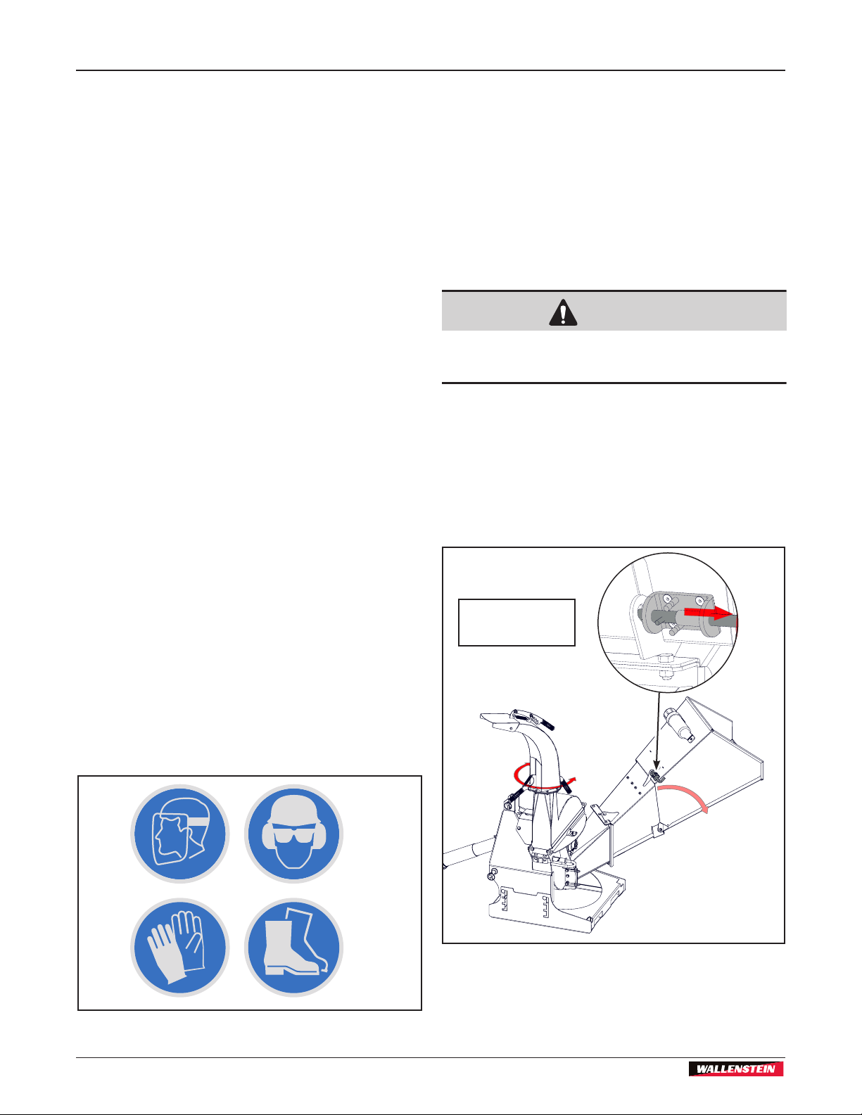
13.2 Stow the Feed Table
(All models except the BX36S.) The feed chute folds
up when not in use for transportation and storage.
1. Release the feed chute lock pin.
2. Carefully grasp the front edge of the feed chute
and fold it up to its vertical position.
3. Secure the feed table by engaging the latch pin
into the pin tab.
4. Check that the tractor is in safe working order.
5. Plan your route, choose the most direct and safest
path.
6. Turn the discharge hood and point toward the
tractor to reduce the width of the machine.
7. Secure chipper components including:
• access covers, and shields: bolted
• rotor housing: bolted
• stow the feed table: secure lock pin
NOTE:
When lowering the feed hopper, be aware
of the pinch point between the hopper and
the sub chute.
Z94242
Feed Chute Lock
Pin
Fig. 20 – Feed hopper in stowed position
31

Storage
14. Storage
BX36S
3PH Self-feed Chipper
STORAGE SAFETY
• Store the unit in an area away from human
activity.
• Do not permit children to play on or around
the stored machine
After the season's use or when the machine is not
going to be used for a period of time, place the chipper
in storage.
• Completely inspect all major systems.
• Replace or repair any worn or damaged
components to prevent any unnecessary down
time at the beginning of the next season.
14.1 Placing Chipper in Storage
1. Power Pack Accessory: review the engine owners
manual concerning storage and prepare the engine
for storage.
2. Remove all material from the machine.
3. Thoroughly wash the machine with a pressure
washer or water hose to remove all dirt, mud or
debris.
4. Inspect all rotating parts for entangled material.
Remove all entangled material.
5. Run the machine a few minutes to dry the moisture
from inside the machine.
6. Move the feed hopper up and lock.
• Store the unit in a dry, level area. Support the
frame with planks if required.
NOTE:
When lowering the feed hopper, be aware
of the pinch point between the hopper and
the sub chute.
Z94242
14.2 Removing from Storage
When removing this machine from storage, follow this
procedure:
1. Remove the tarpaulin if covered.
2. Review and follow the Pre-operation Checklist.
(See page 28).
Chute Turned
Inward
Feed Hopper
Stored
7. Turn chute inward.
8. Touch up all paint nicks and scratches to prevent
rusting.
9. It is best to store the machine inside. If that is not
possible, cover with a waterproof tarpaulin and tie
down securely.
10. Store in an area away from human activity.
11. Do not allow children to play around the stored
unit.
Fig. 21 – Feed hopper stored
32

BX36S
3PH Self-feed Chipper
15. Service and Maintenance
MAINTENANCE SAFETY
Service and Maintenance
• Good maintenance is your responsibility.
Poor maintenance is an invitation to trouble.
• Place the machine in the Safe Condition
before performing any service procedure. See
Safe Condition on page 9).
• Follow good shop practices.
- Keep service area clean and dry.
- Be sure electrical outlets and tools are
properly grounded.
- Use adequate light for the job at hand.
• Make sure there is plenty of ventilation. Never
operate the engine of the towing vehicle in
a closed building. The exhaust fumes may
cause asphyxiation.
• Never work under equipment unless it is
blocked securely.
• Always use personal protection devices
such as eye, hand and hearing protectors,
when performing any service or maintenance
work. Use heavy gloves when handling sharp
components.
• Where replacement parts are necessary
for periodic maintenance and servicing,
genuine factory replacement parts must be
used to restore your equipment to original
specications. The manufacturer will not
be responsible for injuries or damages
caused by use of unapproved parts and/or
accessories.
• A re extinguisher and rst aid kit should
be kept readily accessible while performing
maintenance on this equipment.
• Periodically tighten all bolts, nuts and
screws and check that all electrical and fuel
connections are properly secured.
• When completing a maintenance or service
procedure, make sure all safety shields and
devices are installed before placing unit in
service.
15.1 Service
By following a careful service and maintenance
program for your machine, you will enjoy many years
or trouble-free operation.
15.1.1 Fluids and Lubricants
Grease:
Use an SAE multipurpose, high-temperature grease
with extreme pressure (EP) performance. Also
acceptable is an SAE multipurpose lithium base
grease.
Storing Lubricants:
Your machine can operate at top efciency only if clean
lubricants are used. Use clean containers to handle all
lubricants. Store them in an area protected from dust
moisture and other contaminants.
15.2 Greasing
1. Use a hand-held grease gun for all greasing.
2. Wipe grease tting with a clean cloth before
greasing, to avoid injecting dirt and grit.
3. Replace and repair broken ttings immediately.
4. If ttings will not take grease, remove and clean
thoroughly. Also clean lubricant passageway.
Replace ttings if necessary.
15.2.1 Servicing Intervals
See 15.3 Maintenance Schedule on page 38 for
service interval information. The period recommended
is based on normal operating conditions. Severe
or unusual conditions may require more frequent
lubrication
33

Service and Maintenance
BX36S
3PH Self-feed Chipper
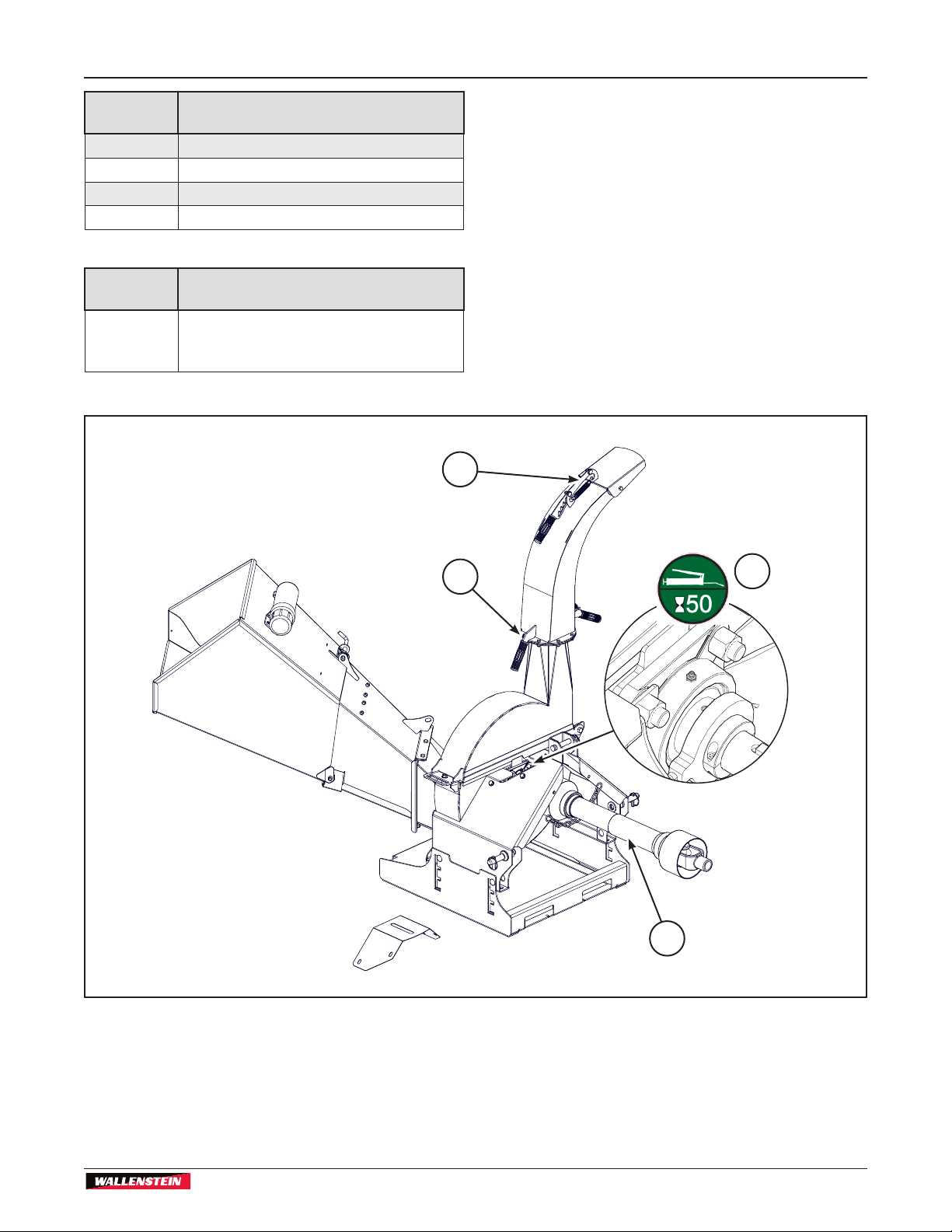
15.2.2 BX36S Grease Points
IMPORTANT! Do Not over grease.
Look for this decal on your machine.
It indicates a grease point and the
interval in hours.
WARNING!
Machine shown with guards removed for
illustrative purposes only. Never operate
machine with guards removed.
1
1 1 1
W001
Refer to Maintenance Schedule on page 38..
IMPORTANT! Grease machine at period shown
or hour interval, whichever comes rst.
Location Every 8 hours or daily
1 PTO lubrication points. See 15.4
Driveline Maintenance on page 40.
Location Every 50 hours or annually
2 Rotor Main shaft, rear roller ange*
3 Rotor cover hinge (2 sides)
* One pump from a hand-held grease gun.
2
3
Fig. 22 – BX36S Grease Points
34

BX36S
3PH Self-feed Chipper
Service and Maintenance
Location Every 50 hours or annually
4 Rotor main shaft, front roller ange*
5 Hood deector
6 Discharge chute swivel
7 PTO telescoping section
* One pump from a hand-held grease gun.
Location Every 100 hours or annually
Wash and clean wood chipper. Remove
entangled material, wood chips, small
debris.
6
5
4
Fig. 23 – BX36S Grease Points
35
7

Service and Maintenance
BX36S
3PH Self-feed Chipper
15.2.3 BX52S, BX72S, BX102S Grease
Points
Look for this decal on your machine.
It indicates a grease point and the
interval in hours.
WARNING!
Machine shown with guards removed for
illustrative purposes only. Never operate
machine with guards removed.
Refer to Maintenance Schedule on page 38..
1
1 1 1
W001
IMPORTANT! Grease machine at period shown
or hour interval, whichever comes rst.
Location Every 8 hours or daily
1 PTO lubrication points. See 15.4
Driveline Maintenance on page 40.
Location Every 50 hours or annually
2 Rotor Main shaft, rear roller ange*
3 Feed Hopper Hinges
4 Rotor cover hinge (2 sides)
* One pump from a hand-held grease gun.
3
2
4
Fig. 24 – BX52S, BX72S, BX102S Grease Points
36
BX36S
3PH Self-feed Chipper
Location Every 50 hours or annually
5 Rotor main shaft, front roller ange*
6 Hood deector
7 Discharge chute swivel
8 PTO telescoping section
* One pump from a hand-held grease gun.
Location Every 100 hours or annually
Wash and clean wood chipper. Remove
entangled material, wood chips, small
debris.
Service and Maintenance
6
7
Fig. 25 – BX52S, BX72S, BX102S Grease Points
5
8
37

Service and Maintenance
15.3 Maintenance Schedule
See Lubrication and Maintenance sections for details
of service.
Maintenance schedule
BX36S
3PH Self-feed Chipper
Perform at time shown or hour interval, whichever
comes rst.
Item
Check twig breaker, rotor blades, ledger blade.
Check that all fasteners are secure.
Lubricate hinges and pivot points.
Lubricate all grease points. See service illustrations.
Adjust rotor and ledger blades.
Clean machine.
Wash and clean wood chipper. Remove entangled
material, wood chips, and small debris.
Every 8 hours
or Daily
Every 50 hours
or Annually
Every 100
hours or
Annually
38

BX36S
3PH Self-feed Chipper
15.3.1 Service Illustration
This illustration shows the general location of service
points for all models in this manual.
Check all nuts, bolts and screws and ensure they are
all properly secured on a regular basis.
Rotor blades: check every 8 hours. Blades
may need to be changed after 8–10 hours,
depending on material being chipped. Test
sharpness every 50 hours
Service and Maintenance
Twig Breaker: check every
8 hours (all except BX36S)
Ledger blade: check every
8 hours. Test sharpness
every 50 hours
Fig. 26 – Service Illustration
39

Service and Maintenance
BX36S
3PH Self-feed Chipper
15.4 Driveline Maintenance
The PTO drive line is designed to telescope to allow for
dimensional changes as the machine goes through its
operational range.
A heavy duty plastic tubular guard encloses the driving
components and is designed to turn relative to the
driving components.
The drive line should telescope easily and the
guard turn freely on the shaft at all times. Annual
disassembly, cleaning and lubrication is recommended
to insure that all components function as intended.
Ensure that the universal joints are lubricated, inspect
and lubricate every 8 hours.
When reassembling the driveline, ensure that
the driveline is assembled "in phase", to avoid
unnecessary vibration when the machine is running.
15.5 Shear Pin
The PTO drive line is designed with a shear pin at the
input yoke to prevent overloading the drive system.
Remove the broken parts from the yoke when the pin
shears and replace with genuine Wallenstein parts.
The drive system is designed to function well without
failing the shear pin. If it does fail, generally it is
being fed too fast or something very hard has been
jammed into the rotor or between the blades. Always
unplug the system and determine the cause of the
problem and correct it before resuming work. Shear pin
replacements are available from your dealer
Plastic Guard
Guard Lubrication
Points
U-joint Lubrication
point
Telescoping
Shaft
Fig. 27 – Driveline Maintenance
40

BX36S
3PH Self-feed Chipper
Service and Maintenance
15.6 Rotor Lock Pin
All models have a rotor lock pin on the upper rotor
housing. It works on a pull, twist and release principle
and is a simple and reliable spring pin used to secure
the rotor from moving while the upper rotor housing
is open. It is designed to only be able to be engaged
when the rotor housing is open, the spring pin cannot
be engaged when the rotor housing is closed. This
feature prevents unintended use while in operation.
The rotor lock pin should be used anytime the rotor
housing is open to prevent potential injury.
Rotor Hood
Open
Lock Pin
Engaged
15.7 Twig Breaker
(All Models except BX36S.)
The Twig Breaker is a breaker tab located on side of
the lower rotor housing. The discharge paddle passes
around the twig breaker and helps to break the material
into smaller pieces and turn it into mulch. Inspect the
twig breaker for damage such as gouges, a bent, or
missing tooth.
A damaged or worn twig breaker should be replaced.
Twig Breaker
Bolts
Twig Breaker
Fig. 28 – Rotor Lock Pin (BX52S, BX72S, BX102S shown)
Twig Breaker
Nuts
Lower Rotor
Housing
Fig. 29 – Twig Breaker
41

Service and Maintenance
BX36S
3PH Self-feed Chipper
15.8 Rotor Blades
The rotor and ledger blades need to be sharp for the
chipper to perform as expected. Periodic inspection is
recommended. Keep the blades sharp to reduce the
amount of power required during operation. Watch
the sharpness of the blades when processing material
with a lot of sand, soil or dirt mixed with it. Reverse or
sharpen the blades if the cutting edge becomes dull.
The rotor is equipped with 4 blades spaced evenly to
keep the rotor in balance. If one blade needs to be
changed, the one opposite should also be changed.
It is recommended that the rotor blades be removed
from the rotor when sharpening. Always sharpen the
blades at a 45° angle to provide the best cutting effect
as it meets the stationary blade. Be sure to tighten the
blade mounting bolts to their specied torque when
re-installing the blades to the rotor.
CAUTION!
Avoid getting pinched or wedged between the lower
rotor housing and rotor. The rotor is very heavy.
Turn rotor slowly and be aware of hand positioning.
W002
7. Tighten bolts as specied in the torque chart.
8. Repeat steps for remaining blades.
Rotor Blade
Bolts
Rotor
Rotor Lock
Leading Edge
WARNING!
Machine shown with guards removed for
illustrative purposes only. Never operate
machine with guards removed.
15.8.1 Changing Rotor Blades
Place machine in Safe Condition. (See page 9.)
1. Remove the bolt that secures the upper rotor
housing, and carefully open the rotor housing.
2. With care, slowly rotate chipper rotor plate until the
rotor lock lines up with lock hole in the rotor plate.
3. Engage the rotor lock, and ensure it snaps into the
lock hole. Do not allow the rotor lock to snap into
the chipper blade slot, damage to the blade may
result.
4. Remove the bolts that hold the rotor blade to the
rotor, remove the blade.
5. Rotate the blade and reinstall or replace with new
or re-sharpened blade.
W001
Fig. 30 – Proper orientation of rotor blade
NOTE:
The rotor blade may have 4 mounting
holes, depending on the model. The
removal / replacement procedure is the
same.
6. Ensure the blade is properly oriented, with the
leading edge out. The blade is designed to t into
the rotor one way only. See diagram for proper
installation.
42

BX36S
3PH Self-feed Chipper
Service and Maintenance
15.9 Ledger Blades
Ledger blades shear material as it passes the moving
rotor blades.
Ledger blades are located on the lower rotor housing,
mounted on slotted holes for adjustment. There are
four usable corners on the blade. When the corner
facing the rotor blade rounds over, remove the blade
and re-install so a different corner is facing the rotor
blade.
Place machine in Safe Condition (See page 9).
NOTE:
8. Tighten adjuster nuts, then tighten ledger blade
bolts. Tighten as specied in the torque chart.
Ledger Blade
For fast and easy setting, use the chipper
clearance setting gauge, included with
your BX chipper.
Bolts
Ledger Blade
Bolts
Ledger Blade
Fig. 31 – Cut away view to show ledger blade assembly
1. Remove the four bolts that hold the ledger blade to
the ledger mount.
2. Carefully remove the blade, pull it down and
slightly to the side to clear the axle.
3. Rotate the blade and reinstall, or replace with new
or re-sharpened blade.
4. Hand tighten the bolts.
5. Set the clearance between the ledger and rotor
blades using the ledger adjuster.
6. Loosen the nuts on the adjuster and move the
ledger to the correct clearance at 1/32–1/16"
(.76–1.52 mm) to obtain the best performance.
Ledger Blade
Fig. 32 – Cut away view to show ledger blade assembly
NOTE:
The ledger blade may have three
mounting holes, depending on the model.
The removal / replacement / adjustment
procedure is the same for both.
7. Make sure both adjusters are moved evenly.
43

Service and Maintenance
BX36S
3PH Self-feed Chipper
15.9.1 Ledger Knife Spacer Tool
The Ledger Knife Spacer Tool is located on the lower
rotor housing.
As the blade wears, it can be rotated or ipped to use
a fresh corner. If the blade is moved, it must have its
clearance settings adjusted to maintain its shearing
efciency.
The best way to ensure you have the correct clearance
is to use the Wallenstein Ledger Adjusting Tool. It is the
correct thickness to set the recommended clearance
between the rotor and stationary blades.
IMPORTANT! The clearance should be set
to 1/32–1/16" (.76–1.52 mm) for optimum
performance.
Depending on the chipper model, there may or may not
be adjusting bolts along with mounting nuts and bolts
to secure the ledger blade. Adjusting the ledger blade
is the same in either case.
Place machine in Safe Condition (See page 9).
1. Remove the bolt that secures the upper rotor
housing, and carefully open the rotor housing.
5. Move the ledger blade in towards the rotor blade.
6. Ensure you move the ledger evenly, so the entire
edge of the ledger is in contact with the gauge.
7. Hand tighten the fasteners, the gauge should drag
slightly between the blades
8. With the gauge in place:
• Tighten adjuster nuts rst (if equipped).
• Tighten ledger blade bolts.
• Tighten all fasteners as specied in the torque
chart.
9. Check that the gauge still drags slightly when you
remove it.
Ledger blade is now correctly adjusted and is ready for
service.
It is recommended to occasionally check the blade
clearance per your chippers maintenance schedule.
NOTE:
Depending on the model, the ledger blade
may have 3 or 4 mounting holes. The
adjustment procedure is the same for
both.
2. Carefully move the rotor so the a rotor blade
overlaps the ledger blade.
3. Loosen the fasteners and / or adjusters and move
the ledger away from the rotor blade.
4. Insert the gauge between the ledger blade and
rotor blade
Adjuster
Gauge
Ledger Blade
Cut-Away View Showing
Ledger Blade
Rotor Blade
Rotor
Fig. 33 – Ledger Blade Adjusting Tool
44
Ledger Knife
Spacer Tool

BX36S
3PH Self-feed Chipper
Trouble Shooting
16. Trouble Shooting
The Wallenstein 3-Point Hitch Wood Chipper is
designed with blades on a rotor to cut, shear and chip
wooden material. It is a simple and reliable system that
requires minimal maintenance.
The following table lists causes and solutions to
problems that could be encountered.
Problem Cause Solution
Obstructed discharge.
Rotor does not turn
Slow feeding.
Unusual vibration while
operating.
Machine requires
excessive power or stalls.
Rotor plugged.
Broken shear pin Ensure machine is off
Low engine speed
Blades and/or knives are
dull.
Rotor blade angle wrong,
improper angle.
Obstructed discharge.
Broken or missing blade .
PTO driveline out of
phase
Rotor may be bent
Obstructed discharge.
Feeding in too much
material
Feeding material too
quickly
Rotor plugged.
Green material will
not discharge.
Chipper blade clearance
too large.
Dull blades.
If a problem encountered that is difcult to solve,
contact a Wallenstein distributor or dealer. Have the
chipper serial number handy.
Always wear Personal Protective Equipment (PPE)
whenever operating the Wood Chipper or working in
the vicinity.
Caution
Clear debris from
discharge chute.
Inspect and clear chipper
hopper lower rotor
housing and rotor.
Set throttle to speci ed
speed (540–1000 rpm)
Rotate, sharpen or
replace blade and/or
knives.
Re-sharpen knives to
speci ed angle and check
that blade is installed
properly.
Clear debris from
discharge chute .
Replace broken / missing
blade.
Align driveline Ensure machine is off.
Check rotor to see if it
wobbles.
Replace rotor
Clear debris from
discharge chute
Feed smaller amounts into
chipper hopper.
Feed larger material
slowly into chipper hopper.
Inspect and clear chipper
hopper lower rotor
housing and rotor.
Allow material to dry or
alternate dry/wet material.
Set clearance to 1/32–
1/16" (.76–1.52 mm). Use
chipper clearance tool
(see accessories)
Rotate, sharpen or
replace blade
Ensure machine is off
Ensure machine is off
Ensure machine is off
Ensure machine is off
Ensure machine is off
Ensure machine is off.
Ensure machine is off.
Call technician for repair
Ensure machine is off
Ensure machine is off
Ensure machine is off
Ensure machine is off
45

Specications
17. Specications
Model BX36S BX52S BX72S BX102S
Drive System
Power
Requirements for
Maximum Capacity
HP Range
Chipper Capacity
(diameter)
Chipper Housing
Opening
Rotor Size
Number of Rotor
Knives
Knife Type
Rotor Weight
Feeding System
PTO height
(from ground)
Mounting System
Weight
Dimensions
(L x W x H)
Discharge Hood
Rotation
Discharge Hood
Height
Rated Speed
PTO with shear bolt
9 cm x 23 cm
4 segmented knives 4 segmented knives 4 full knives 4 segmented knives
4-bolt hardened / reversible 4-bolt hardened / reversible 4-bolt hardened / reversible 3-bolt hardened / reversible
13.44"–19.0" (adjustable)
34.13–42.26 cm
3-Point Hitch Cat I
(iMatch™ and quick hitch
55" x 45" x 60"
140 cm x 114 cm x 152 cm
540–1000 rpm 540–1000 rpm 540–1000 rpm 540–1000 rpm
3PH Self-feed Chipper
Direct Drive,
25–30 hp
19–22 kW
12–30 hp
9–22 kW
3.5"
9 cm
3.5" x 9"
25"
63.5 cm
96 lb
43.5 kg
Manual Feed Manual Feed Manual Feed Manual Feed
compatible)
395 lb
179 kg
270° 270° 270° 270°
60"
152 cm
Direct Drive,
PTO with shear bolt
40–45 hp
30–34 kW
18-50 hp
14-37 kW
5"
13 cm
5" x 10"
13 cm x 26 cm
25"
63.5 cm
125 lb
56.7 kg
13.44"–19.0" (adjustable)
34.13–42.26 cm
3-Point Hitch Cat I
(iMatch™ and quick hitch
compatible)
505 lb
229 kg
43” x 55” x 66”
110 cm x 140 cm x 168 cm
66"
168 cm
Direct Drive,
PTO with shear bolt
65–75 hp
26–56 kW
35-100 hp
26-75 kW
7"
17 cm
7" x 12"
17 cm x 30 cm
28"
71 cm
175 lb
79.3 kg
19.0"
42.26 cm
3-Point Hitch Cat I
(iMatch™ and quick hitch
compatible)
728 lb (estimated)
330.2 kg
64" x 70" x 82"
163 cm x 178 cm x 208 cm
82"
208 cm
Direct Drive,
PTO with shear bolt
90–120 hp
67–90 kW
65-150 hp
49-112 kW
10"
25 cm
10" x 15"
25 cm x 38 cm
36"
91 cm
400 lb
181.4 kg
23.0"
58.42 cm
3-Point Hitch Cat II
(iMatch™ and quick hitch
compatible)
1143 lb (estimated)
518.5 kg
71" x 71" x 89"
180 cm x 180 cm x 226 cm
89"
226 cm
BX36S
46

BX36S
3PH Self-feed Chipper
Model BX36S BX52S BX72S BX102S
Standard Features
• Aggressive Self Feed
System
• Multi Position, Locking
Discharge Chute
• Reversible Rotor
Blades
• Reversible Ledger Knife
• Manual Feed Hopper
• Ledger Knife Spacer
Tool
• Bearing Protection
Plates
• Four-position Rotor
Lock
• Adjustable Ski Base
• Single Blade Twig
Breaker
• 270° Single Handle Exit
Chute Rotation
• Dual Knob Easy
Change Discharge
Deector
• Three-position Select
3-PH Lift Arm Width
• Aggressive Self Feed
System
• Multi Position, Locking
Discharge Chute
• No Tools Fold Up Feed
Hopper with latch
• Reversible Rotor
Blades
• Reversible Ledger Knife
• Manual Feed Hopper
• Ledger Knife Spacer
Tool
• Bearing Protection
Plates
• Positive Adjust Ledger
Knife
• Four-position Rotor
Lock
• Adjustable Ski Base
• Dual Blade Twig
Breaker
• 270° Dual Handle Exit
Chute Rotation
• Single Handle Easy
Change Discharge
Deector
• Three Position Select
3-PH Lift Arm Width
• Aggressive Self Feed
System
• Multi Position, Locking
Discharge Chute
• No Tools Fold Up Feed
Hopper with latch
• Reversible Rotor
Blades
• Reversible Ledger Knife
• Manual Feed Hopper
• Ledger Knife Spacer
Tool
• Bearing Protection
Plates
• Positive Adjust Ledger
Knife
• Four-position Rotor
Lock
• Dual Blade Twig
Breaker
• 270° Dual Handle Exit
Chute Rotation
• Single Handle Easy
Change Discharge
Deector
• Three Position Select
3-PH Lift Arm Width
Specications
• Aggressive Self Feed
System
• Multi Position, Locking
Discharge Chute
• No Tools Fold Up Feed
Hopper with latch
• Reversible Rotor
Blades
• Reversible Ledger Knife
• Manual Feed Hopper
• Ledger Knife Spacer
Tool
• Bearing Protection
Plates
• Positive Adjust Ledger
Knife
• Four-position Rotor
Lock
• Dual Blade Twig
Breaker
• 270° Dual Handle Exit
Chute Rotation
• Single Handle Easy
Change Discharge
Deector
• Three Position Select
3-PH Lift Arm Width
47

Specications
17.1 Bolt torque
BX36S
3PH Self-feed Chipper
Checking Bolt Torque
The tables shown give correct torque values for
various bolts and capscrews. Tighten all bolts to
the torque values specied in the table, unless
indicated otherwise. Check tightness of bolts
periodically.
IMPORTANT! If replacing hardware, use
fasteners of the same grade.
IMPORTANT! Torque gures indicated in the
table are for non-greased or non-oiled threads.
Do not grease or oil threads unless indicated
otherwise. When using a thread locker,
increase torque values by 5%.
NOTE:
Bolt grades are identied by their
head markings.
Imperial Bolt Torque Speci cations
Bolt
Diameter
1/4" 6 8 9 12 12 17
5/16" 10 13 19 25 27 36
3/8" 20 27 33 45 45 63
7/16" 30 41 53 72 75 100
1/2" 45 61 80 11 0 115 155
9/16" 60 95 115 155 165 220
5/8" 95 128 160 215 220 305
3/4" 165 225 290 390 400 540
7/8" 170 230 420 570 650 880
1" 225 345 630 850 970 1320
SAE Gr. 2 SAE Gr. 5 SAE Gr. 8
lbf•ft N•m lbf•ft N•m lbf•ft N•m
Torque Value
Metric Bolt Torque Speci cations
Bolt
Diameter
M3 0.4 0.5 1.3 1.8
M4 2.2 3 3.3 4.5
M6 7 10 11 15
M8 18 25 26 35
M10 37 50 52 70
M12 66 90 92 125
M16 166 225 229 310
M20 321 435 450 610
M30 1,103 1 495 1,550 2 100
M36 1,917 2 600 2,700 3 675
Gr. 8.8 Gr. 10.9
lbf•ft N•m lbf•ft N•m
Torque Value
48

18. Index
A
ASABE .......................................................................13
Attaching Chipper to Tractor ......................................22
Procedure ..............................................................22
B
Bolt torque ..................................................................48
Bottom Rotor Housing ................................................19
C
Capacity .....................................................................29
Category I & II ............................................................22
Changing Rotor Blades ..............................................42
Checking Bolt Torque .................................................48
Chipper Plugged ........................................................30
Chipper Severely Plugged .........................................30
Controls ......................................................................24
Hood Deector ......................................................25
D
Deector .............................................................. 19, 20
Delivery Inspection Report ...........................................6
Discharge ............................................................ 19, 20
Discharge Chute .......................................... 19, 20, 24
Discharge Latch Handle .............................................19
Driveline Maintenance ................................................40
E
Emergency .................................................................29
Equipment Safety Guidelines ..................................... 11
F
Familiarization ............................................................18
Machine Components ...........................................19
Models BX36S.......................................................... 19
Models BX52S, BX72S and BX102S ....................... 20
Operator Orientation..............................................18
To the New Operator or Owner .............................18
Feed Hopper
Latch ..........................................................................20
Feed Hopper Lock Pin ...............................................26
Fire Extinguisher ........................................................12
rst aid kit ...................................................................12
Folding Feed Hopper .................................................20
G
Grease .......................................................................33
Grease Points .....................................................34, 36
H
Hood Deector ...........................................................25
How to Install Safety Signs ........................................18
I
Informative Labels ........................................................4
L
Label Information .........................................................4
Ledger .......................................................... 20, 43, 44
Ledger Knife Spacer Tool ....................................20, 44
Lower Link .................................................... 19, 20, 23
M
Machine Break-In .......................................................28
Machine Components ................................................19
Machine Set-up ..........................................................26
Maintenance Labels .....................................................4
Maintenance Safety ...................................................12
Maintenance Schedule ...............................................38
O
Operating Hints ..........................................................30
Operating safety ........................................... 31, 32, 33
Operating Safety ........................................................10
Operation ...................................................................26
Adjust Ski Height ...................................................27
Be Prepared ..........................................................26
Chipper Plugged....................................................30
Chipper Severely Plugged ....................................30
Chipping Operation ...............................................29
Machine Break-In ..................................................28
Machine Set-up .....................................................26
Operating Hints .....................................................30
Operating Safety ..................................... 31, 32, 33
Pre-Operation Checklist ........................................28
Starting Procedure ................................................29
Stopping ................................................................29
Stopping in an Emergency ....................................29
Operator Orientation ..................................................18
Operator's Manual Tube .............................................19
OSHA .........................................................................13
P
Personal Protective Equipment (PPE) .........................9
PPE ................................................................ 9, 26, 45
Pre-Operation Checklist .............................................28
Product Labels .............................................................4
PTO Shaft Connection ...............................................21
Determine Correct PTO Shaft Length ...................21
R
Replace Damaged Safety Signs ................................18
Rotor Blade .........................................................19, 20
Rotor Lock ............................................. 19, 20, 41, 42
Rotor Lock Pin ............................................................41
S
Safe Condition .......................................................9, 12
Safety ...........................................................................8

Equipment Safety Guidelines ................................ 11
General....................................................................9
How to Install Safety Signs....................................18
Maintenance Safety...............................................12
Personal Protective Equipment (PPE) ....................9
Safety Alert Symbol ................................................. 8
Safety Do's and Don'ts ............................................9
Safety Training ......................................................12
Signal Words ...........................................................8
Sign-Off Form ........................................................13
Storage Safety.......................................................13
Safety Alert Symbol ...................................................... 8
Safety Do's and Don'ts .................................................9
Safety Notice Labels ....................................................4
Safety Training ...........................................................12
Service and Maintenance ...........................................33
BX36S Grease Points ...........................................34
BX52S, BX72S, BX102S Grease Points ...............36
Driveline Maintenance ...........................................40
Greasing ................................................................33
Servicing Intervals .................................................... 33
Ledger Knife Spacer Tool ......................................44
Maintenance Schedule
Service Illustration .................................................... 39
Rotor Blades..........................................................42
Rotor Lock Pin .......................................................41
Service ..................................................................33
Shear Pin...............................................................40
Twig Breaker .........................................................41
Service Illustration ......................................................39
Servicing Intervals ......................................................33
Shear Pin ...................................................................40
Ski ......................................................... 19, 20, 22, 27
Specications .............................................................46
Bolt torque .............................................................48
Starting Procedure .....................................................29
Stopping .....................................................................29
Stopping in an Emergency .........................................29
Storage .......................................................................32
Placing Chipper in Storage ...................................32
Removing from Storage ........................................32
Storage Safety ...........................................................13
Twig Breaker .......................................................20, 41
U
Upper Rotor Housing ..........................................19, 20
W
Warranty .......................................................................5
T
Top Link ........................................................ 19, 20, 23
Transporting ...............................................................31
Prepare for transport .............................................31
Stow the Feed Table ..............................................31
Trouble Shooting ........................................................45


www.wallensteinequipment.com
 Loading...