

Page 1

INSTALLATION GUIDE
POWER SHARING SMART
EN - V2.0
Page 2

INSTALLATION GUIDE
1. Introduction...............................................................................................................................................................................................
2. Installation.................................................................................................................................................................................................
2.1. Positioning in the System T/NT - Chargers............................................................................................................................................................
2.2 CAN Cabling (CAN-H/-L)...............................................................................................................................................................................................................
3. Configuration...........................................................................................................................................................................................
3.1 Master & Slave setup and powering on........................................................................................................................................................................
3.2 Master Configuration.............................................................................................................................................................................................................................
4. Operation...................................................................................................................................................................................................
4.1 Status Visualisation...................................................................................................................................................................................................................................
5. Troubleshooting.....................................................................................................................................................................................
p. 3
p. 6
p. 7
p. 8
p. 11
p. 12
p. 13
p. 14
p. 15
p. 17
EN - V2.0
Page 3

INSTALLATION GUIDE
EN - V2.0 3
1. INTRODUCTION
Power Sharing Smart
Page 4
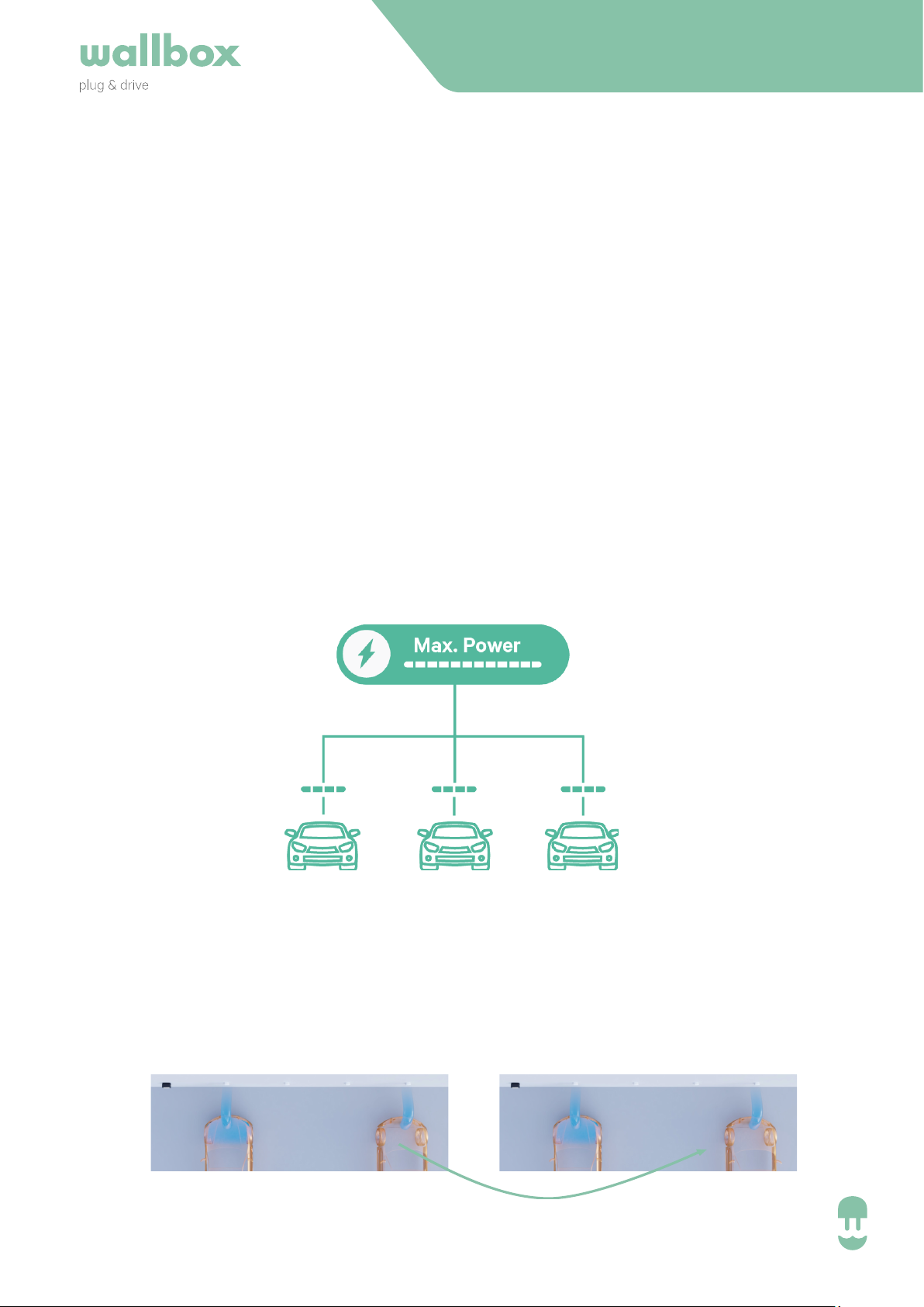
1. Introduction
20 kW 20 kW
15 kW
20 kW
20 kW
25 kW
15 kW
25 kW
What is the biggest problem when installing many chargers?
• Available power is limited (upgrade of installation is very expensive).
How do we solve the problem?
• Most eicient distribution of the available power – without extra cost / additional device.
Which factors did we take into account?
• A car stays longer than it charges – Wallbox will use that available power.
• Each installation has their own characteristics – Wallbox allows a most flexible installation.
• The installation is often not connected to the Internet – Wallbox does not require
Internet-connection.
• When connecting many devices, easy troubleshooting is key – Wallbox gives full visibility
over the status.
INSTALLATION GUIDE
Eiciency
Re-assignation of unused power, example:
• A car uses actually less than it has assigned from power sharing.
• A car is full and will not charge anymore.
EN - V2.0 4
Page 5
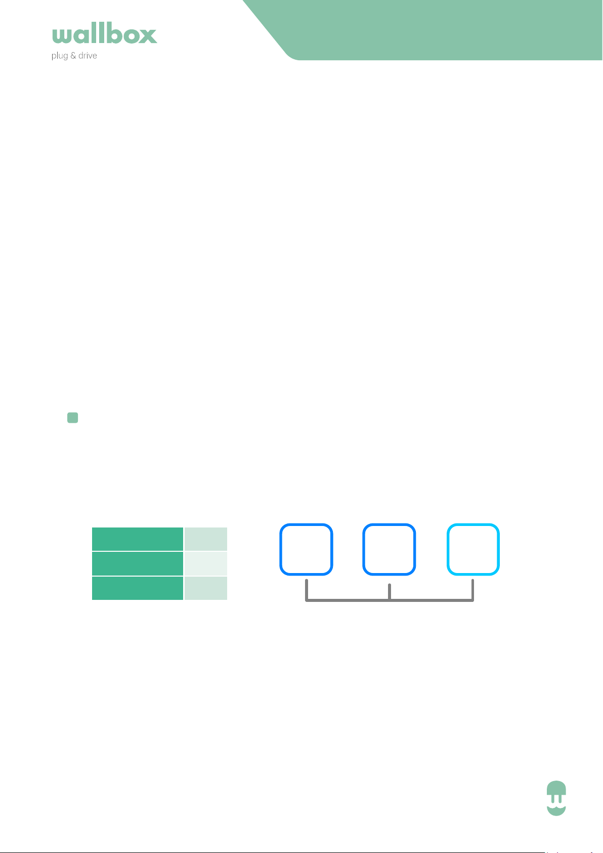
Robustness
No. Chargers 3
Max. Current
12 A
Min. Current 6 A
• If a charger looses connection (due to bad cabling) it can charge with 6 A and Master
will say “missing slaves”
• A newly powered on charger will be added to the system within 1 minute.
Flexibility
INSTALLATION GUIDE
• Connect between 1 and 24 chargers with the Master.
• Any kind of installation .
• Configuration of the system (power/chargers) can be easily changed.
• Up to 250 m distance of communication.
Possibility to install more chargers than can charge at the same time
!
“First-come-first-serve” principle
Example:
Charging
1
In queue
2 3
EN - V2.0 5
Page 6

INSTALLATION GUIDE
2. INSTALLATION
Power Sharing Smart
EN - V2.0 6
Page 7
INSTALLATION GUIDE
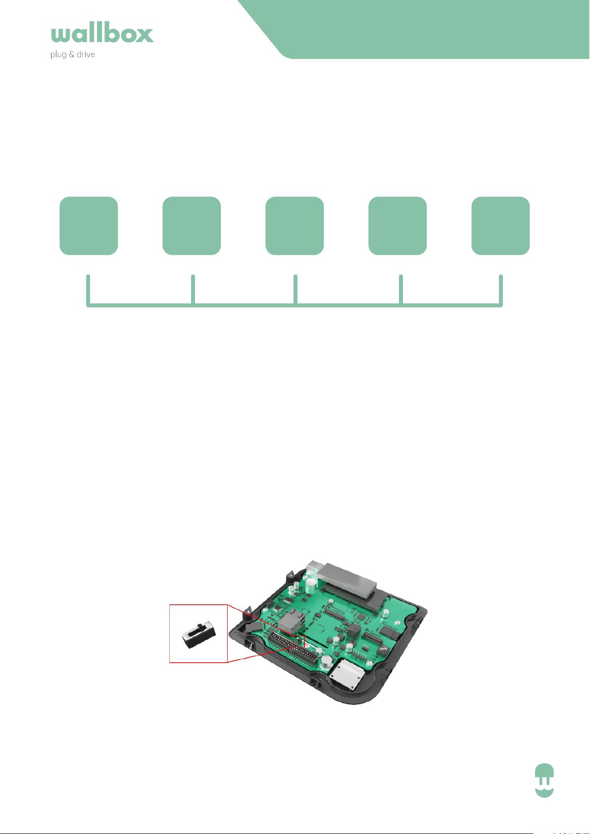
2.1 Positioning in the System (T/NT-Chargers)
T NT NT NT T
When installing the Wallbox in Power Sharing, the location is important to take into account.
The Power Sharing system includes two Terminating (T) chargers and the rest of NonTerminating (NT) chargers as shown in the image.
Each charger includes an electric element (resistor) that defines wether it is T or NT:
• Copper: The way to turn it from NT to T is to change the switch position it has inside.
• Commander or Pulsar: There’s an specific order for connecting Commander or Pulsar,
which is pointed in the proper charger as NT or T.
Once the location is clear, the charging station can be installed according to its delivered
installation manual.
COPPER Terminating/Non-Terminating Switch
EN - V2.0 7
Page 8
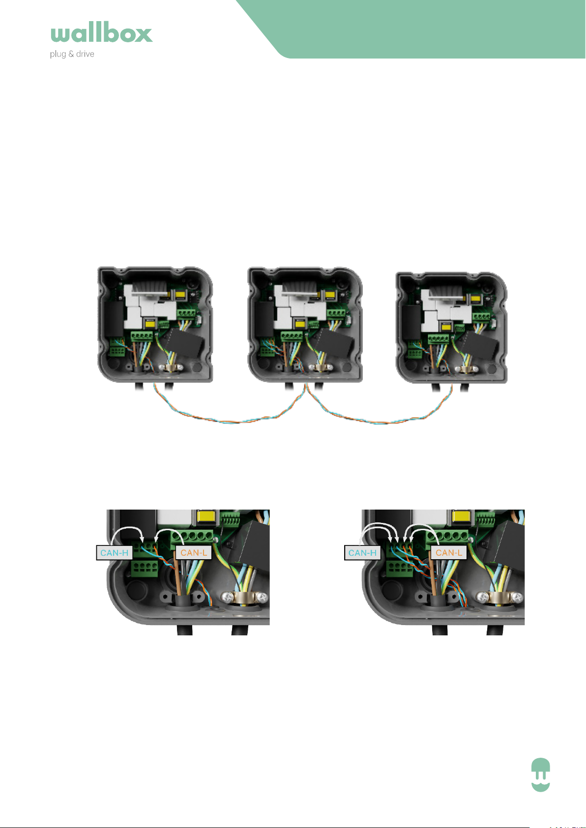
2.2 CAN Cabling (CAN-H/-L)
• The chargers communicate through a cabling system that connects the chargers to the
ones next to it.
• The cabling consists of a CAN-low (CAN-L) and a CAN-high (CAN-H).
• We recommend to use the following cable-type: Ethernet Class 5E no shield, 1 pair.
• A total maximum length of 250 m can be installed.
2.2.1 Instalation: Cabling (Copper)
T TNT
INSTALLATION GUIDE
Copper has two slots for input and output cabling so the conjunction is done inside the charger.
Copper NT connectionCopper T connection
• CAN-H must be connected to CAN-H
• CAN-L must be connected to CAN-L
EN - V2.0 8
Page 9
INSTALLATION GUIDE
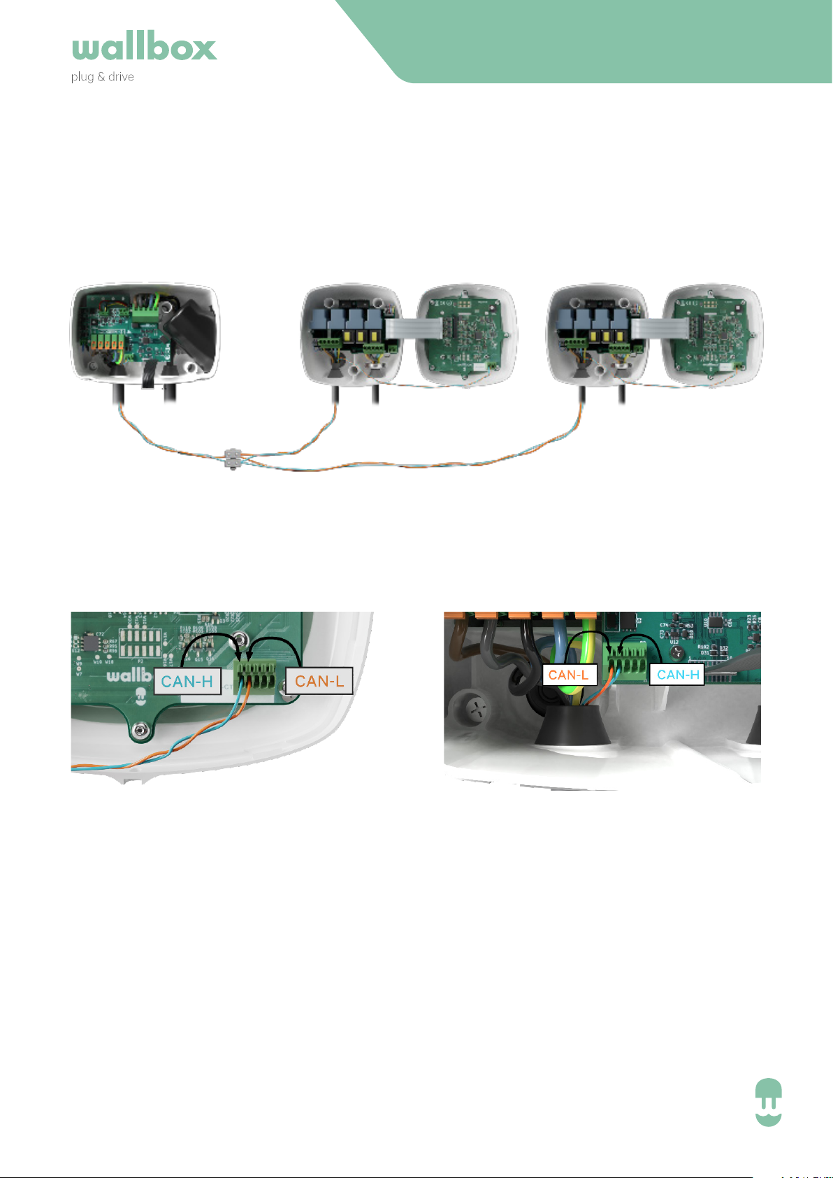
2.4. Instalation: Cabling (Commander/ Pulsar)
Commander and Pulsar only have one slot so the conjunction is done with external terminals.
Pulsar connection Commander connection
• CAN-H must be connected to CAN-H
• CAN-L must be connected to CAN-L
EN - V2.0 10
Page 10

INSTALLATION GUIDE
3. CONFIGURATION
Power Sharing Smart
EN - V2.0 11
Page 11
INSTALLATION GUIDE
Charger Master Slave
Copper X x
Commander X X
Pulsar x
3.1 Master and Slave setup and Powering On
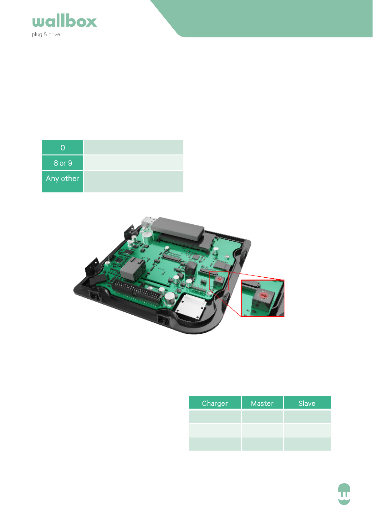
The selection of the rotary switch determines the role in the power sharing system.
0 Slave
8
or 9 Master
Any
other Normal charger
(see installation manual)
The chargers can be configured in the following way:
• Any combinations are possible
• The master can be set at any position within the group (T or NT).
EN - V2.0 12
Page 12
INSTALLATION GUIDE
3.2 Master Configuration
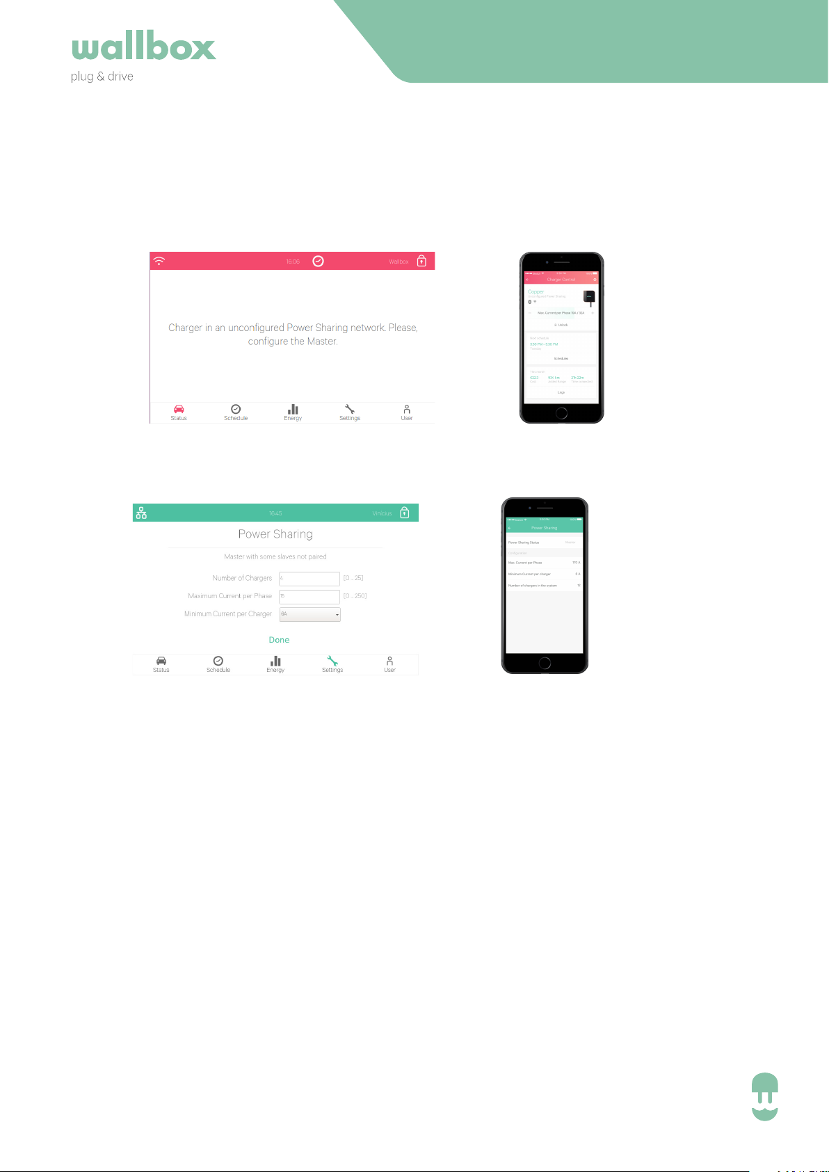
Once the system has been powered on, the charger will visualise the state “unconfigured
master” by a red LED or the dashboard of the charger.
Commander
If you move further to the settings of the Master, the power sharing system can be configured:
Commander
* If the Master is a Copper, you need to have a myWallbox account and connect via Bluetooth
and the App with the charger (see Copper User Guide).
Once connected, select the settings->power sharing to configure the system.
In the Master 3 parameters need to be configured:
• Number of Chargers in the Power Sharing System (to assure that the master knows all
chargers connected).
• This number must include the master charging station
Pulsar / Copper
Pulsar / Copper
• Maximum Current per Phase
• This value determines the maximum that your installation can carry. Typically this
value can be drawn from the main MCB, that has been installed for this power
supply.
• Minimum Current per Charger (6 A or 10 A)
• While the standards define a minimum current of 6 A (default value), some cars
need to have a minimum current of 10 A.
EN - V2.0 13
Page 13

INSTALLATION GUIDE
4. OPERATION
Power Sharing Smart
EN - V2.0 14
Page 14
4.1 Status Visualisation
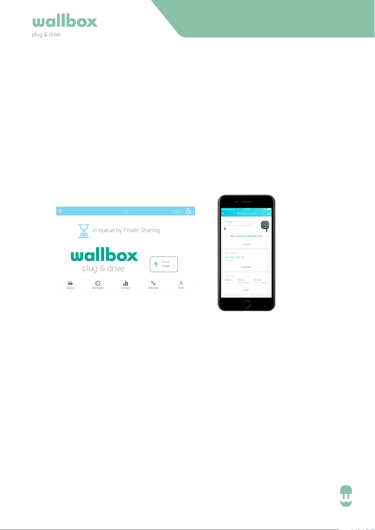
In queue by power sharing: Not enough power available for this charger.
• If the power has already been reduced to the mínimum, the newly plugged cars will go
into this state
• Once the system has enough power available (e.g. a car is full) it will start charging
INSTALLATION GUIDE
Commander
Pulsar / Copper
EN - V2.0 15
Page 15
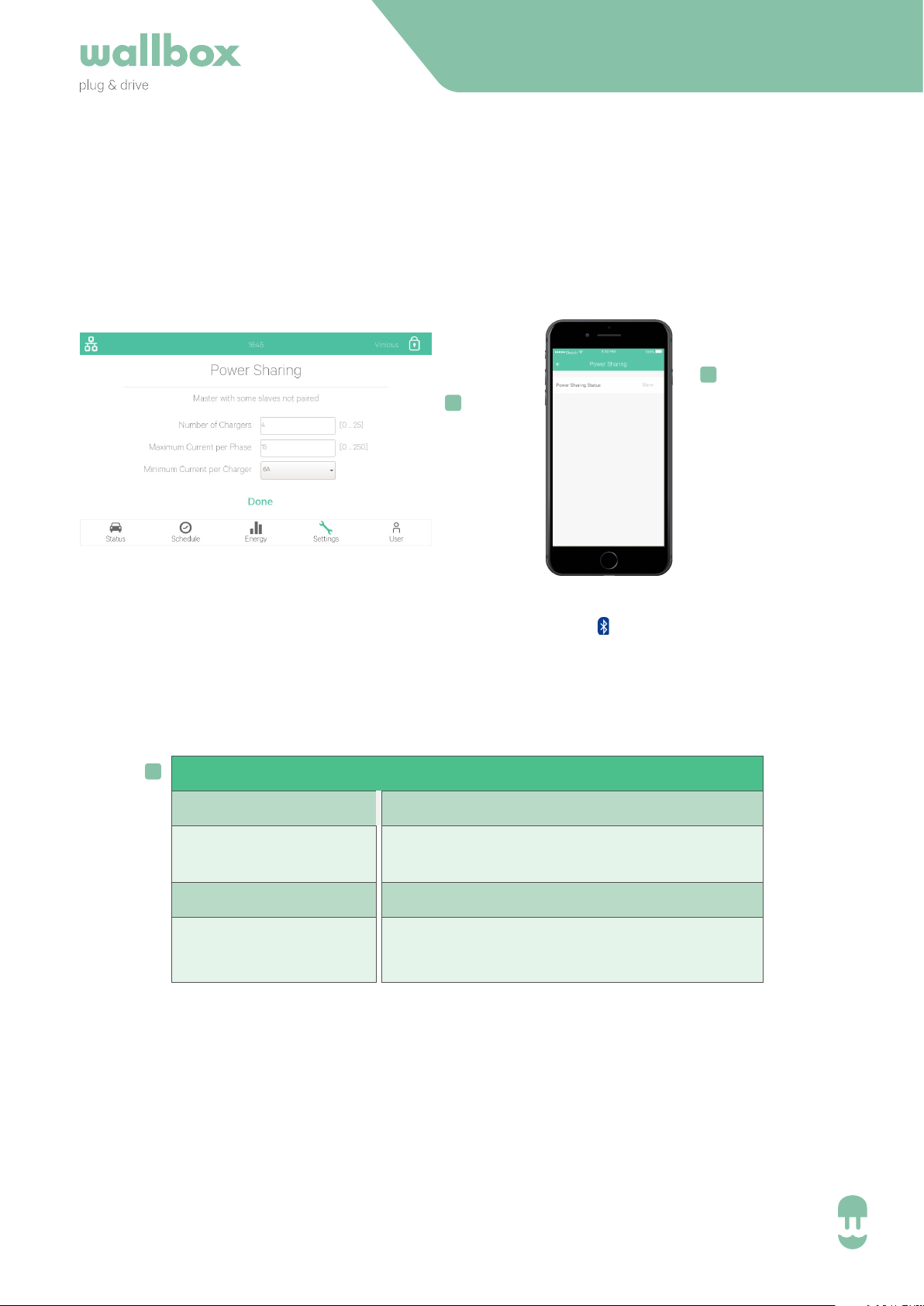
4.1 Status Visualisation
Information about the Power Sharing comunication:
INSTALLATION GUIDE
!
!
Commander
(Settings > System > Power Sharing)
• The master will show the configuration menu.
• The slaves will just show their current status.
!
• Unpaired slave is also visualised as: Pulsar/ Copper visualise with this fast blinking LED.
PS Status
Slave
Unpaired Slave
Master
Master
Uncomplete Net
Description
Succesfully paired slave charger
Slave charger that has not been
paired (can charge with 6A)
Master Charger
Master charger that is detecting less
slaves than have been configured
Pulsar / Copper
(Settings > Power Sharing)
Bluetooth is required.
EN - V2.0 16
Page 16

INSTALLATION GUIDE
5. TROUBLE SHOOTING
EN - V2.0 17
Power Sharing Smart
Page 17

5.1 Troubleshooting
Upgrading from older Power Sharing Versions
As Power Sharing is a functionality that is working across our charging stations, and not only on
a single one, all chargers must work the same.
Therefore, when upgrading from an older version of Power Sharing, you need to update the Software of all of them. Our user guides explain you the update process.
Once the update of all chargers of the system has been performed, follow the chapter 4 of this
manual. After, you are good to go.
Please take into account that the setup of the system (Chapter 1 and 2 of this manual) is kept
identical
INSTALLATION GUIDE
Charger(s) have a red LED/HALO/top screen
• After the start up, this is the default colour on a power sharing net. If it lasts more than
around 30 seconds, then check that the net is configured properly. If not, set the net and
wait from 5 to 30 seconds.
• Make sure that the nº of chargers includes the master.
• Make sure that the maximum current per phase is set properly and that is higher than the
minimum to be assigned.
Charger(s) have a blinking green LED/HALO or on Commander appears
the message “Slave not paired with the power sharing network on the
Power Sharing menu”.
• Poor contact on the CAN cables. Check that all the CAN cables are properly connected on
the chargers.
• Wrong resistor value between CAN lines. Power o all the charger and measure the Ohm
resistor between CAN-H and CAN-L, it mut be around 60 Ohms.
Resistor’s value between CAN lines is dierent than 60 Ohms
• If it is higher is because there’s only one charger with the terminal resistors. If it is lowe is
beacuse there are more than 2 charger with terminal resistors.
• Make sure that the two ends of the line have the “T” switch (if there’s the switch) selected
or that the resistors are on the correspondant chargers.
EN - V2.0 18
Page 18

5. Troubleshooting
Erratic Behaviour
• Poor contact on the CAN cables. Check that all the CAN cables are properly connected on
the chargers.
• Wrong configuration on the master.
• Wrong resistor value between CAN lines. Power o all the charger and measure the Ohm
resistor between CAN-H and CAN-L, it mut be around 60 Ohms.
Charger keeps waiting for current eventhough there’s no other car
• The current assignation may last up to 30 seconds.
• Make sure that there are no schedules programmed.
INSTALLATION GUIDE
EN - V2.0 19
Page 19

POWER SHARING x.x
Revision info
 Loading...