

wallas SafeFlame 96 D, SafeFlame 97 D User Manual
SafeFlame 96 D / 97 D
1
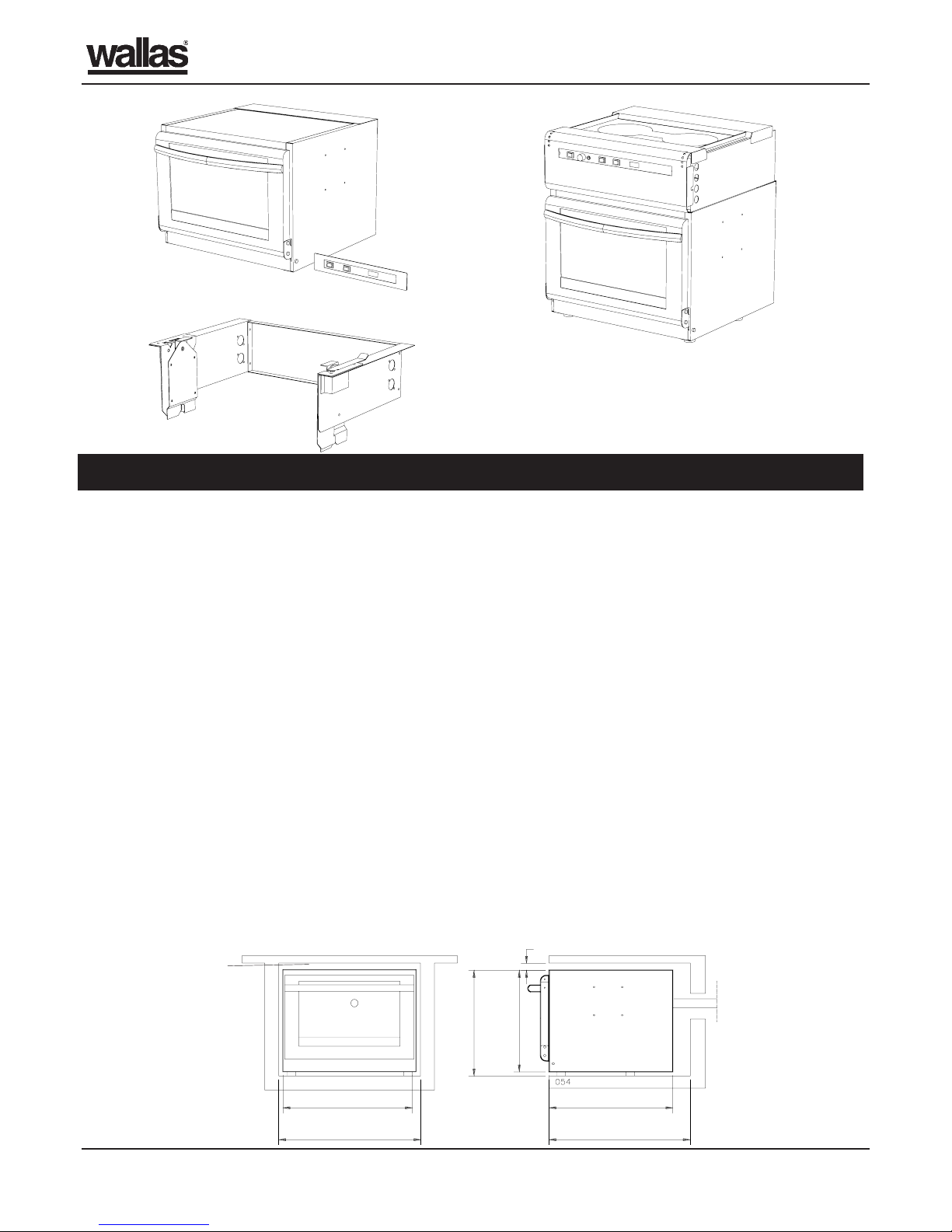
Figure 1: Wallas SafeFlame 96 D Diesel Oven
INSTALLATION INSTRUCTIONS
Figure 4: Minimum dimensions of the space required for installation. If the oven is mounted in a closed space or covered
by a board, the cooling air opening must be reserved above the oven for air circulation, minimum 100 cm2.
Space Requirements
- The dimensions of the space required for installation
are illustrated in figures 4 and 5.
- Drilling cooling air holes in the bottom of the
installation opening is recommended. Collective area
of the holes should be about 30 cm2.
- The dimensions of the space required for installation
of the 96 D oven’s control panel are illustrated in
figure 6.
- The gimbal-mounting frame defines the amount of
space required for a gimbal-mounted appliance.
- T o remove the burner unit for service, the oven has to
be removed from its position.
- The installation opening must be manufactured from
a fire-resistant material or be lined with a fire-resistant
material.
- Note that the control panel cable for the basic 96 D
is 1.5 m long.
Fuel hoses
- The maximum length of the fuel hose is 8 m; the
standard fuel hose is 4 m.
Considerations on the installation place and on its effect on the installation
Figure 2: Wallas SafeFlame 97 D Diesel Stove
Figure 3: Optional gimbal-mounting 113 for both the oven
and stove
A 4-metre long electric cable and a 4-metre long fuel
pipe with a cork and an internal filter are delivered as
standard.
- The recommended position for the fuel tank is 0.5 –
1 m below the oven.
Exhaust pipes
- The maximum length of the exhaust pipe is 4 m.
Exhaust pipe must be insulated with ø 45 mm
insulation pipe.
- The Combination lead-through may be installed into
the hull or deck.
- The hull lead-through should be situated as far aft as
possible, preferably in the stern.
- If it is possible that the deck lead-through
transiently dips under water it has to be used a
sealable deck lead-through (2460).
- Air must be allowed to flow freely past the leadthrough.
- T ake care not to blow hot gases against other boats.
Important:
- Y ou must not mount the 95D cooking range and the
96D oven to the same installation opening. 95D and
96D require an installation opening of their own.
380 mm
min. 20 mm
475 mm
min. 500 mm
360 mm
min. 530 mm
475 mm
min. 100 cm
2
SafeFlame 96 D / 97 D
2
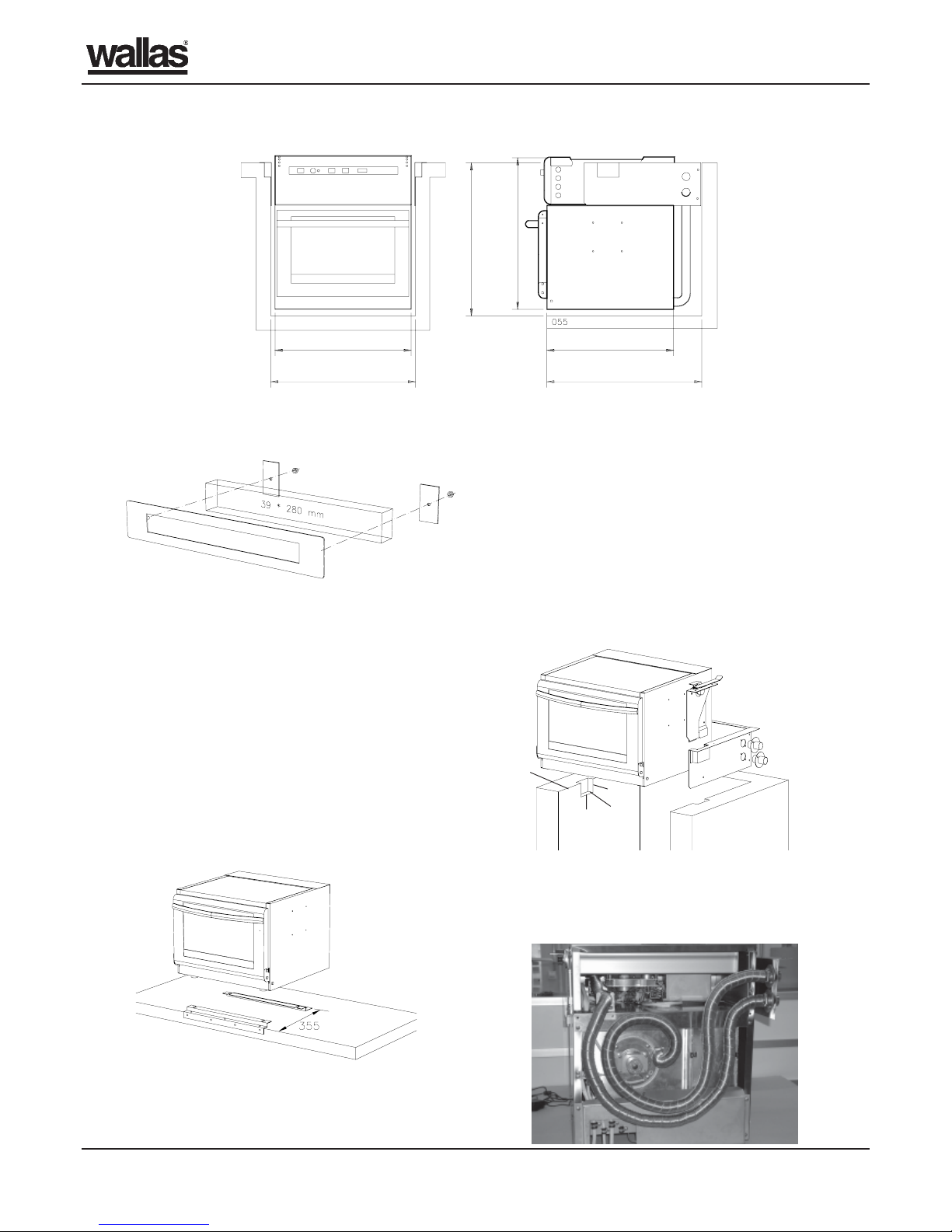
Figure 5: Minimum dimensions of the space required for installation of stove. When installing the stove into a fixed
position, the width and depth measurements of the installation opening are identical to those shown in the oven installation
diagram 495 mm and 530 mm. Figure 4. When installing a gimbal-mounted oven, the width and depth measurements of
the installation opening are identical to those shown in the installation diagram for the stove 510 mm and 550 mm. Figure
5.
Figure 6: The dimensions of the space required for
installation of the 96 D oven’s control panel. Heat will
make electronics life time shorter; It is not recommended
to mount the control panel right above the shutter of the
oven.
Figure 7:
Figure 8:
Figure 9: Installation of the exhaust pipes in a
gimballed stove. Length of the exhaust pipe: to the
right 900 mm and 1500 mm., to the left 1000 mm
and 1200 mm.
Fitting the Appliance into the
Installation Opening
Fixed Installation of the Oven or Stove
1.Fit the back edge of the fastening cleat for the rear
pads 355 mm from the front edge of the installation
opening.
2.Lift the oven into the installation opening so that the
rear pads slide into the grooves on the fastening
cleat.
3.Fit the fastening cleat for the front pads onto the
front edge of the installation opening.
4.Fit the oven with an exhaust pipe, which should follow
the most direct route to the lead-through. The exhaust
pipe are insulated with a second, larger diameter
metal pipe.
3.Attach the gimbal-mounting rockers to the oven or
stove.
4.Use screws to attach the rockers to the gimbalmounting frame.
5.For exhaust pipes not to prevent the oven movements
the pipes are formed into a loop behind the oven and
led through the apertures in the frame to the leadthrough. Figure 9.
6.Protect the exhaust pipe with a second, larger
diameter metal pipe.
7.The fuel hose and the wires must allow the unit to
swing freely in all conditions and they must not come
into contact with the exhaust pipe. The play is best
to turn under the oven.
510 mm
550 mm
min. 635 mm
475 mm 475 mm
530 mm
30
26
25
175
056
Gimbal-mounted Installation of the Oven or
Stove
1.Do not fit pads underneath the oven.
2.Fit the gimbal-mounting frame into the installation
opening.
SafeFlame 96 D / 97 D
3
30014
30012
30011
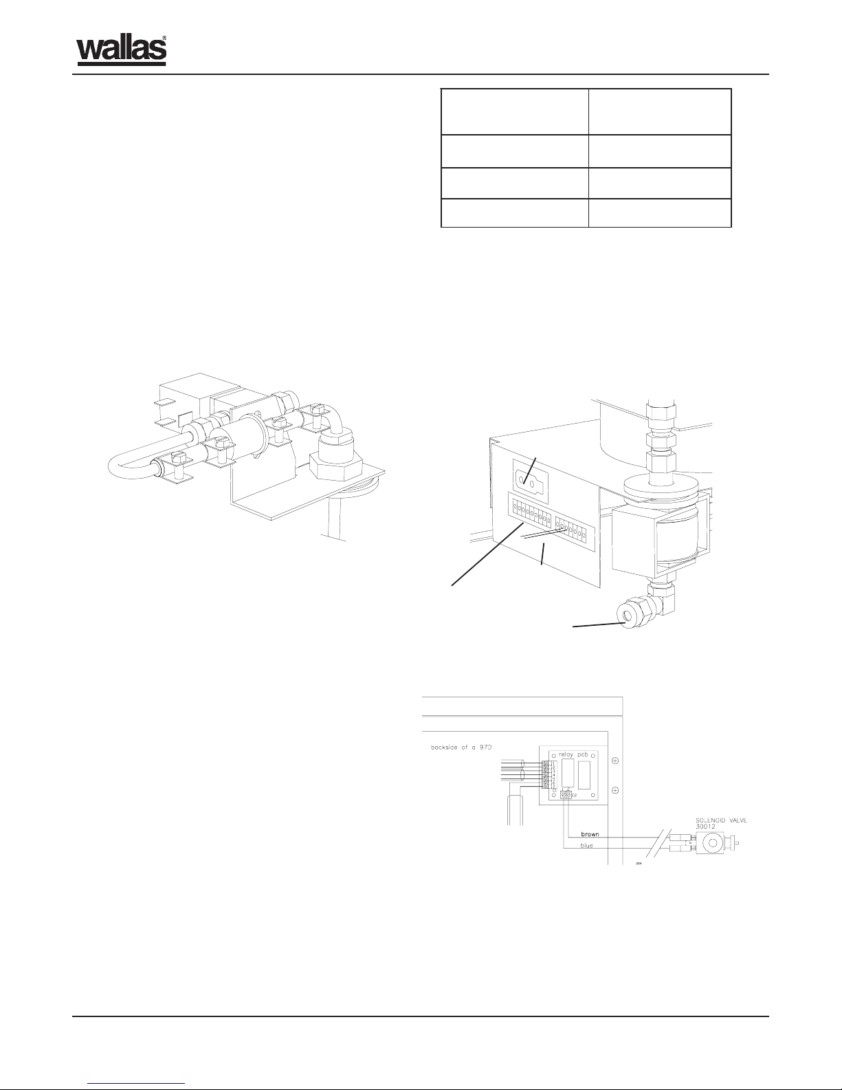
Figure 11:
Table 1:
- Inclusion of a solenoid valve in the fuel hose near the
tank is necessary if the tank’s fuel level is above the
oven’s or stove’s bottom.
- If the fuel tank is more than 0.5 m above or 1.5 m
below the oven or stove, check the fuel feed and
make any necessary adjustments in accordance
with the separate instructions.
- The fuel hose must always have a fuel filter .
- In the combined unit there is a T -connector for fuel
hoses. The common fuel hose of the oven and stove
is connected into the branch downwards so the play
can be turned under the oven.
- The fuel hose joints must be fully tightened!
Check the joining surfaces for dirt before
tightening.
Electrical Connection
Important:
- During start-up, the appliance uses approx. 8 amps
of current for 2.5 – 6 minutes.
- A 15 amp fuse must be mounted close to the battery .
- T ake the appliance’s power directly from the battery
terminals, not the fuse box or distributing box, to
minimise voltage loss.
- The cables must be protected if there is a risk of
mechanical damage.
- T able 1 shows the minimum diameter of the cables.
- Connect the electric cable’s red lead to the plus (+)
terminal and the black lead to the minus (-) terminal.
- The cables are protected by rubber rings. In the
protection balk down back there are fixing points
for both oven and stove cables. Care must be taken
that the wires don´t come into contact with the
exhaust. Turn the play under the oven.
Figure 12: Oven connection.
Connector for the oven control panel
Solenoid valve
Power cable
Fuel hose
Solenoid valve with 97D oven-stove unit
Installing the Lead-Through
Installation Considerations
- The exhaust pipe should be bent into the shape of a
gooseneck to prevent water from splashing into the
unit.
- The exhaust pipe must be insulated a bendable metal
pipe that is larger in diameter than the normal
exhaust pipe.
- The Insulation pipe is connected to the fresh air duct
of combination lead-through.
- In a metal-hulled boat it is recommended to insulate
the lead-through to prevent electro-chemical
corrosion.
- There is an separate instruction for lead-throughs.
Connecting the Fuel System to the
Boat’s Main Tank
If solenoid valve must be installed to the fuel system,
it must open when one or both appliances are used.
97D oven-stove unit has in build a relay pcb. Install
solenoid valve wires to connection C2. Solenoid valve
uses always two wires; these wires are included in
the solenoid valve kit 30012.
lacirtcelefohtgneL
)m(elbac
ehtfonoitces-ssorC
)²mm(elbac
4-04
6-46
6revo01
 Loading...