

wallas Safe Flame 800 Installation Instructions Manual
SafeFlame 800 / 220
1
INSTALLATION INSTRUCTIONS
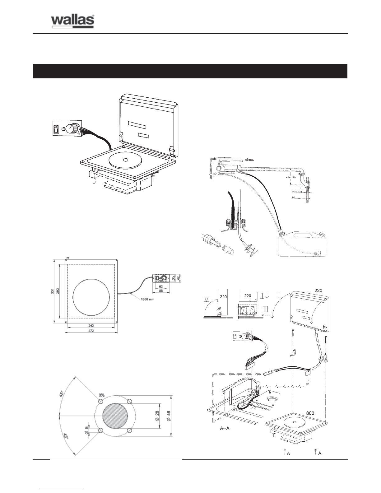
W allas Safe Flame 800 kerosen stove and 220 heat
blower lid
Figure 1:Wallas SafeFlame 800 and Wallas 220.
Figure 2: Flush opening size for stove is 280 x 242 mm
and Control panel opening is 62 x 35 mm. Control cable
length is 1.5 m. The stove requires for its ventilation to
avoid overheating an outlet opening of 30 - 40 cm
2
behind
the stove top and front of the stove. For example 3 - 4
about ø 2,5 - 3 cm holes or about 1,5 - 2 x 20 cm opening.
Figure 3: The “through hull” exhaust head 1066.
Figure 4: 1 Fuel suction line ø 5/2 m. 2 The return fuel
tube must have continuos fall to fuel tank with no loops
upward. All extra length is cut away below the tank adapter.
3 The end of the return tube must reach the bottom nib. 4
Filter head, sinterbronze. 5 Shield spiral hinders water
intake by holding the suction end free from tankbottom.
6 Exhaust tube 1028 ø 31/28 mm. Max length 5 m. 7 The
exhaust head 1066. 8 The fuel tank must always, under
all circumstances lie below the stove bottom level, secured
so it can not tip or come loose.
Figure 5: Installation of the heat blower lid
1
2
3
4
5
6
7
8
SafeFlame 800 / 220
2
OPERATION INSTRUCTIONS
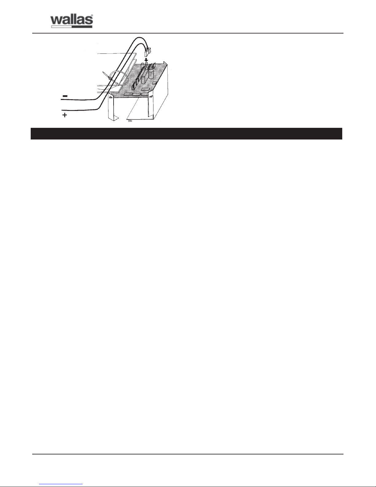
Figure 6:
- black
+ red
Safeflame stove 800
Function description
- Wallas 800 heater is a single hot plate compact stove.
- The combustion gases and also the water vapours
produced by the combustion are discharged out
which keeps the boat interior dry and fresh.
- The ignition and start are automatic and the cooking
effect steplessly adjustable.
- The stove top is stainless steel and the nitrided, anti-
rust coated hot plate of iron.
Start
- Cooker The priming and heating is started
automatically. The switch pilot lamp indicates that
the cooker is switched ON by switching ON the ON/
OFF switch. At st art the regulation knob should be
set on full effect until the red combustion control
lamp lights up. When switching off the cooker the
effect setting has no importance.
- A flashing switch lamp indicates too low supply
voltage caused by disharged battery, too weak
supply cable or poor contact in fuse or connections.
If flashing continues after the 2.5 min. priming (start)
cycle or occurs under operation the cooker will
switch off automatically .
- Re-start (after switching off) can not be made before
cycling the switch in OFF-position 5 min. and not
before the red combustion pilot lamp has gone out.
Combustion pilot lamp
- The red pilot lamp indicates that combustion is going
on. The lamp will normally light up in abt. 5 min.
after start, - if not, switch the ON/OFF switch to
OFF, wait abt. 5 min. and re-start.
- After switching of f the cooker the red pilot lamp will
light until the cooker is cooled down, - about 10
min.
- A flashing red light indicates that the overheating cut-
out has switched off the fuel pump and cooker
because of overheating. The overheating cut – out
and fuel feeding will reset automatically after the
cooker is cooled down. Before continuing the use,
clear up the reason for overheating and take the
necessary steps to eliminate it.
Effect regulation
- The effect regulation is stepless (abt. 500 –1 100 W).
- The regulation effect is almost instantaneous.
Switching off
- The cooker is switched off by turning the switch in
OFF-position. After this the combustion blower goes
for aftercooling until the red combustion pilot lamp
goes out.
- The battery supply to the cooker shall never be
switched off by a battery master switch before this.
Maintenance
- Dish washing agent and olive oli recommended for
cleaning and for protection of the hot plate after every
use.
The heat blower lid type 220
Function description
- The heat blower lid 220 blows the heat from the hot
plate to the cabin and converts the cooker in a
handturn an effective cabin heater. The blower lid
can be attached to the cooker also afterwards.
Start
- The blowers in the lid start automatically with some
minutes delay when the lid is closed and the lids
heat sensor feels the heat of the hot plate. The
blowers stop automatically when the hot plate is
cooled down after switching off and after rising the
blower lid.
SafeFlame 800 / 220
3
Old fuel – water in fuel
- Long storage can cause water condence which
produces wax in paraffin oil. As this will fill up fuel
pumps and burner wicks, it is suggested that 3 –
5% of Iso-Propyl alcohol is mixed with the fuel.
- Filled up fuel pumps and burners can be cleaned by
running the heater in cold state for 15 - 30 minutes
with Iso-Propyl alcohol. For this remove the fuel pipe
from the tank, start the heater and allow it to run for
10 minutes without fuel before using the alcohol.
Fuel quality
- The fuel must be premium grade paraffin with a smokePoint of 35 mm, which should conform to BS 2869.
Suitable types are “Pink” and “Blue” in U.K., Esso
Blue in Skandinavia and in Europe generally the Esso
Exol D 60 (D180 – 220).
Water int ake through exhaust head
- The exhaust heads 2466 (cookers) and 2460
(heaters) will, opened, leak water in the heater when
submerged or flushed.
- The penetrating water can then damage the heaters
electronics or blower motor.
- Limited water penetration in a hot running heater may,
however, not be harmful as such water is immediately
vaporized and expelled.
IMPORTANT TO OBSERVE
- When closed these exhaust heads do not take water
in the heater under above circumstances, provided:
1. that the exhaust head is properly closed.
2. That the telescope inner tube slide joint of the
exhaust head 2460 is tightened by Silicon grease.
The greasing is made in factory but it can be removed
in mounting – must be checked. New Silicon grease
is available from Wallas-Marin representatives or
Wallas-Marin.
3. That the gaskets in the exhaust head are not
defective and that the take through deck joint will
not leak.
- Observe, that the exhaust heads are not pressure
water tight when closed and will not stand continuous
submerging or overflooding without some leaking.
- The water intake can be reduced through raising the
exhaust head from the deck with the collar 2069 or
by using the through hull boardfittings 3467 or 1066
(for cookers) or 3468 or 2467 (for heaters).
Current supply connection
- To reduce radio interference created by the heater
and to avoid accindental supply interruption to an
operating heater, we suggest using a cable direct to
the ships battery and not via the master switch. This
cable must be at least (AWG 13) 2,5 mm² [min 4
mm² (AWG 1 1) with Ceramic cookers and 150 ovens]
with an own. appr. 15 A fuse and own master switch.
TECHNICAL SPECIFICA TIONS
Table 1:
tceffEtaeH
/008
022
W0021tuoba
leuF008lioniffaraP
noitmusnocleuF008h/l31,0-70,0
egatloVylppuS
/008
022
V21
noitmusn
octnerruC008A51,0tuoba
noitmusnoctnerruC022A4,0tuoba
thgieW008gk7,5tuoba
thgieW022gk6,2tuoba
WARNINGS
- Never leave the cooker on full effect alone for longer
time without supervision.
- Before leaving the yacht always check that the cooker
has not been left on!
- Avoid unnecessary, quick forth and back adjusting
of the effect knob, this can cause sooting!
SafeFlame 800 / 220
4
MONTAGEANLEITUNG
Wallas SafeFlame 800 Petroleumkocher und Wallas 220
Wärmegebläsedeckel
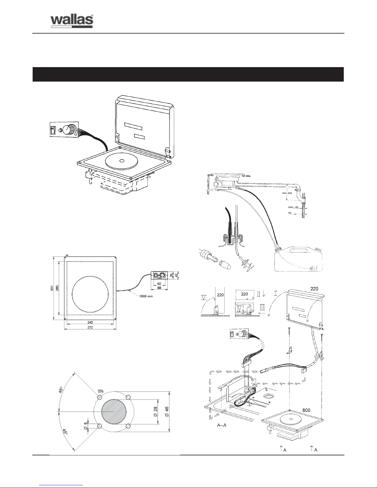
Abb. 1: Wallas SafeFlame 800 und Wallas 220.
Abb. 2: Masse für Einbauöffnung sind 280 x 242 mm und
Kontroll Panel Einbauöffnung 62 x 35 cm. – Kontrollkabel
Länge 1.5 m. Der Herd fordert für die notwendige
Ventilation eine Luft einnahme – Öffnung um 30 – 40 cm
2
unter dem Herd, wahlweise in Form von 3 - 4 ST Löchern
mit einem Diameter von 2.5 – 3 cm oder ein Spalt mit ca
20 cm Länge und 1.5 – 2 cm Breite.
Abb. 3: Lochbild für Durchführung des Abgasstutzens
1066. Durchführung muss sorfältigt abgedichtet werden,
z.B. mit Silicon.
Abb. 4: 1 Ansaugschlauch ø 5/2 mm. 2 Der
Brennstoffschlauch muss fallend zum Tank, ohne
Schlingen oder Biegungen aufwärts gelegt werden.
Überflüssige Länge sofort unter Tankdurchführung
abscheiden. 3 Die Schlauchende muss den
Bodennabsatz erreichen. 4 Filterkopf, Sinterbronze. 5
Schutzspiral hindert Wassereinahme durch halten die
Einsaugende frei von T ankboden. 6 Abgasschlauch 1028
ø 31/28 mm. Max. Länge 5 m. 7 Abgasstutzen 1066 für
Rumpfdurchführung. 8 Brennstofftank muss so placiert
werden, dass der Brennstoffniveau im Tank immer, unter
allen Verhältnissen unter dem Kocherboden bleibt. Der
Tank muss gestützt werden, um Fallen und Loskommen
zu verhindern.
Abb. 5: Montageanleitung für Wärmegebläsedeckel.
1
2
3
4
5
6
7
8
 Loading...