

wallas M40 Installation, Operation And Service Instructions
T0209 T0209

M40
T0209
INSTALLATION INSTRUCTIONS
SPACE HEATER LOCATION
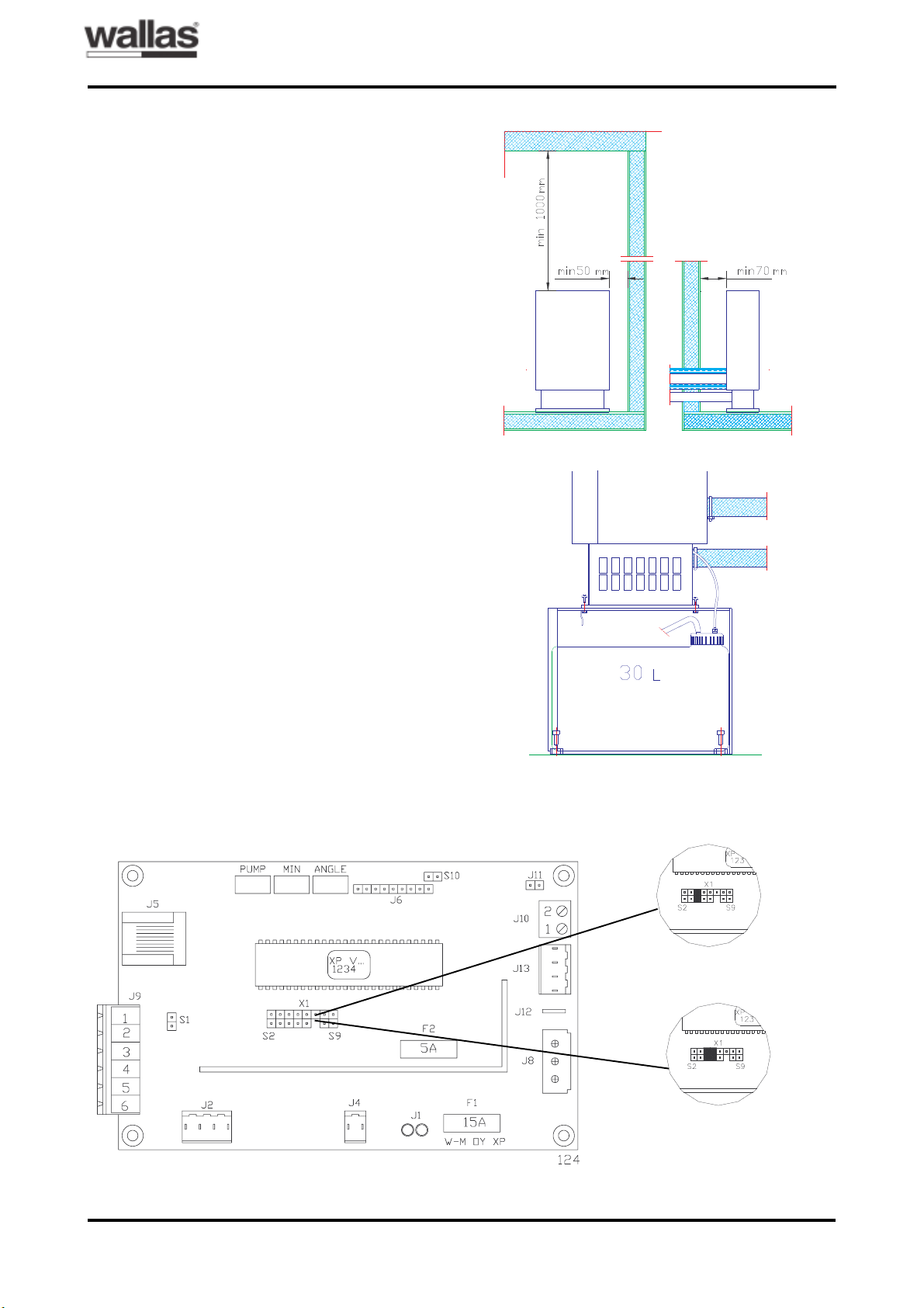
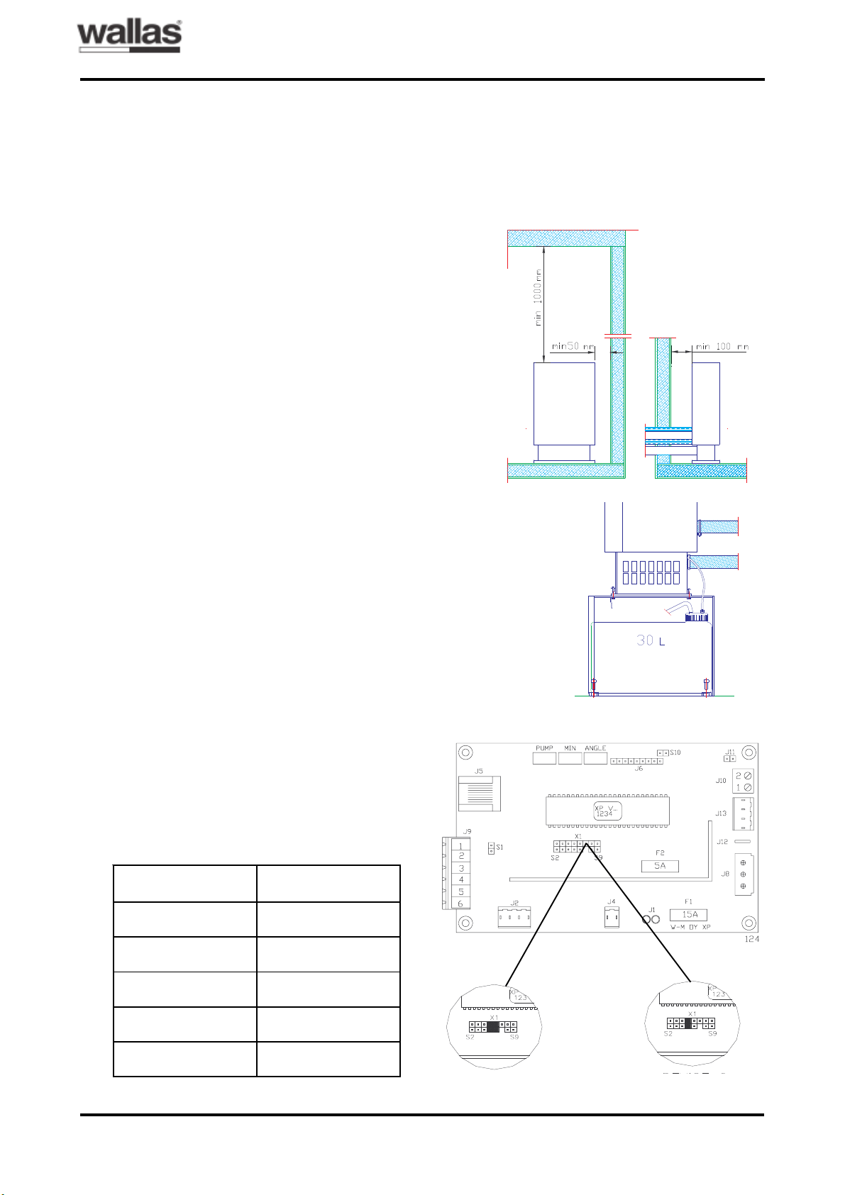
1.Free distance from the surrounding walls as
shown in fig. 1.
2.The spaces between the walls must be kept
clean and free from dust, litter and foreign
objects.
3.The air inlets of the lower part of the heater
jacket at the front, sides and back must be
kept free from objects and hindrances preventing air intake.
4.There must not be any surfaces, constructions or objects presenting fire hazard or preventing the heat flow directly above the heater closer than 1 metre from the top of the
heater. Fig. 1.
5.The heater must be properly fastened by
screws to the floor or to its foundation casing,
which is also fastened to the floor. The equipment must be in vertical position. Fig. 2.
Fig. 1.
Fig. 2.
6.The heater must be placed so that no water
can drip, flow or splash into it.
7.The maximum lenght of uninsulated exhaust
pipe is 3 m, insulated 6 m.
8.If needed notice the change of air density by
changing mountain parameters on the electronics (PCB), when the heater is situated
over 1500 m altitude above the sea level for
example on an arctical hill.
Fig. 3.
Over 1500 m
Under 1500 m
1 / ENGLISH
M40
T0209
INSTALLATION INSTRUCTIONS
TANK LOCATION
1.The fuel tank is good to be placed beneath
the heater foot. Fig. 4. (The surface of the
liquid fuel must be beneath the foot). When
the liquid surface is above the heater foot, a
magnetic valve is recommended to install
near the tank end.
2.The fuel tank may be installed into its foundation casing or outside, for example, into
the basement of the house or inside a suitable, protective casing. The fuel tank and
hose must be protected from direct sunlight.
3.The fuel hose inlet through the constructions
must be protected by a metal pipe.
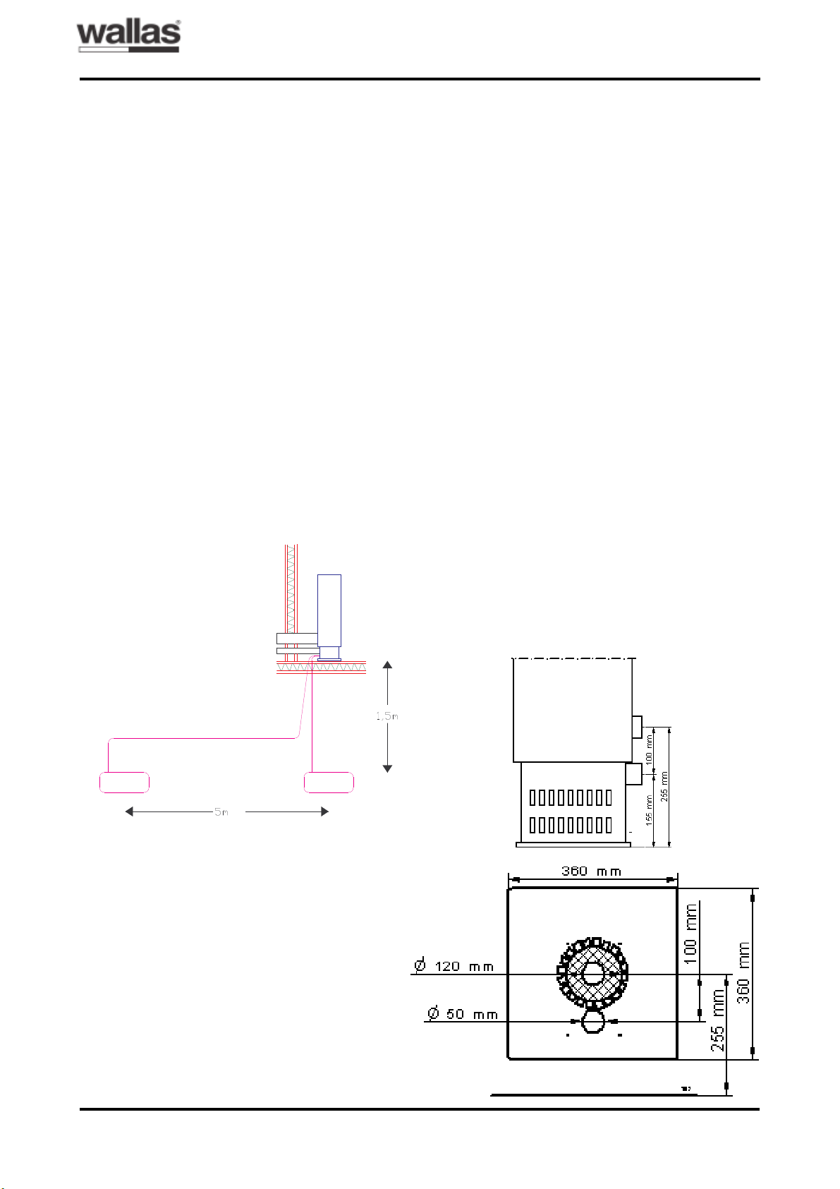
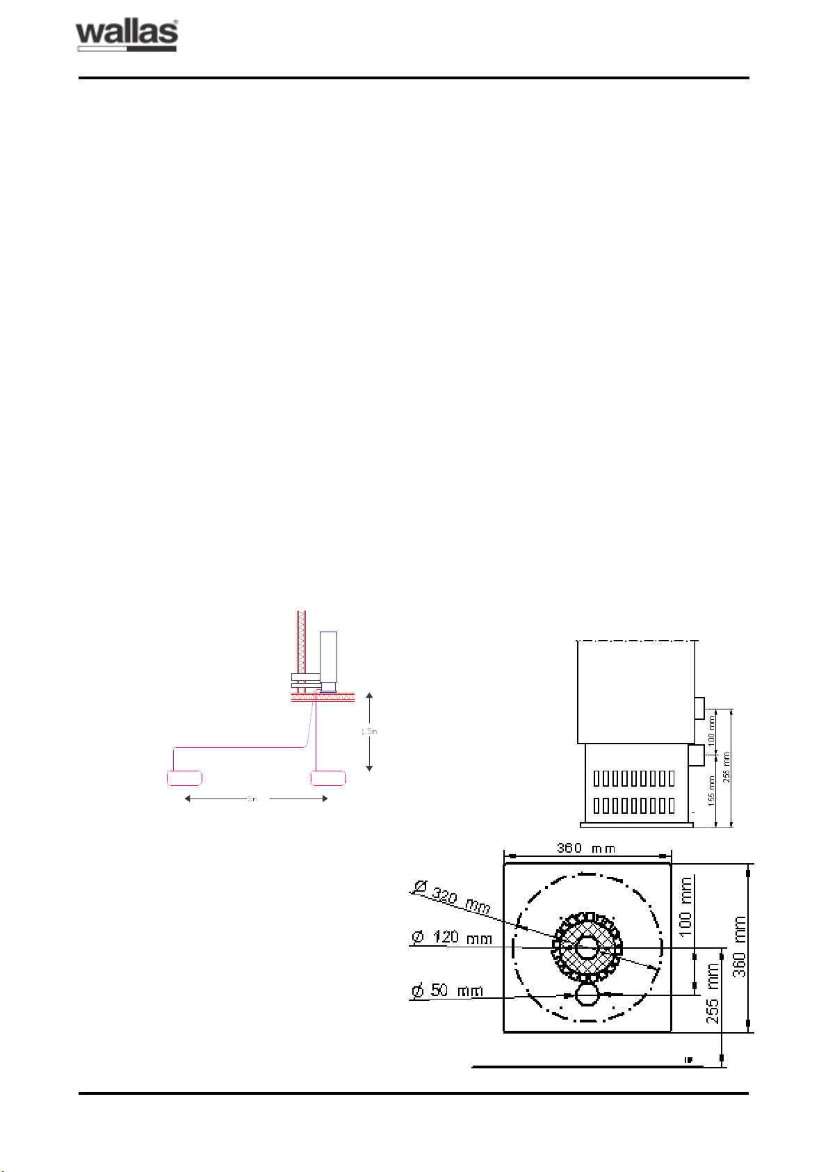
4.The basic length of the fuel hose is 3 metres. It may be extended by using a 2-metre
extension hose which makes the total hose
length 5 metres. The hoses are linked by
using threaded quick connectors. Fig. 4
shows the maximum limits of the installation.
Fig. 4.
N.B. The voltage must be primarily taken directly from the battery, not from the control unit
of the solar battery. This will ensure that the
system bears the ignition current and does not
receive excess voltage. Contact your system
supplier for further details.
INSTALLATION HOLES
1.Choose the place for the heater. See instructions above.
2.Exhaust gases shall always be led out. If desired, they can be led out directly through the
wall. In this case, the combustion air is also
taken from outside, which contributes to balancing the pressure fluctuations caused by
the wind. See the separate leaflet describing
installation alternatives.
3.Make holes through the wall according to the
dimensions given in fig. 5. In the case of duct
installation, the hole for exhaust gas (diameter 120 mm) shall be dimensioned in its correct location. Make a separate hole for fresh
air (diameter 50 mm) in the fresh air duct or
through the floor. (For sizes of the holes, see
fig. 5). As far as a duct installation is concerned, the fire ventilation air may also be
taken from indoors.
BATTERY LOCATION
1.The equipment contains 4 metres of electrical wire with a thickness of 4 mm2. In case
the distance between the battery and equipment is 6 metres, the cabel thickness must
be 6 mm2 and so on.
2.The electrical wires must be protected by placing a 15 A fuse at the battery end of the positive cable of the electrical wire.
3.The battery should be located so that there
will not be any danger when the battery is
charged or used.
Fig. 5.
2 / ENGLISH
M40
T0209
INSTALLATION INSTRUCTIONS
INSTRUCTIONS FOR INSTALLATION
THROUGH THE WALL
1.Install the covering plates on the wall and tighten the joint by acrylic mass. Put a plate with
8 holes on the outer wall.
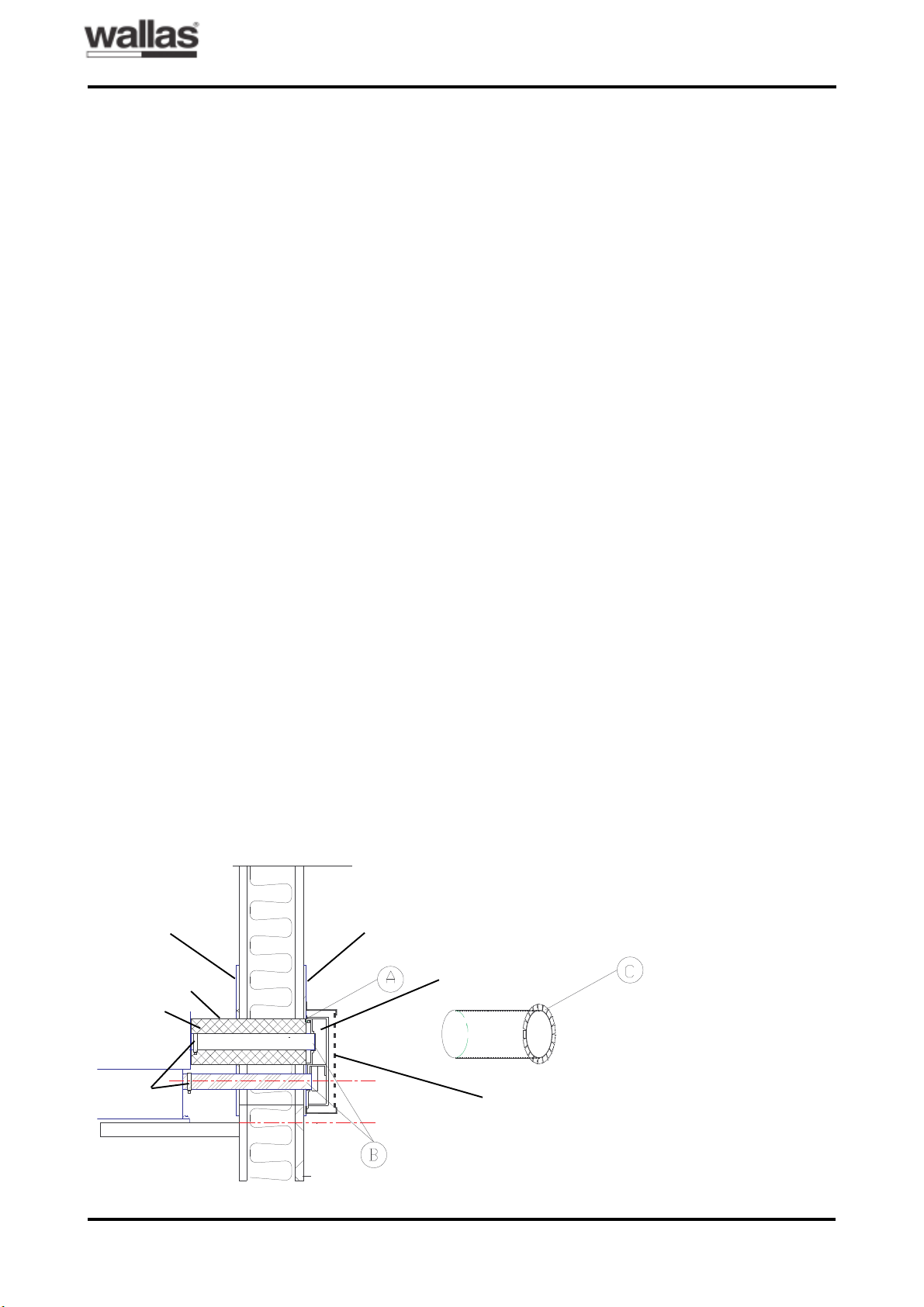
2.Cut the ducts and insulating channels as
shown in fig. 6 (items A and B).
ACut them so that the insulation will be 10
mm outside the wall (the insulating plate
shall also be 10 mm outside the wall).
BCut them so that the ducts will be 40-45
mm outside the wall.
3.Fasten the ducts to the heater by using hose
clamps. The exhaust gas pipe must be tightened properly by using power press binding.
4.Mount the heater and its ducts to their places.
5.Mount the insulating channels and protective plate from the outside. Cut small tongues
on one of the protective plates (Fig. 6, item
C) and install this one with the tongues
against the covering plate on the outer wall.
6.Install the exhaust gas discharge casing and
the shroud (protection against contact) so
that the pipe ends reach the limit stops of the
casing. Tighten the joint between the casing
and covering plate by using acrylic mass.
7.Fasten the heater on the floor or foundation
casing by screws.
Fig. 6.
8.The equipment is ready for use after the
electrical wire and fuel hose have been connected.
INSTRUCTIONS FOR INSTALLATION IN
THE DUCT
1.Cut the hoses, insulating channels and protecting plates so that they each the inner surface of the duct.
2.Fasten the hoses to the heater by using
clamps. The exhaust pipe must be tightened
properly by using power press binding.
3.Mount the heater to its place.
4.Tighten the joint between the exhaust pipe
and the duct by using acrylic mass.
5.The equipment is ready for use after the
electrical wire and fuel hose have been connected.
N.B. When taking the combustion air from under the floor, make sure that the base floor has
sufficient ventilation. Install a protective spiral
at the end of the hose.
- In a high (over 5 metres) and large (crosssectional surface over 15 x 15 cm) duct, exhaust gases are cooled down so that the
moisture in them is condensed, thus causing
the chimney to decay, as well as decreasing
the draught. Therefore, a brick duct should
be lined with stainless steel pipe (diameter
50-70 mm), as well as filling the space between the pipe and duct by, for example, expanded clay.
- Air for fire ventilation cannot be taken from
the same duct through which exhaust gases
are discharged.
Covering plate
Insulating plate
Insulating
channels
Hose
clamps
Covering plate
Discharge casing
Shroud (protection
against contact)
3 / ENGLISH
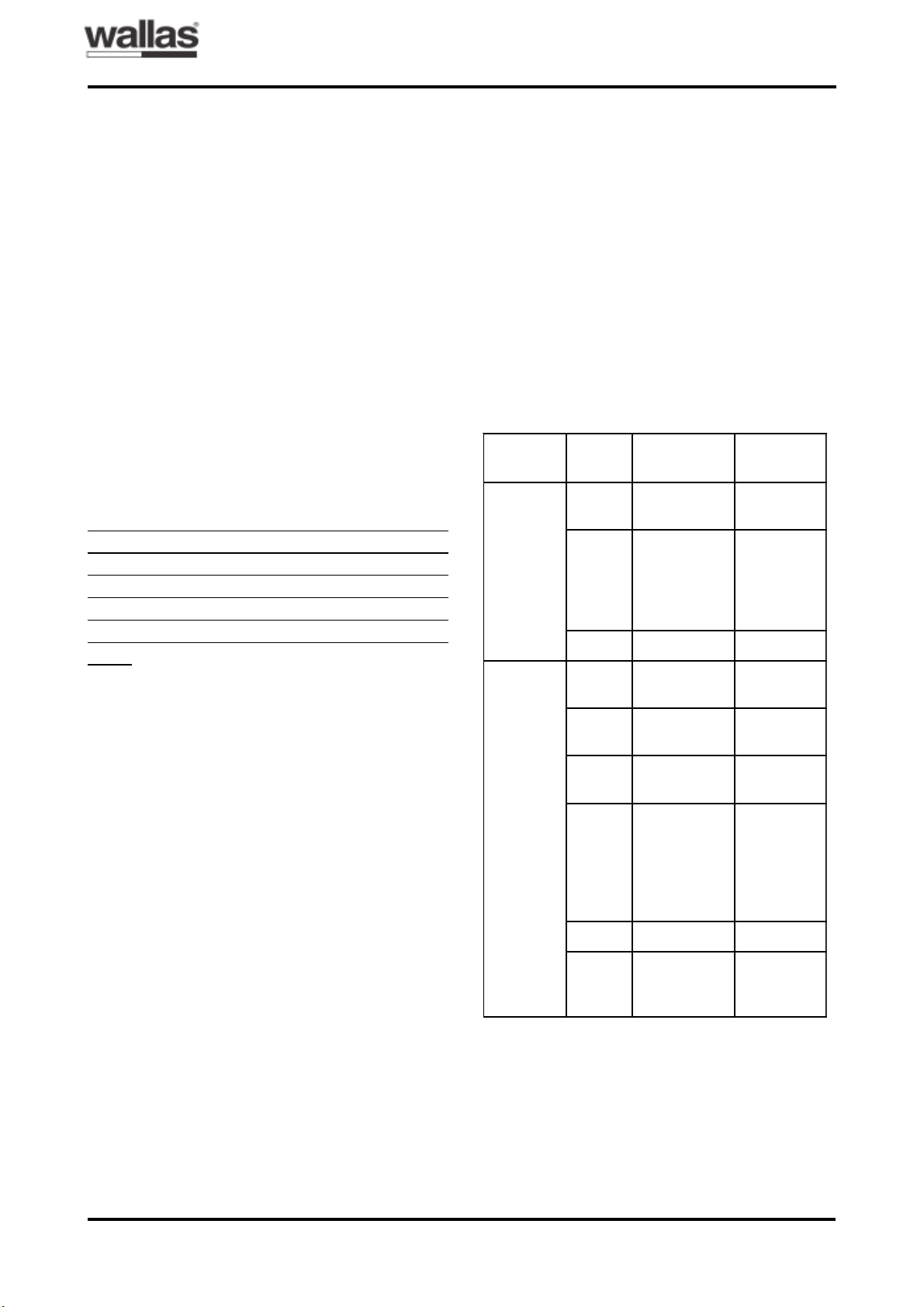
M40
ruoloC
DELfo
gniknilB
lavretni
gninaeM
noitcnuF
wolleY
sthgiL
.ylsuounitnoc
notnerruC
deR
sthgiL
.ylsuounitnoc
,thgilrenruB
nehw
noitsubmoc
nugebsah
.yllamron
deR s52,0 gniloocretfA
;eruliaF
eruliaf
langis
5sekat
setunim
retfadna
ylnotaht
DELder
.gniknilbsi
wolleY s2
gulpwolG
eruliaf
wolleY s2ajs521,0
nafrenruB
eruliaf
wolleY s52,0
rednU
egatloV
wolleY
derdna
s521,0
;gnikcoL
ecapseht
siretaeh
gnikcol
2retfa
*.tratsdeliaf
deR s52,0 taehrevO
deR s03
retfasthgiL
eruliaf
.langis
T0209
OPERATION INSTRUCTIONS
FUEL
The following alternative fuels can be used in
the space heater :
Remember to take operating temperature
into account while choosing the fuel type.
Following temperature limits are for reference only. Check temperature limits from
your local fuel supplier.
- Furnace oil / Diesel oil, summer quality, ambient temperature must be higher than –5°C
- Furnace oil / Diesel oil, winter quality, ambient temperature must be higher than –24°C
- Furnace oil / Diesel oil, arctic quality, ambient temperature must be higher than –40°C
- Paraffin (kerosene), ambient temperature
must be higher than –40°C
If ambient temperature is lower than recommended fuel can be waxing (fuel becomes
cloudy). Wax can block fuel filter and pump.
Wax won’t dissolve until the ambient temperature is clearly over 0°C. In winter conditions
arctic quality or paraffin (kerosene) must be
used.
N.B. Do not start at the same time as the battery will be charged from a generator or battery charger (danger of over voltage)
NORMAL START-UP
1. Press the starting switch on: position I. The
red signal light comes on after about 2.5 - 4
minutes from the start-up, and then the combustion is normal. After the start-up stage
(about 5 minutes), the heater’s output remains at the set value.
SIGNAL LIGHTS OF M40 CONTROL
PANEL
The less aromatic substances are contained
in the fuel, the less crust will be formed. The
aromatic substances content in normal fuel oils
is about 35 - 40%, in dyed city-diesel oils (for
example, Tempera 3G and 5G) about 20%. The
aromatic substances content of paraffin is
about 0.5%, and consequently, almost no crust
is formed during combustion.
THE FIRST START-UP
1.Press the starting switch on: position 1.
2.The device does not necessarily start at the
first time, as the fuel hose is empty. In such a
case, the red light begins to blink after about
4.5 minutes from the start-up. Press the starting switch to position 0. The device cannot
be re-started until both signal lights are out
(after-ventilation period). Start again after the
signal lights have gone out. The red signal
light comes on after about 2.5 - 4 minutes
from the start-up, and then the combustion is
normal.
* Opening of the locking:
1 Switch ON the heater (blinking of locking).
2 Disconnect the main current wire of the heater (heater (blinking) switches off).
3 Reconnect the main current wire (yellow LED lights
1 - 3 second).
4 When yellow LED dies switch OFF the heater.
4 / ENGLISH

M40
T0209
CHECK-LIST AT SERVICE FAILURES
OPERATION INSTRUCTIONS
The fuel is not moving: The movement can
be checked by lifting the suction hose out of
the tank for a few seconds; there will be an air
bubble moving with the fuel.
- Check the tightness of the joint: if necessary,
make the joint tighter.
- Check the hose: replace a leaking hose with
a new one.
- Make sure that the pump receives voltage;
the pumping sound or voltage variation when
measuring the voltage.
No voltage is received: the yellow light is not
on.
- Check the charging of the battery.
- Check the connections of the battery or power-supply unit.
- Check if the automatic fuse has tripped and
come up, press it down if necessary. Check
the main fuse connected to the electric conductor and replace it if necessary.
Under-voltage: the yellow light is blinking.
- Charge the battery or replace it with a more
powerful one.
- Replace the electric conductors with thicker
ones; see installation instructions.
Too much fuel is received: the heater is overheated and cuts off its function by itself.
- Check that the fuel surface of the tank is below the lower surface of the heater
- The exhaust gas or fire ventilation hose is
blocked.
- Remove obstacles and blockages
Fuel and voltage is received normally, but
the device will not start:
- Check through the inspection port whether
the glow plug is glowing at start-up, change
it if necessary.
- Check the fuel composition and if there is any
suspicion that water may have condensed
into the tank, remove the water; see maintenance instructions.
N.B. The device cannot be re-started until the
red and yellow signal lights have gone out.
If necessary, contact the nearest Wallas service or your supplier.
TECHNICAL DETAILS
Fuel:
Furnace oil / Diesel oil (anti-freezing properties according to the operating conditions) or
paraffin (kerosene)
Fuel consumption:
M40: 0.16 - 0.4 litres/hour = 3.8 – 9.6 litres/
day
Thermal power:
M40: 1600 – 4000 W
Power adjustment:
Stepless manual adjustment or room thermostat
Starting:
By manual switch or automatic, weekly timer
(additional equipment) or by remote control
starter (additional equipment)
Operating voltage:
12 V. Power source: battery or Wallas powersupply apparatus equipped with a 12 V/15 Ah
mini battery.
Current consumption:
0.2 – 0.4 A = 4.8 – 9.6 Ah/day
Heater current 8 A for 4.5 minutes after startup.
Dimensions and weight:
M40 730 x 440 x 240 mm / 25.5 kg
5 / ENGLISH
M40
T0209
SERVICE INSTRUCTIONS
The fuel contains aromatic substances that
form crust at the bottom of the burner. The
speed of encrustation depends on the quality
of the fuel and the output of the heater, and
consequently, the need for service may be varying. During servicing, the crust will be removed from the burner and the fuel needle and
bottom carpet will be replaced by new ones, if
necessary.
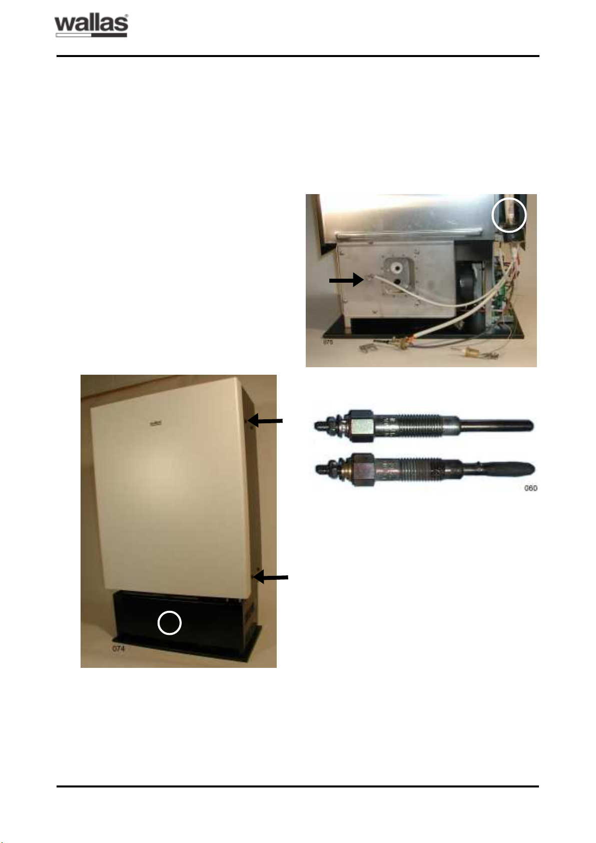
Cleaning of the burner
Lift the protective grating of the heater. Open
the front wall of the heater by lifting the wall
upwards. After this, the front wall can be pulled
out. The front wall is fastened with tongues to
the screws on the sides, loose the screws, if
necessary. Arrows in fig. 7. Detach the protective plate of the plinth by undoing the screw in
the middle. See the circle in fig. 7. Pull the protective plate forwards and lift it up.
Fig. 7: M40 heater.
temperature sensor carefully. If the packing has
become brittle, it must be replaced with a new
one. If the glow plug is damaged, replace the
old plug with a new one. Fig. 9 shows an intact
glow plug and a typical glow plug in short circuit. A glow plug does not usually look different
if there is a cut-off.
Fig. 8: How to detach the temperature sensor, glow
plug and fuel needle.
Glow plug
Temperature sensor
A
B
Detach the screw and clamp of the temperature sensor and the corresponding glow plug
clamp from the combustion chamber cover.
See fig. 8. Pull the glow plug and temperature
sensor carefully out; do not pull from the wires
of the parts. Remove the white packing of the
Fig. 9: Intact glow plug (above) and damaged glow
plug in short circuit (below).
Unscrew the fuel needle clamp and pull the fuel
needle carefully out by rotating it. See the arrow in fig. 8. The fuel needle is equipped with
a locking ring that defines the depth to which
the needle is installed. In model M40 the installation depth is 50 mm. If the fuel needle is
blocked, replace it with a new needle by pulling the fuel hose out of the upper clamp of the
pump and install the hose for the new needle.
See the circle in fig. 8. Undo the 5 fixing screws and one distance screw on the combustion chamber cover. Detach the combustion
chamber cover.
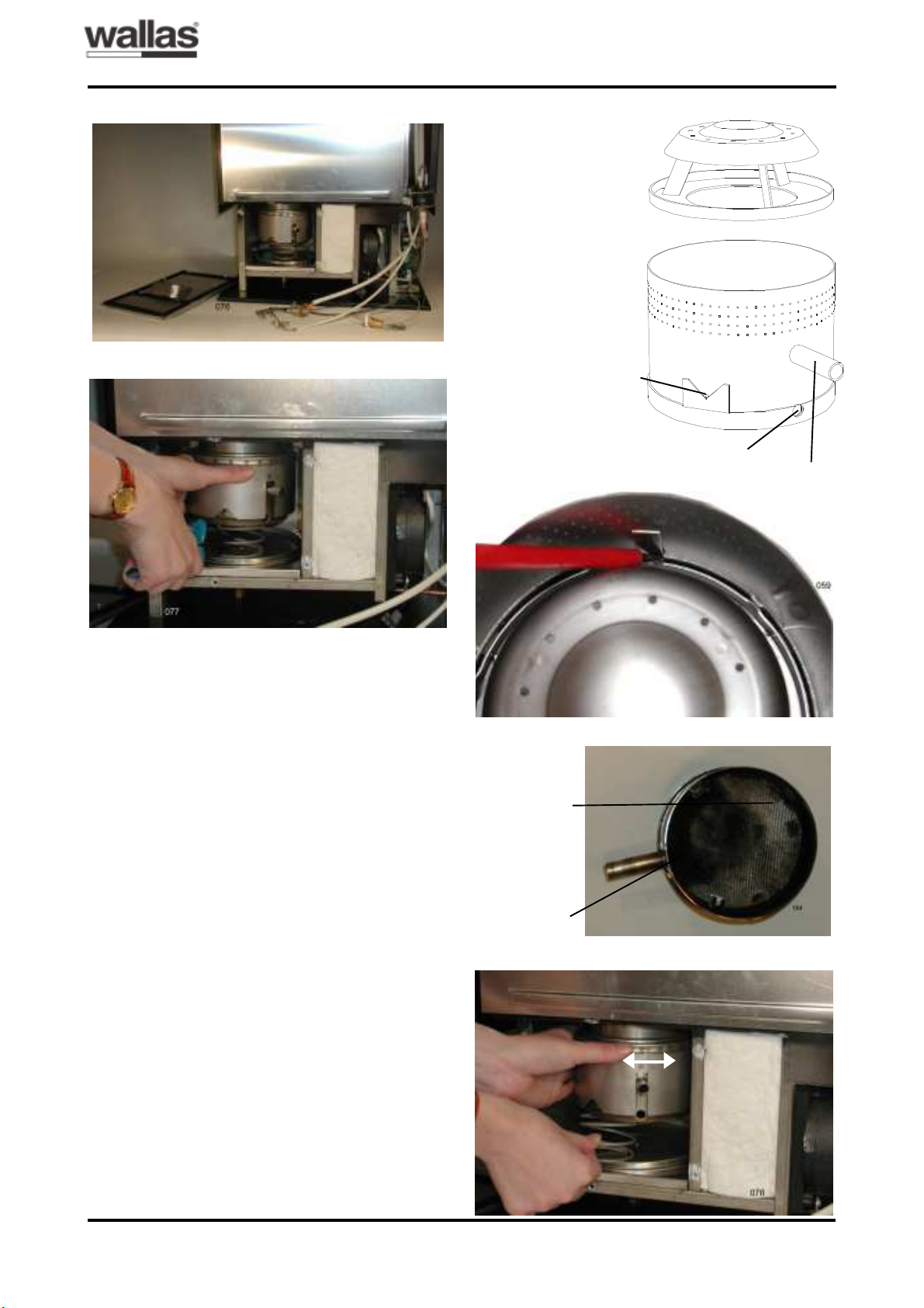
The packing inside the combustion chamber
cover must be intact as shown in fig. 10. Detach the burner assembly from the heater by
pulling out the spring that holds it in position.
See fig. 11.
6 / ENGLISH
M40
T0209
SERVICE INSTRUCTIONS
Fig. 10: M40 burner chamber opened.
Fig. 11: Detaching the burner.
Fig. 12: M40 burner parts.
Heat radiator
Burner cylinder
Fuel needle hole
Glow plug hole
Fig. 13: Detaching the heat radiator.
Temperature
sensor pipe
Fig. 12 shows the burner parts of M40. Detach the heat radiator by pressing the locking
tongue towards the burner cylinder wall and by
inclining the heat radiator. Fig. 13.
Crust is mainly formed on the bottom of the
burner cylinder. Scratch the crust carefully off,
for example, by using a screwdriver. If necessary, also clean the walls of the burner cylinder
and the heat radiator. It is advisable to replace
the bottom carpet in position when cleaning
the cylinder. Fig. 14. The bottom carpet acts
as a heat insulator of the burner cylinder during ignition, and consequently, the carpet must
be intact at least under the glow plug.
The burner is reassembled in the same way
as it was demounted, but in the reverse order.
When assembling the burner cylinder make
sure that the heat radiator is locked into its
position. To secure the locking, tap the burner
upside down, which makes the heat radiator
come off from its clamps, if it is not locked.
When installing the burner assembly move it
back and forth to make it settle tightly into the
heat exchanger. See the arrows in fig. 15. Turn
the burner to its position and push the spring
under the burner. Fig. 15.
Fig. 14: Burner cylinder.
Bottom carpet.
Crust
Fig. 15: Installation of the burner.
7 / ENGLISH
M40
T0209
SERVICE INSTRUCTIONS
The fuel needle is in correct position, when it
is bent to the right (towards the fuel pump). To
prevent the burner chamber cover from
sticking, it is advisable to apply heat resistant
grease on the fixing screws.
Checking the function of the heater
The functioning of the burner must always be
checked after the heater has been serviced.
- Start the heater and let it burn for 15 minutes.
- Check through the inspection window that the
heat radiator is glowing red and that the flame is burning smoothly.
- There should be many separate flames with
smooth edges in the burner. The flame may
be either all blue or blue and yellow.
- If the flame is burning smoothly and the heat
radiator is red, the burner and heater are functioning normally.
- If the flames cannot be discerned from each
other or if the flames are all yellow or entangled, there are air leakages in the burner. In
this case, reopen the heater and check all
the burner joints for air leakages.
- An unstable burner flame during operation is
probably a sign that the burner needs cleaning.
Fuel system and electronics card
Measuring the fuel feed
If any parts of the fuel system have been replaced, the fuel feed of the heater must be
checked by measuring it.
1. Start the heater at full capacity.
2. Pour some fuel into a measuring glass, e.g.
50 ml. Place the fuel pipe into the measuring
glass and start the clock at the same time.
3. Take the fuel pipe out of the measuring glass
after six minutes.
4. Multiply the amount of fuel in millilitres consumed in six minutes by ten to obtain the fuel
consumption per hour. Normal fuel consumption at full capacity is 0.4 ± 0.02 l/h.
5. Compare the measured value with the normal value; if there are differences, adjust the
fuel feed by turning the trimmer shown in fig.
17.
At the same time, it is easy to check the power adjustment of the heater.
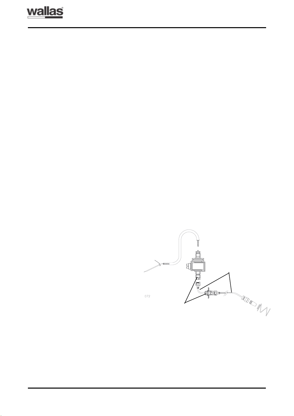
Fig. 16: Fuel system parts.
Fuel feed
pipe
Male connector for suction hose
Fuel pump
Fuel suction hose
Protective spiral
Filter
head
8 / ENGLISH
M40
T0209
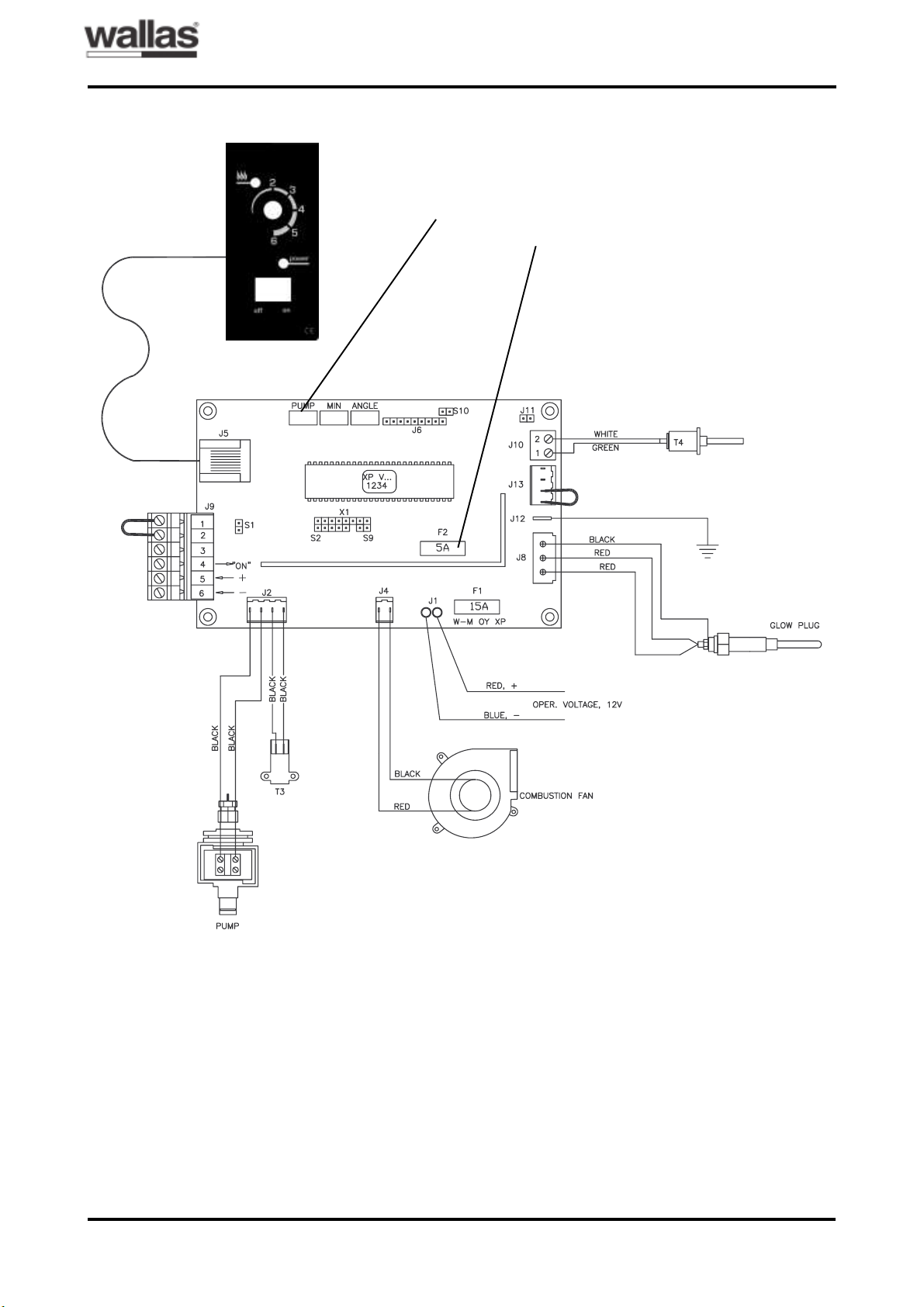
Fig. 17: Electronics card connections.
SERVICE INSTRUCTIONS
Connection to
thermostat and
remote control
Fuel feed trimmer
Fuse,
slow 5 A
9 / ENGLISH
M40
T0209
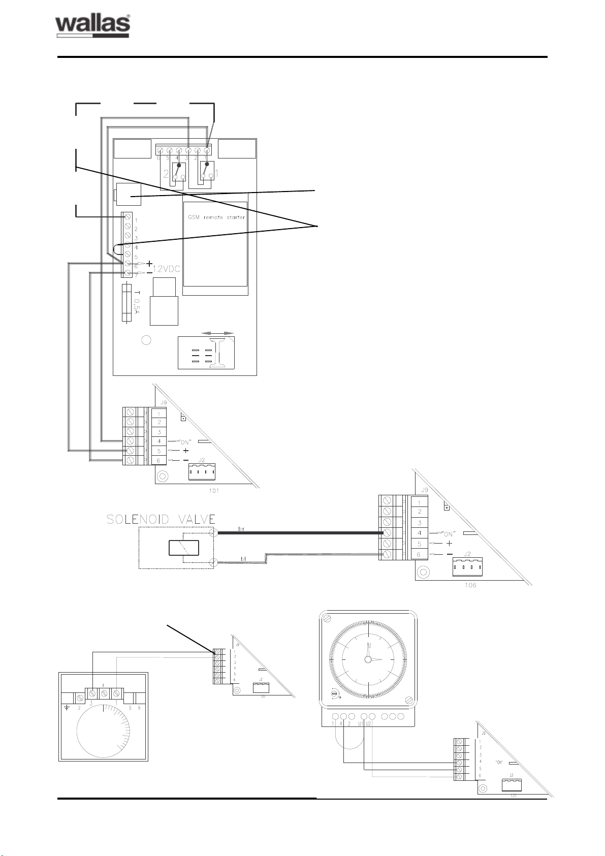
Fig. 18: Connecting a 4420 GSM remote control to the heater.
ACCESSORIES´ CONNECTIONS
Temperature sensor
Alarm
Fig. 19. Connecting a solenoid valve to the heater.
Fig. 20. Connecting a room thermostat (a) and a weekly timer (b).
a.
The short-circuit loop shall be eliminated.
b.
10 / ENGLISH
M40
gatnitfulsgninnärbröF
:kramrevö
m0,1
:gninnymsterörsagvA
kramnavO m1,1
trabsgninppönårF
retsnöf
m0,1
gninppösnoitalitnevnårF m5,1
rrödvanadisrellenavO m5,0
T0209
MONTERINGSANVISNINGAR
Värmeaggregat Wallas M40: Monterings-, bruks- och underhållsanvisningar / Sverige,
Finland
Notera i Sverige; Anvisningarna är godkända av SP med nr E12810. Typgodkännandennr. för M40 nr SP 585 K.
För att försäkra sig om en riktig installation, skall skorstensfejare i det berörda distriktet kontaktas. Före användin-
gen skall alla anslutningars (rökgaser, förbränningsluft, bränsle, rökgasrörets mynning) täthet kontrolleras.
PLACERING AV VÄRMEAGGREGAT
1.Fritt avstånd till omgivande väggar enligt figur 1. Övriga minimiavstånd i Sverige enligt
tabell 1.
2.Utrymmena mellan aggregat och väggar skall
hållas rena och fria från damm, skräp och
främmande föremål.
3.Luftingsöppningarna på framsidan, sidorna
och baksidan av aggregatets hölje (dess
nedre del) skall hållas fria från föremål och
hinder som hindrar ett fritt luftintag.
4.Det får inte finnas ytor, konstruktioner eller
föremål som är brandfarliga eller hindrar värmeströmningen rakt ovanför värmeaggregatet inom ett avstånd av 1 m från aggregatets
övre yta. Se figur 1.
5.Värmeaggregatet skall fästas stabilt vid golvet eller stativhöljet med skruvar. Även stativhöljet fästs vid golvet. Aggregatet skall stå
i lodrätt läge. Se figur 2.
Figur 1.
Figur 2.
6.Värmeaggregatet skall placeras så att vatten inte kan droppa, rinna eller stänka på det.
7.Obs! Den maximala längden för ej isolerat
avgasrör är 3 meter, för isolerat 6 m.
8.När aggregatet används på högre altituder,
t.ex. i fjällen över 1500 m kan luftdensitetens
ändring tas hänsyn till genom att efter behovet koppla bergsparameter på elektronikkortet.
Tabell 1: Minsta avstånd (m, linjär interpolation) i Sverige.
Figur 3.
Under 1500 m
Över 1500 m
1 / SVENSKA
M40
T0209
MONTERINGSANVISNINGAR
PLACERING AV TANK
OBS! Bränsletank skall vara utförd och placerad enligt gällande föreskrifter (statens industriverks kungörelse med tillämpningsföreskrifter till förordningen om brandfarliga varor SINDFS 1981:2 med ändring SÄIFS 1989:12).
1.Bränsletanken placeras bäst under botten av
värmeaggregatet. Se figur 4. (Bränslets ytnivå måste ligga under foten.) Om bränslenivån är högre än kaminens botten, rekommenderas montering av en magnetventil på
bränsleledningen.
2.Bränsletanken kan placeras i stativhöljet (se
fig. 2) eller externt, t.ex. i husets krypgrund
(se fig. 4) eller i en lämplig skyddslåda. Skydda tanken och bränsleröret mot direkt solljus.
3.Genomföringen av bränsleröret genom
konstruktioner måste skyddas med
skyddsrör av metall.
4.Standardlängden för bränsleröret är 3 m.
Den kan förlängas med en 2 m lång förlängningrör. Koppla samman rören genom att
skruva fast snabbkopplingarna. Figur 4 visar
maximigränserna för monteringen.
Figur 4.
OBS! Spänningen måste primärt tas direkt från
batteriet, inte t.ex. från solpanelsystemets styrenhet. Det säker-ställer att systemet håller för
tändningsströmmen och inte utsätts för överspänning. Be din systemleverantör om närmare information.
MONTERINGSHÅL I VÄGG/RÖKKANAL
1.Välj plats för aggregatet. Se placeringsanvisningarna ovan.
2.Avgaserna skall alltid ledas ut till det fria, antingen genom vägg eller via befintlig rökkanal. När ökgaserna leds ut genom vägg
skall även förbränningsluften tas utifrån vilket
stabiliserar lufttrycks örändringar beroende
på vindar. Se separat monteringsanvisning
nedan.
3.Vid montering genom vägg: Ta ut hål
(Ø 320 mm) i väggen enligt måtten i figur 5.
Vid rökkanalmontering: placera hålet
(Ø 120 mm) i rökkanalen på rätt plats. Ta ut
ett eget hål (Ø 50 mm) för förbränningsluft i
frisklufts kanalen eller golvet. (Se närmare om
hålets storlek i figur 5.) Vid rökkanalmåntering kan förbränningsluft också tas innenfrån.
I Finland olika dimensioner, se sida 24/figur
5.
Figur 5.
(I Finland olika
dimensioner, se
sida 2/suomi/figur 5)
PLACERING AV BATTERI
1.Anordningen har en 4 m. lång elkabel av
tjockleken 4 mm2. Om avståndet mellan
anordningen och batteriet är 6 m, måste kabelns tjocklek vara 6 mm2 o.s.v.
2.För att skydda elledningarna kan man montera en 16 A:s säkring i elkabelns plusledning på batterisidan.
3.Placera batteriet så att det inte förorsakar
fara vid uppladdning och användning och så
att det kan luftas till det fria.
4.Elkablar skall vara väl fastsatta och skyddade mot nötning.
2 / SVENSKA
 Loading...