

wallas 88DU Installation, Operation And Service Instructions
88DU
Technical information
GB
490070GB
Installation, operation and maintenance instructions
Control panel fastening screws 3.5 x 13 (black)
Screw for iron fastener M6 x 12 (hexagonal socket 4 mm)
Fastening screw M6 x 30 (hexagonal socket 4 mm)
Cover plug
Hose binder 20 – 32 mm
Fuse box
1 pcs
2 pcs
4 pcs
4 pcs
4 pcs
1 pcs
1 pcs
88DU
Stove 88DU (fuel hose and control panel cable installed)
Control panel
Accessory bag
Power cord with connector (4 m)
Iron fastener
1 pcs
1 pcs
1 pcs
2 pcs
Hose binder 32 – 50 mm
Pipe connection box
Tightening screw M4 x 8
Pipe connection box kit
Hose binder 8 mm
1 pcs
1 pcs
Fuel fi lter
Hose binder 10 mm
Fuel fi lter package
Rubber hose ø 5 mm
Rubber hose ø 6 mm
1 pcs
4 pcs
2 pcs
2 pcs
1 pcs
1 pcs
1 pcs
2 pcs Push on contact 6.3 x 0.8 (yellow)
Fuse 15 A (blue)
1 pcs
1 pcs
1 pcs
Locking nut M64 pcs
3
4
5
6
8
9
10
11
12
13
14
15
16
17
18
19
20
1
2
7
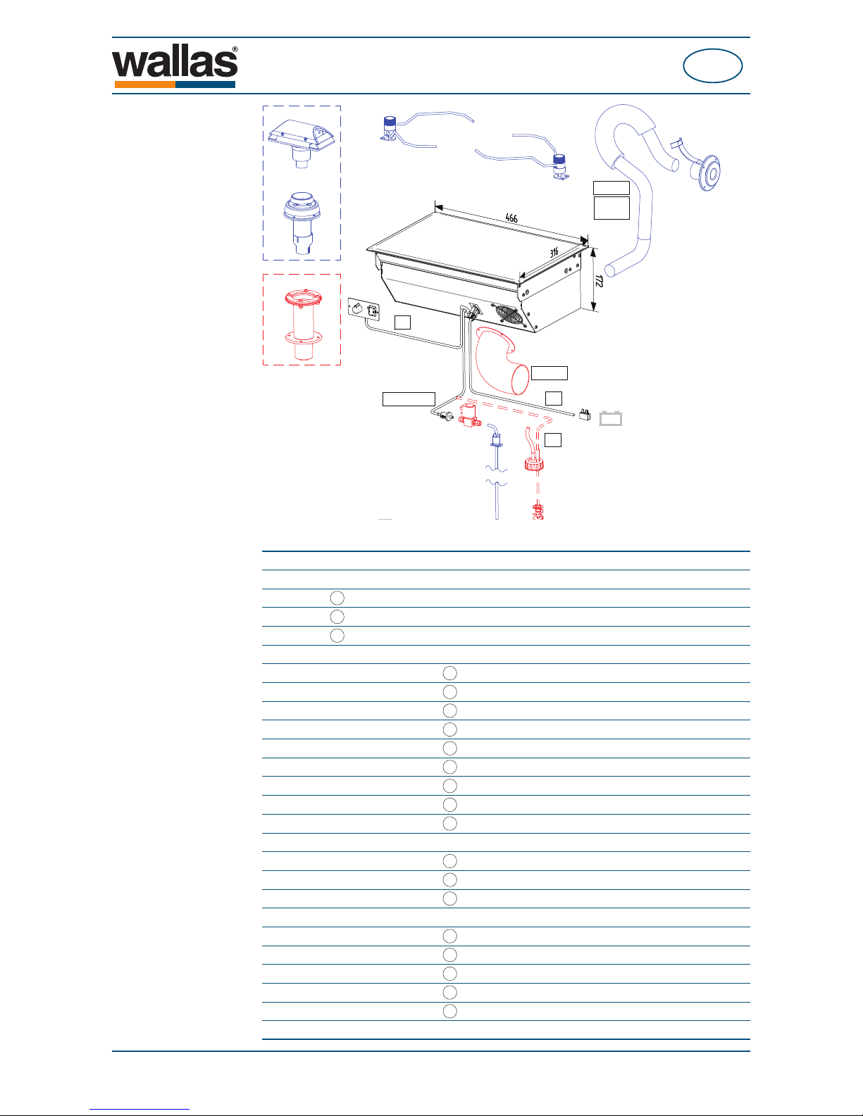
Package contents
2448
2467
3468
2466
30012
30011
367215
O28/45mm
12V
4m, MAX 8m
2m
4m
4m
MAX 2m
2069
3430
MAX 1m
1012
MAX 4m
3430
- 65 -
88DU
Technical information
GB
490070GB
Stove operation
The 88DU is a safe diesel stove with no open fl ame. The stove is equipped with
a single burner which burns either diesel oil or light furnace oil. The stove takes
the air needed for the burning process from the boat and discharges the resultant
smoke with a combustion air blower. This means that, when the stove is being
used, the air in the boat circulates and stays fresh and dry. The steam in the fl ue
gas does not remain in the boat and increase interior humidity.
The fuel pump in the stove dispenses fuel, and the electronics control the combustion air and the amount of fuel automatically to keep the fl ame of the burner clean.
When the stove is switched on, the glow plug in the burner ignites the fuel that has
been pumped into the burner. The glow time is fi xed: it begins and ends automati-
cally.
The heat sensor in the stove detects the heat of the fl ame and lights the red LED
light to signal that the fl ame has been ignited.
The heat which is released as the fuel burns is transferred into the ceramic stove
top. The left side of the stove top is hotter, as the burner is located under it. The
power of the stove can be adjusted steplessly. The control adjusts both sides of the
stove simultaneously.
When the stove is switched off, it cools down automatically. The cooling function
ventilates the burner and discharges the fl ue gases generated during the switch-off
outside the boat.
The stove lends itself extremely well to cooking and warming up all kinds of foods.
It has been manufactured entirely from stainless materials.
Fuel Diesel oil, light furnace oil
12 V DC
0,09 - 0,19 l/h
900 - 1900 W
0.3 A (when ignited ca. 4 min. 8 A)
466 x 316 x 172 mm
ca. 9 kg
2 m (4 m, Intake connection set 3430)
8 m
100 cm
2
2467, 3468 and 2460
1012 Kettle holder set
1150 Toasting grill
3430 Intake connection set
Operating voltage
Consumption
Heating power
Power consumption
Measurements
Weight
Max. permissible length of the fl ue
gas pipe
Max. permissible length of the fuel
hose
Minimum size of the replacement air opening
Suitable fl ue gas lead-throughs
Accessories
Technical information
- 66 -
88DU
Installation
GB
490070GB
Things to note when selecting the installation location
When installing the device, bear in mind that the device must be detached for
maintenance. Therefore, it is advisable to make the connections easy to open and
disconnect.
The stove should be installed level. The inclination must not exceed 5°. While the
device might not break if it is temporarily tilted to a steep angle (even for some
hours), the burner will not yield optimal performance if it is constantly inclined.
Also consider where you will place the control panel, as the length of the control
panel’s cable may pose some limitations.
Avoid installing the control panel in the immediate vicinity of a water outlet.
If possible, install the control panel on a vertical surface.
Moreover, the stove should not be installed on top of a refrigerator. The stove will
heat its surroundings and thus decrease the power of the refrigerator.
We recommend that the device be installed by an authorised Wallas service shop.
Things to note when installing pipes, hoses and cables
Power cables and fuel hoses must be protected in locations where they are susceptible to mechanical damage due to sharp edges or heat.
In a metal-hulled boat, you must ensure that the device, the fl ue gas
lead-through, the fuel connection, the control panel, and all other parts are
insulated from the boat’s hull. This must be done to:
- prevent electrochemical corrosion
- prevent voltage from being transmitted from the hull to the device or vice
versa during electrical faults.
Always use original Wallas accessories and parts with Wallas equipment.
- 67 -
88DU
Installation
GB
490070GB
Stove installation
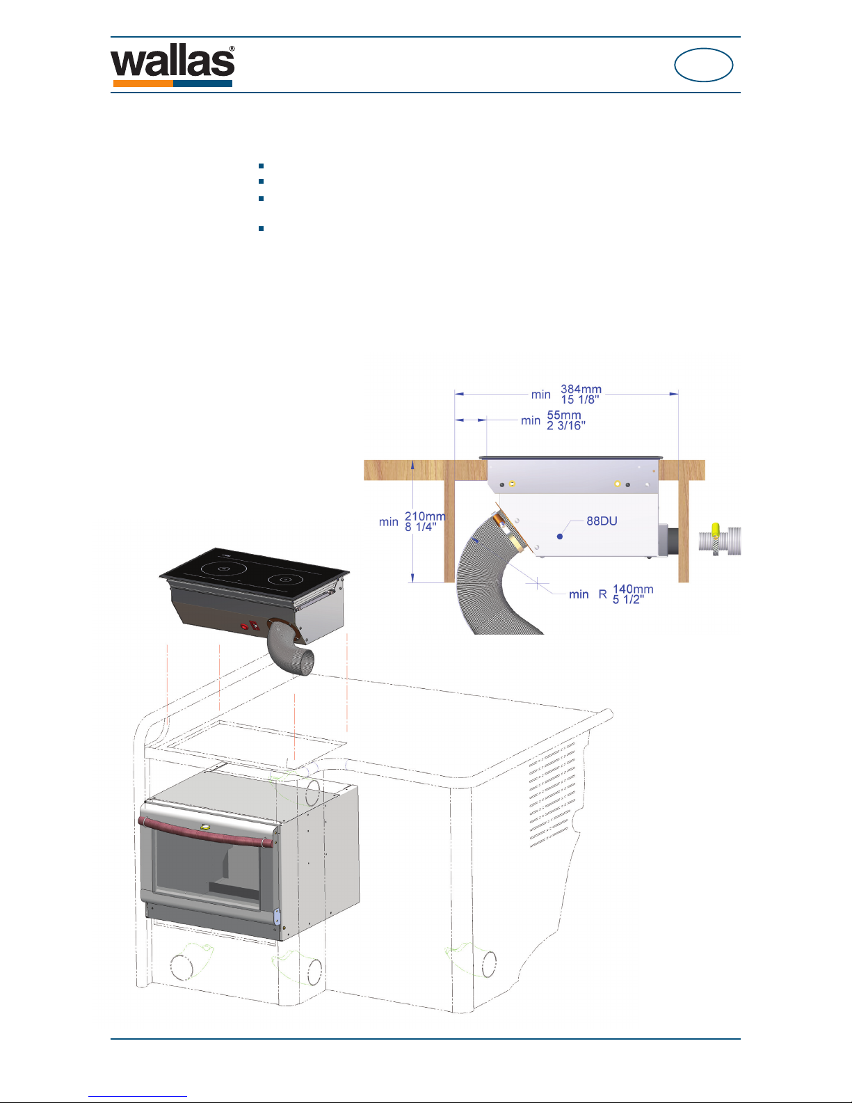
Saw a cut-out (see picture) for the stove and the control panel in your chosen location.
The length of the control panel cable is 2 m.
Measurements of the stove
installation cut-out
Measurements of the control panel installation cut-out
If necessary, predrill holes for the ø 2 mm ( 3/32”) screws.
The stove requires a replacement
air opening of at least 100 cm2.
Ensure that the air circulation under
the stove is suffi cient
Ensure that there is suffi cient space under the
stove for cables and hoses.
The control panel should
be installed on a vertical
surface.
You can also fabricate a
detachable panel to go in
front of the stove. This will
facilitate installation and
maintenance.
442 mm (17 13/32”)
295 mm (11
5
/
8
”)
Ensure that there is suffi cient space
between the stove and the vertical
surface to facilitate installing and
detaching the device.
The control panel
can also be installed
in a vertical position.
7 mm (
9
/32”)
71 mm (2 25/32”)7 mm (9/32”)
35 mm (1
3
/8”)
17,5 mm (
11
/16”)
85 mm (3 11/32”)
- 68 -
88DU
Installation
GB
490070GB
Installing in demanding conditions
If the device is installed or will be used in demanding conditions, e.g.
the fl ue gas hose is 2 to 4 metres long,
the stove is surrounded by thick thermal insulation,
there is another heat source under the stove (e.g. a Wallas oven 86D or a refrigerator),
the climate is particularly warm,
the intake connection set 3430 must be installed on the stove.
Install the set in front of the blower in the stove’s cooling case.
Lead the ø 75 mm hose (max length 1 m) to a location with fresh air. Ensure that
the air fl ows freely into the hose. Do not crimp the hose.
- 69 -
88DU
Installation
GB
490070GB
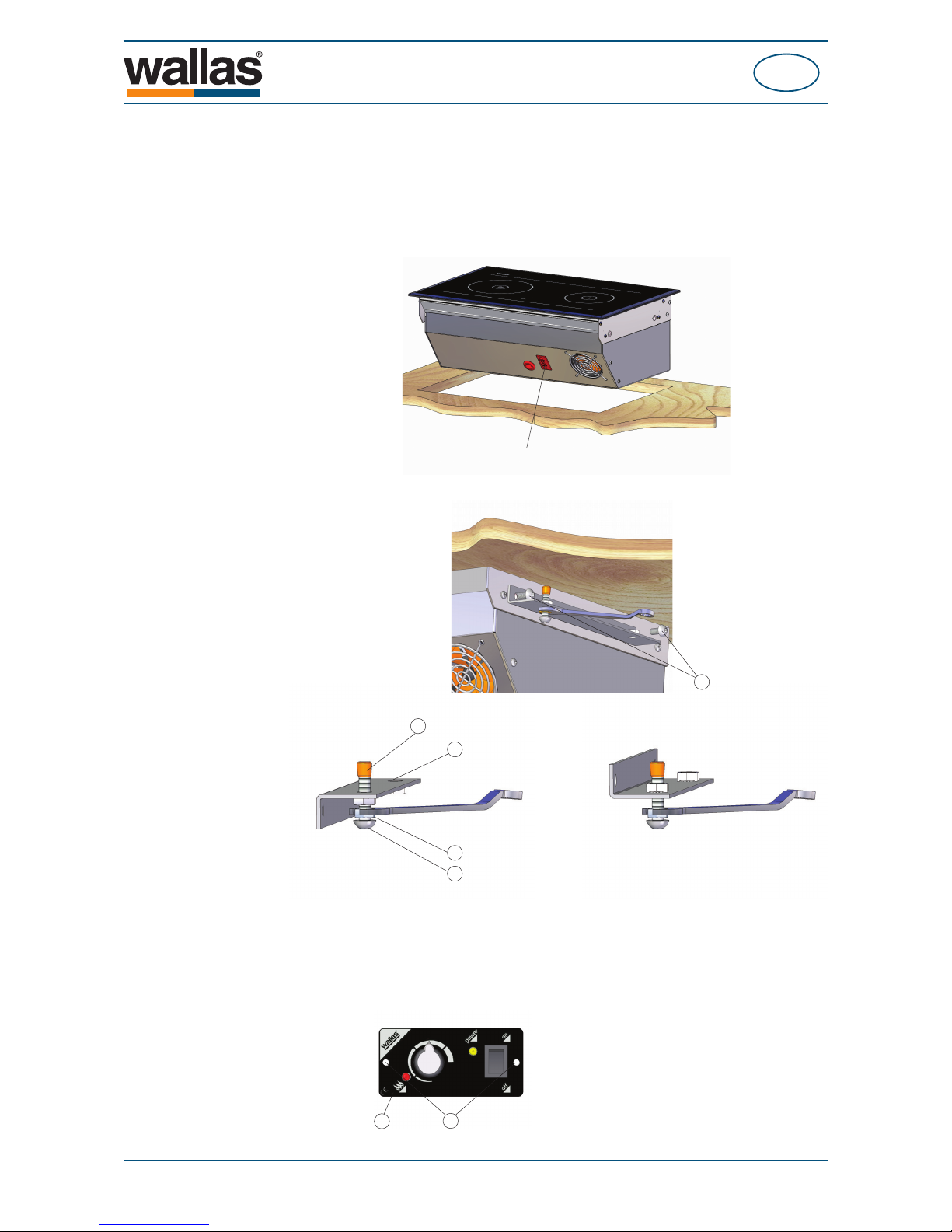
Fastening the device
Place the stove in the installation cut-out and attach the iron fasteners (3) with the
screws (5) to the rivet nuts at the ends. After this, install the cover plug (8) on the
end of the screw and tighten the iron fasteners against the table with the screw (6).
Remember the locking nuts (7).
Use the screws (4) in the accessory bag to fasten the control panel to the table.
1
4
Connect the control panel cable from the
device to the control panel (1).
Use the fastening screws to install the
control panel to the installation cut-out (4).
7
6
3
8
The iron fasteners can be installed in two ways depending on the thickness of the table board.
Push the cover plug (8) on the screw.
Tighten the screw (6) fi rmly against the table board and then tighten the locking nut (7).
Thin table Thick table
5
Attach the iron fasteners to the stove (3) with
screws (5).
Connect the power cord (2) to the connector in the
cooling case of the stove.
- 70 -
88DU
Installation
GB
490070GB
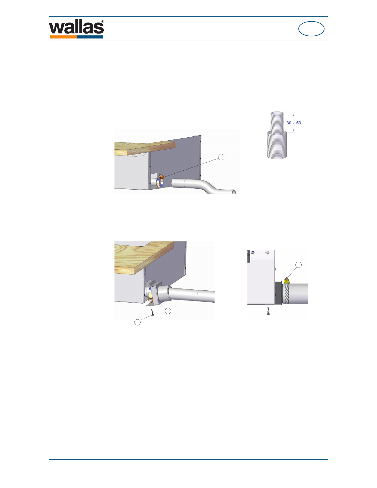
Installation of the fl ue gas pipe
Measure the length of the fl ue gas and exhaust pipe from the device to the gas
lead-through. Remember to add the required length for the swan neck section.
Cut the fl ue gas pipe 30–50 mm longer than the exhaust pipe. This way the pipe
will stay in place in the gas lead-through more fi rmly.
9
15
13
14
Connect the fl ue gas pipe (ø 28 mm) to the device using the
hose binder (9) in the accessory bag.
Attach the connection box of the exhaust pipe (13)
to the cooling case of the stove with a screw (15).
Connect the exhaust (ø 45 mm)
to the connection box with a hose
binder (14).
- 71 -
88DU
Installation
GB
490070GB
Total length of the power cord (m) Cross-sectional are of the cable (mm2)
0 - 4
4 - 6
6 - 10
4
6
10
Table 1.
Main switch
A main switch (accessory) must be installed on the device’s plus cord. Always cut
the power at the main switch, if the device is going to be left unused for a longer
period of time.
ELECTRICAL CONNECTIONS
Things to note about the connections
The device uses 12V direct current voltage. To minimise current losses, make the
power cable as short as possible and avoid jointing. The cross-sectional area of
the cable is dependent on the length of the power cord. See table 1. The crosssectional area of the cable must be consistent all the way from the stove to the
battery. The maximum length of the power cord is 10 m.
Never use the main switch to cut the power before the cooling phase,
which starts after stove is turned off, is completed.
If a thicker cable is required, make a separate joint in the power cord. See picture 1
on the next page.
- 72 -
88DU
Installation
GB
490070GB
Checking the connection
The device consumes most power when it is started up (glowing). At this point
voltage losses are also at their highest. During the glowing phase, the voltage must
be at least 10.7 V measured at the quick coupling. See picture 1. If the voltage is
lower than this, the device may not start.
If you handle an electronics card detached from the device, take care to
avoid damage due to static electricity.
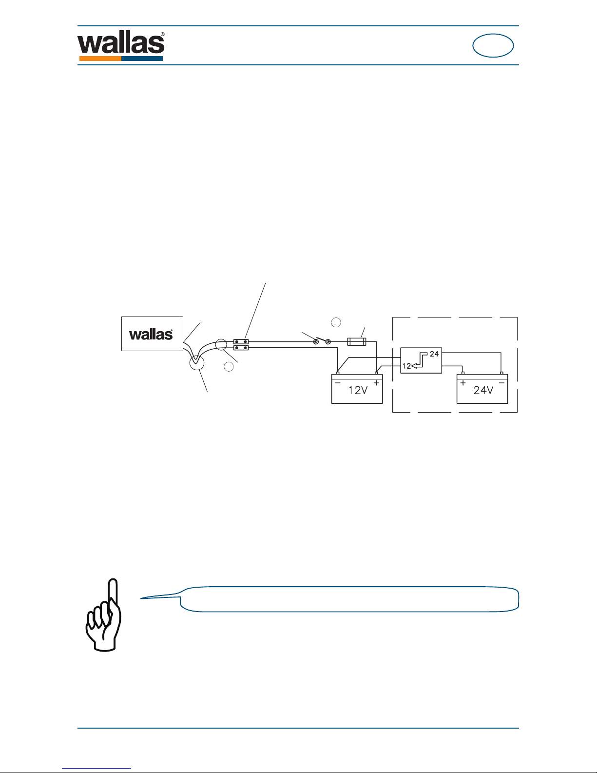
Picture 1.
24V direct current system
Dewatering loop
If the cables will be above the stove, a
dewatering loop is required. This prevents
condensated water from running to the
circuit board.
Device’s quick
coupling
Jointing
A jointing should only be made in long
power cords, if necessary, in which case
the cord must be replaced with a thicker
one. The jointing cannot be further than 1
meter from the device.
Main switch
Main fuse
Power cord
2
13
Electrical connections of the device
12V direct current system
Connect the red wire of the power cord to the plus terminal of the battery and the
black or blue wire to the minus terminal. A 15 A main fuse must be installed near
the battery on the red plus wire of the power cord. See picture 1.
24V direct current system
If the device is to receive power from a 24V system, always connect a charging
voltage reducer and a 12V battery before connecting the device. Without the battery the voltage reducer will not be enough on its own as it cannot generate the
large amount of current the glow plug requires. After the 12V battery, the connection is the same as in a 12 V system.
- 73 -

88DU
Installation
GB
490070GB
FUEL CONNECTIONS
Things to note about the connections
The standard length of the fuel hose is 4 m (max 8 m). Cut the fuel hose to a length
suitable for installation.
The lift height of the pump should be less than 2 m; preferably 0.5 – 1 m.
The fuel pipe must always have a fi lter. The fuel fi lter can be installed either near
the device, near the tank, or in another location where it can be easily checked and
replaced, when necessary.
All connections should be made with rubber or silicone hose which is resistant to
diesel.
Country-specifi c requirements
The standard fuel hose is plastic. Please observe country-specifi c requirements
with regard to the material of the fuel hose/pipe and the fuel fi lter. The inner diam-
eter of a new replacement hose must be equal to the inner diameter of the plastic
hose.
Copper pipe and metal fi lters are available as accessories.
The fuel connections must be tightened fi rmly so as to not allow air to
leak into the hose. Always check the cleanliness of the connection surfaces before tightening.
Air will cause the device to malfunction.
Fuel feed
If the lift height is outside the recommended 0.5 – 1 m, the fuel feed must be
checked and, if necessary, adjusted. The fuel feed must also always be checked,
if parts of the fuel system, such as the pump or the electronics card, have been
replaced.
Fuel system adjustments are device specifi c. We recommend that the adjustment
be carried out by an authorised service shop.
Optimal fuel tank
location
TANK
TANK
MAXIMUM
OPTIMUM
0,5 m
1 m
2 m
Checking /
adjustment
Checking /
adjustment
TANK
- 74 -
 Loading...