

wallas 85DU w/270 Lid, 85DP w/270 Lid Installation And Start-up Manual
INITIAL INSTALLATION AND START-UP TIPS
WALLAS 85 DU & DP COOKTOP
The 85 series Wallas cook-top is the third generation of cooking devices
from this Finnish compa ny. Starting in 1995, Wallas introduced a #2 diesel
fueled cook-top called the Model 95D, designed primarily for the North
American market. This model was manufactured through 2005.
Though primarily intended for “recreational” use, many 95Ds were placed
into “commercial” use, with reasonable success, and most units,
recreational and commercial, are still in service today. Most 95Ds sold
here in North America were fitted with the model 25 blower lid, that
combination of stove and lid was marketed as the 125D. Early 25 lids had
a wood veneer top, while the later 25E models had a tooled metal top.
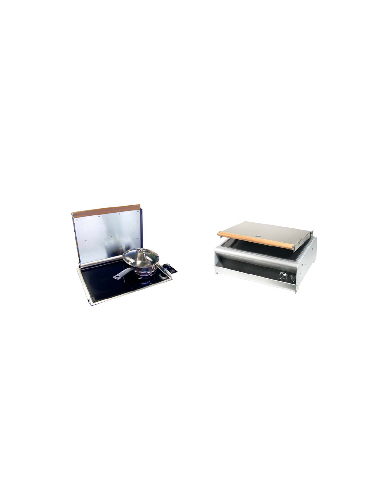
85DU w/270 Lid
In 2006, the current Model 85 started into production. This model grew out
of the information received from nearly 10,000 Model 95D’s sold
throughout the world. Some of the major improvements in the model 85D
over the model 95D include a dramatically strengthened “case” with a
“bonded” ceramic surface, a highly refined PC board with internal hour
meter, and super long life “brushless” motors for combustion and heating.
As of 2011, over 8,000 of these 85D units have been sold and have proven
to have a very robust design and a significantly longer service interval
than the Model 95D. Blower and combustion fan life is many times that of
the 95D.
85DP w/270 Lid

In most cases the 85D has been sold in North America fitted with the 270
blower lid, a significant improvement over the 25 lid, with variable blower
speed to match combustion power level. Both the 95 and 85 have been
made available in DU (flush mounted) and DP (countertop mounted)
versions. The DP models are essentially DU models mounted in an
aluminum enclosure that can sit on top of a counter or table.
TIPS TO INSURE SUCCESSFUL INSTALLATION
In addition to the instructions supplied with your model 85D, please follow
these easy, extra steps during your installation.
PRIOR TO INSTALLATION
1. Please assemble this short list of tools and keep them handy for
installation and future repairs and maintenance:
(1) 12mm end wrench;
(1) #2 Phillips driver;
(1) 1/8” blade slot driver;
(1) small adjustable wrench or vise grip.
2. Take the time to verify that ALL electrical connections on the
underside of the cook-top are secure and tight. The units are
manufactured in Finland and have traveled many miles and
handled many times before your purchase. Things can, and often
do “get loose.”
3. Make sure the two set screws holding the white “male” plug on the
main power wires are tight
4. On units built prior to 2008, the small black plug from the lid blower
assembly must be oriented correctly and inserted fully until it “clicks”
into position in the back of the stove section. The small clip that
holds the power cord securely into the receptacle is always in the
DOWN position. Lids built in 2008 and later do not use this cord and
plug, the lid being captive to the lower assembly (lid not
removable).

AFTER INSTALLATION AND BEFORE START-UP
1. Make sure the black connect cable from the controller to the front
of the cook-top under the counter on the DU model, “clicks” into
position on both the controller and the cook-top.
2. Make sure the red and black power cable with the white plug is
fully inserted into the white receptacle on the back side of the
cook-top under the ceramic.
3. VERY IMPORTANT! The fuel line to fuel pump connection under the
cook-top is critical for proper starting and running of the Wallas 85.
The fuel line fitting is a well designed part and must be assembled
and installed correctly. IF THERE IS EVEN A TINY AIR LEAK AT THIS
CONNECTION, THE UNIT MAY NOT START OR RUN PROPERLY.
4. If assembling a new crimp on fuel fitting, make sure the tiny internal
tube support is fully inserted into the clear plastic fuel line. Slide the
compression nut onto the fuel line, be sure the ferrule is flush with
the end of the plastic fuel line, and then CAREFULLY pre-crimp the
assembly, by fastening the fitting assembly onto the fuel pump
elbow. Remove the fitting and examine the crimp. If satisfied,
retighten the fitting WITH TWO WRENCHES. This connection must be
TIGHT.
INITIAL START-UP
The control panel is dual purpose. It controls the start-up and heat output
of the cook top and it serves as a diagnostic tool. This second purpose is
particularly valuable if the unit will not start. On the panel are two LED
lights. The right side “yellow” light verifies the power supply, and the left
side “red” light verifies that ignition is complete and the unit is starting to
warm up. If either or both lights are blinking there is a problem you need
to solve. This diagnostic feature is described on page 13 in the owner’s
manual. We recommend you copy this page, have it laminated, and
keep in on the boat. Here is an additional description of the “light
messages” you eventually see:
 Loading...