

wallas 2400 t, 1800 t Installation Manual
10L
5L
2413
2411
2410
2412
2467
2448
2460
28/45mm
MAX 2m
1800,
MAX 5m
6m
6,2
kg
60
1,55m
7
kg
1800
2400
3415
12V
2400,
MAX 8m
2069
- 67 -
1800 t / 2400 t
1
2
3
4
5
7
8
9
10
12
6
11
13
en
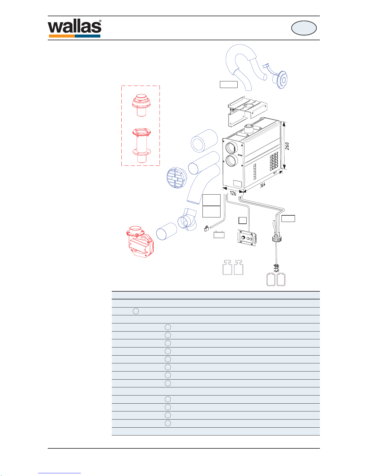
Technical information
Mounting bolt M8 x 120 mm DIN 931 / ISO 4014
Corrugated base plate M8 DIN 137 A
Hose binder 32 - 50 mm
Fuse box
2 pcs
2 pcs
1 pcs
1 pcs
Heater (fuel hose and control panel cable installed)
Accessory bag 17662B
Mounting plate
1 pcs
1 pcs
1 pcs
1 pcs
2 pcs Push on contact 6.3 x 0.8 (yellow)
Fuse 15 A (blue)
Fastening screw 4,8 x 16 mm DIN 7981 / ISO 70496 pcs
Installation, operation and maintenance instructions1 pcs
Control panel
Control panel fastening screws 3,5 x 20 mm (black) TX10
Control panel package 3610661 pcs
1 pcs
4 pcs
Hose binder 50 - 70 mm2 pcs
Extension collar1 pcs
Control panel fastening screws 3,5 x 40 mm (black) TX104 pcs
Package contents
1800 t / 2400 t
490535
en

- 68 -
12 V DC
1800 t 2400 t
0,35 - 0,5 A 0,6 - 1,0 A
0,10 - 0,18 l/h 0,12 - 0,23 l/h
900 W 1100 W
1700 W 2200 W
2 x ø 60 mm
en
Technical information
Fuel Paraffi n
6,2 kg
13,7 lbs
Operating voltage
Fuel consumption
Heating power, max
Power consumption
Dimensions (L x H x W)
Weight
Maximum permitted length of
exhaust pipe
Maximum permitted length of
fuel hose
Minimum area of the replacement air
opening
Suitable Exhaust gas lead-throughs
Technical information
2467 and 2460
Heating power, min
Maximum permitted length of
warm air duct
Warm air connection
Remote control
Timer
Connections
364 x 260 x 126 mm
14 3/8“ x 10 1/4” x 5”
8 m
26’
100 cm
2
16 square inches
8 + 8 m
26’ + 26’
2 m (ø 28/45 mm)
6,5’ (ø 28/45 mm)
5 + 5 m
16’ + 16’
7 kg
15,4 lbs
(when ignited ca. 2 min. 5 A)
1800 t / 2400 t
490535
en
- 69 -
en
Installation
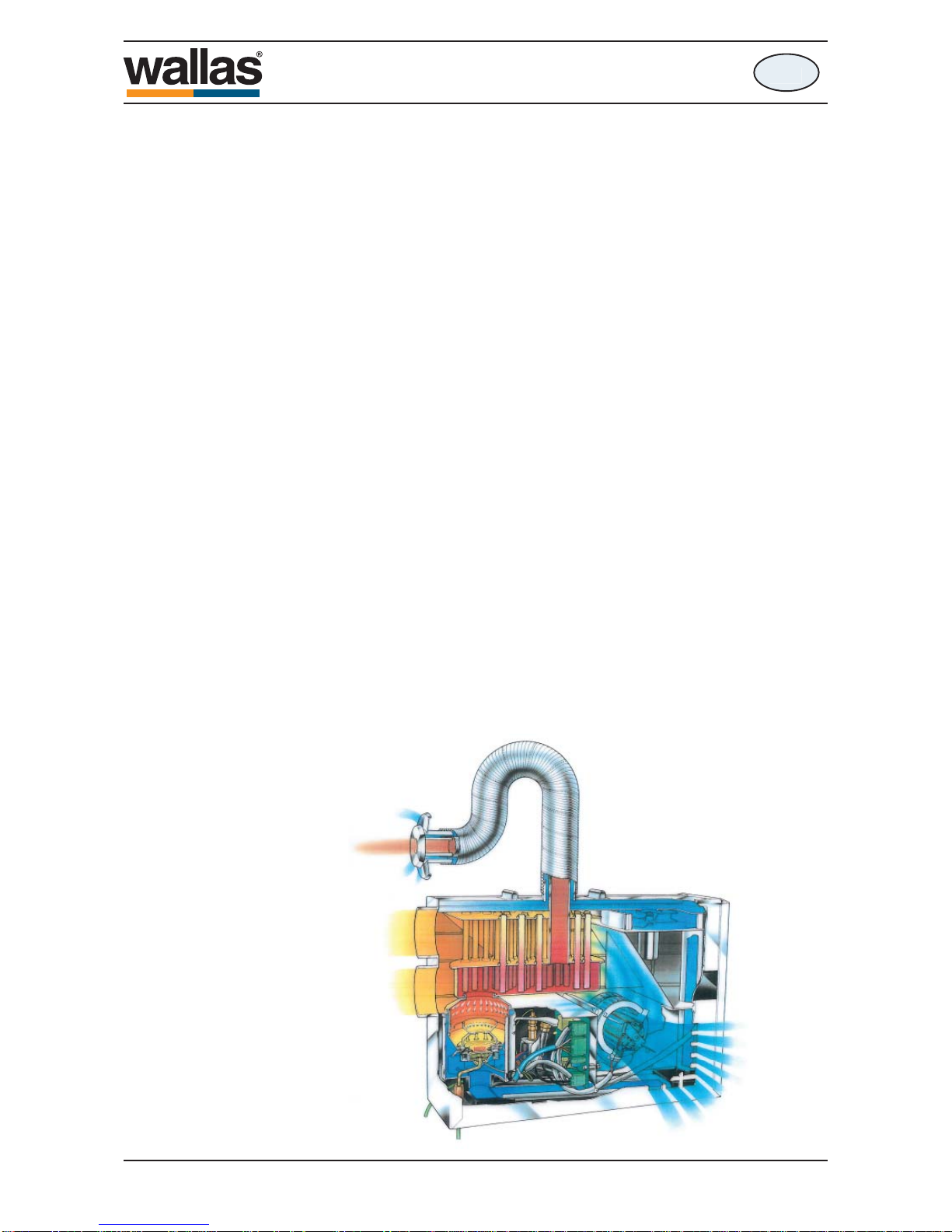
Operation description
The 1800 t and 2400 t heaters are forced air diesel heaters without an exposed
flame.
The 1800 t and 2400 t models take combustion air from outside the boat through
the outer coaxial exhaust gas pipe and blow their exhaust out through the inner
coaxial pipe. The coaxial pipe connects to a common through hull fi tting that allows
both inlet air and exhaust to pass separately. This process improves effi ciency ,
wind resistance and lowers the minimum power level.
The heat generated by forced air fuel combustion, is transferred to the circulation
air by a heat exchanger. The heating power can be adjusted freely between high
and low output settings by manual rheostat control or by thermostat.
The heated air is circulated through the cabin through the warm air ducting.
In hot and/or humid conditions, these heating units can be used for simple fresh air
ventilation and circulation.
When starting the device, the glow plug ignites the pumped fuel in the burner bowl.
The glow/start and shut down sequences are factory programmed, so - starts and
stops are automatically controlled.
The fuel pump inside the heater case regulates the fuel feed and the system
electronics control both the fuel and air mixture to maintain the ideal clean burning
process. The temperature sensor inside the burner feels the ignition and lights up
the red signal light (1) to indicate a successful start. When stopping the device, an
automatic after cooling process takes place. This process cleans the burner, purging any unburned fuel.
The heaters are completely made out of corrosion resistant materials.
1800 t / 2400 t
490535
en
- 70 -
en
Installation
Heater installation
Country specific regulations shall be followed in any installation.
The warranty of boat products is valid only in boat installations.
The warranty is not valid in installations to vehicles or other spaces.
The device is meant for marine pleasure craft use. The device is not designed for
continuous use for example in live aboard boats or commercial settings. In such
use the device will require more frequent servicing not covered by warranty.
Things to note when selecting the installation location
The device shall be installed into a dry space in a protected location.
The device must be mounted to a solid, stable bulkhead or wall.
When installing, please note that the device needs to be removable for servicing.
Connections and location should be made so that the device can be easily disconnected for removal. For maintenance, it is useful to leave 200 mm (7 7/8”) empty
space below the heater for the removal of the bottom cover of the heater.
The heater should be installed vertically level when the boat is on an even keel.
The static inclination must not exceed 5°. While the device will tolerate being
temporarily tilted to a steep angle (even for some hours), the burner will not yield
optimal performance if it is constantly inclined.
Please note specially the following things:
• Avoid installing the control panel in the immediate vicinity of a water outlet.
• If possible, install the control panel on a vertical surface.
• Select the place of installation to allow a minimum amount of bending in the
warm air ducting.
We recommend that the device be installed by an authorized Wallas service shop
or installer.
Things to note when installing pipes, hoses and cables
Power cables, warm-air ducting and fuel hoses must be protected in locations
where they are susceptible to mechanical damage due to sharp edges or heat.
All cables and hoses should have a fl uid precluding “drip loop” to prevent water or
other fl uids from following wires or hoses to the heater.
Installation space
The device can be installed within the heated space or outside of it.
The heater cannot be installed into a space which may include
gasoline fumes (danger for explosion).
1800 t / 2400 t
490535
en
- 71 -
13 mm
ø 35 / ø 50 mm
ø 60 mm
ø 67 mm
ø 2 mm
ø 5 / ø 6 mm
PZ 2
PH 2
TX 10
en
Installation
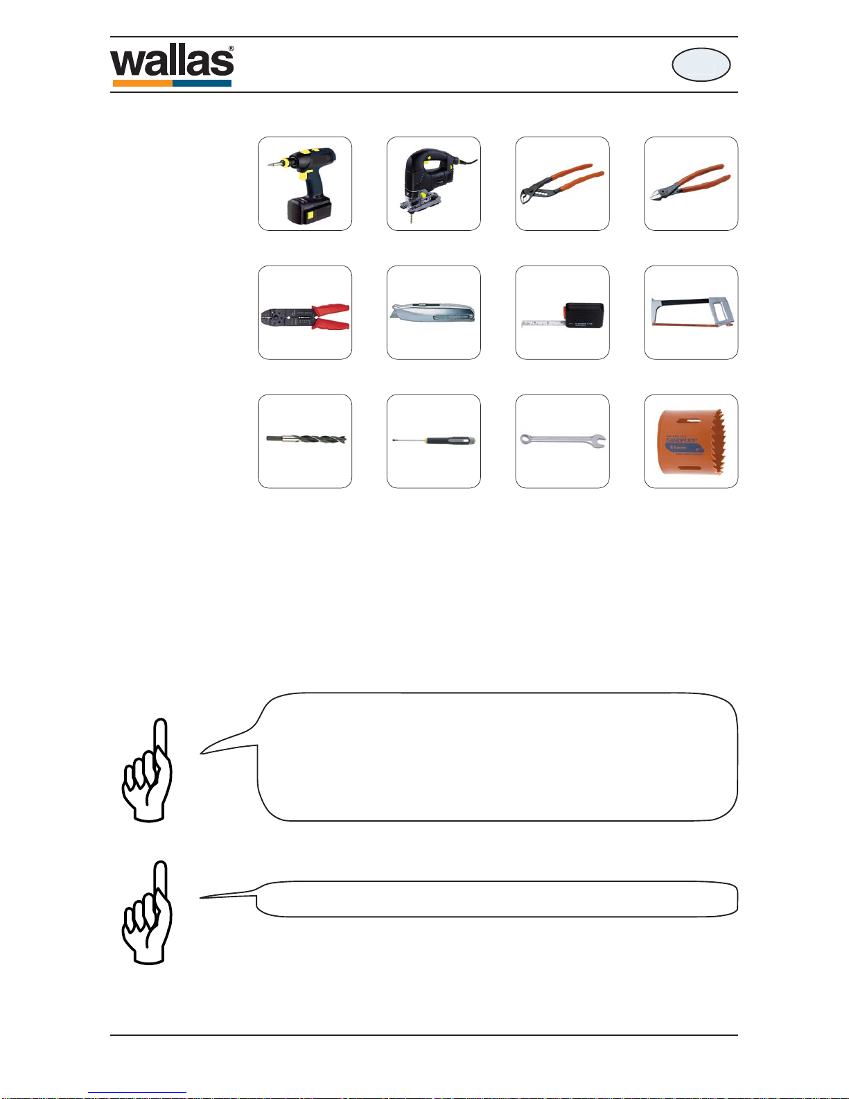
The necessary installation tools
Always use original Wallas accessories and parts with Wallas
equipment.
In a metal-hulled boat, you must ensure that the device, the exhaust
gas lead-through, the fuel connection, the control panel, and all other
parts are insulated from the boat’s hull. This must be done to
• prevent electrochemical corrosion
• prevent voltage from being transmitted from the hull to the device
or vice versa during electrical faults.
1800 t / 2400 t
490535
en
K00038
K00101
- 72 -
1
5
23
4
en
Installation
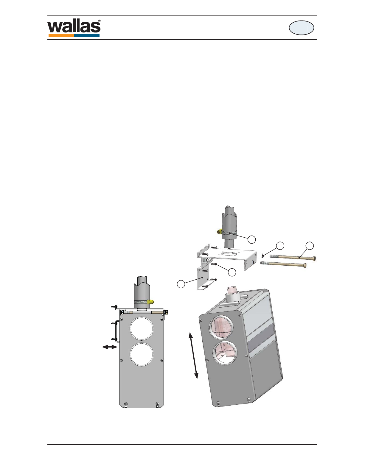
Fastening the device
Fix the mounting plate (1) with screws (4) to a suitable place and check that the
bottom of the heater is in horizontal position.
Lift the heater into the installation plate and lock the device with the mounting bolts
(2). There has to be a corrugated base plate (3) under the head of the screw. Be
sure that the edge of the mounting plate will lock to the slot in the side profi le of the
heater.
Connect the exhaust gas pipe with a hose clamp (5).
1800 t / 2400 t
490535
en
- 73 -
X
311 mm
125 mm
381 mm
70 mm
1k
1
43
2
43
45
42
47
44
43
41
3
2
1
J
40
J
47
40
44
45
43
1k
3
42
en
Installation
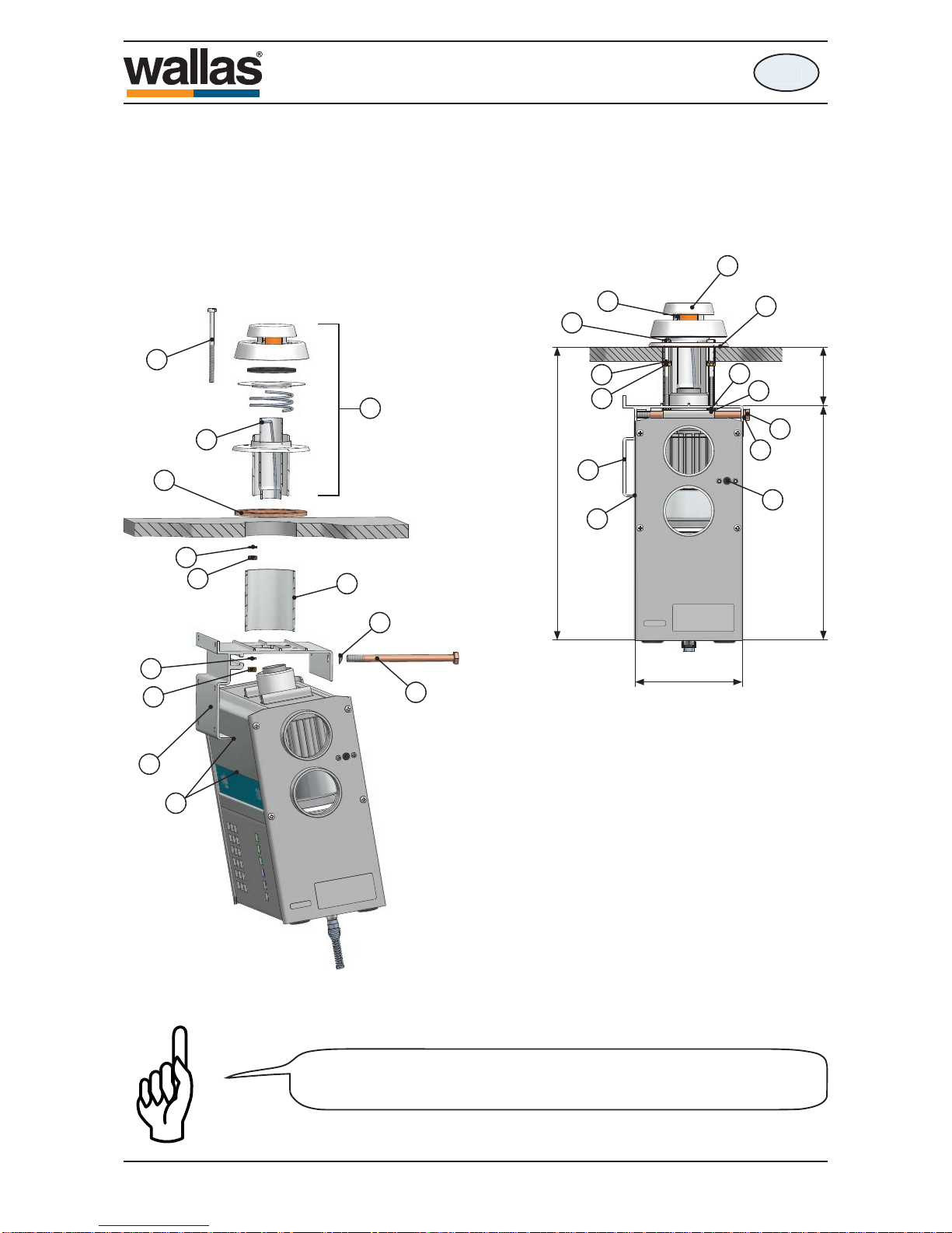
Direct attachement to exhaust on deck
• Exhaust head 2460 closes by pressing down and turning clockwise, opens by
turning counterlockwise.
• Exhaust head is opened for mounting by pressing in the pin (J) with screwdriver etc. from outside.
• Gasket (47). Important that the gasket surfaces and the take through hole are
carefully sealed with silicone seal.
• The exhaust head is mounted on deck with bolts
(42) M5 x 85 and nuts (43) with lock washer (44)
under. Tight the nuts, but not so hard the base
plate deforms.
• Place the spacing tube (41) and mounting plate
(1) on bolts (42) and fasten with nuts (43) with
lock washer (44) under. Tight the nuts, but not so
hard the exhaust base plate deforms.
• Check and retight the nuts (43).
• Place the heater on mounting plate (1). The cant
(1k) helps to hold up the heater. Check that the
heater exhaust pipe goes well in the exhaust head
middle pipe.
• Fasten the heater on mounting plate (1) with bolts
(2) M8 x 120 mm and tight them..
Check that the heater is mounted so that the overheating cut-out reset
buttom (X) is accessible for hand.
1800 t / 2400 t
490535
en
K00114
- 74 -
ø 2 mm (3/32’’)
100 mm (3
15
/16’’)
65 mm (2 9/16’’)
17,5 mm
(
11
/16’’)
4,5 mm (
11
/64’’)
47 mm (1
27
/
32
’’)
56,1 mm (2
13
/
64
’’)
10 12
17,5 mm
(11/16’’)
69 mm (2
23
/
32
’’)
104 mm (4 3/32’’)
en
Installation
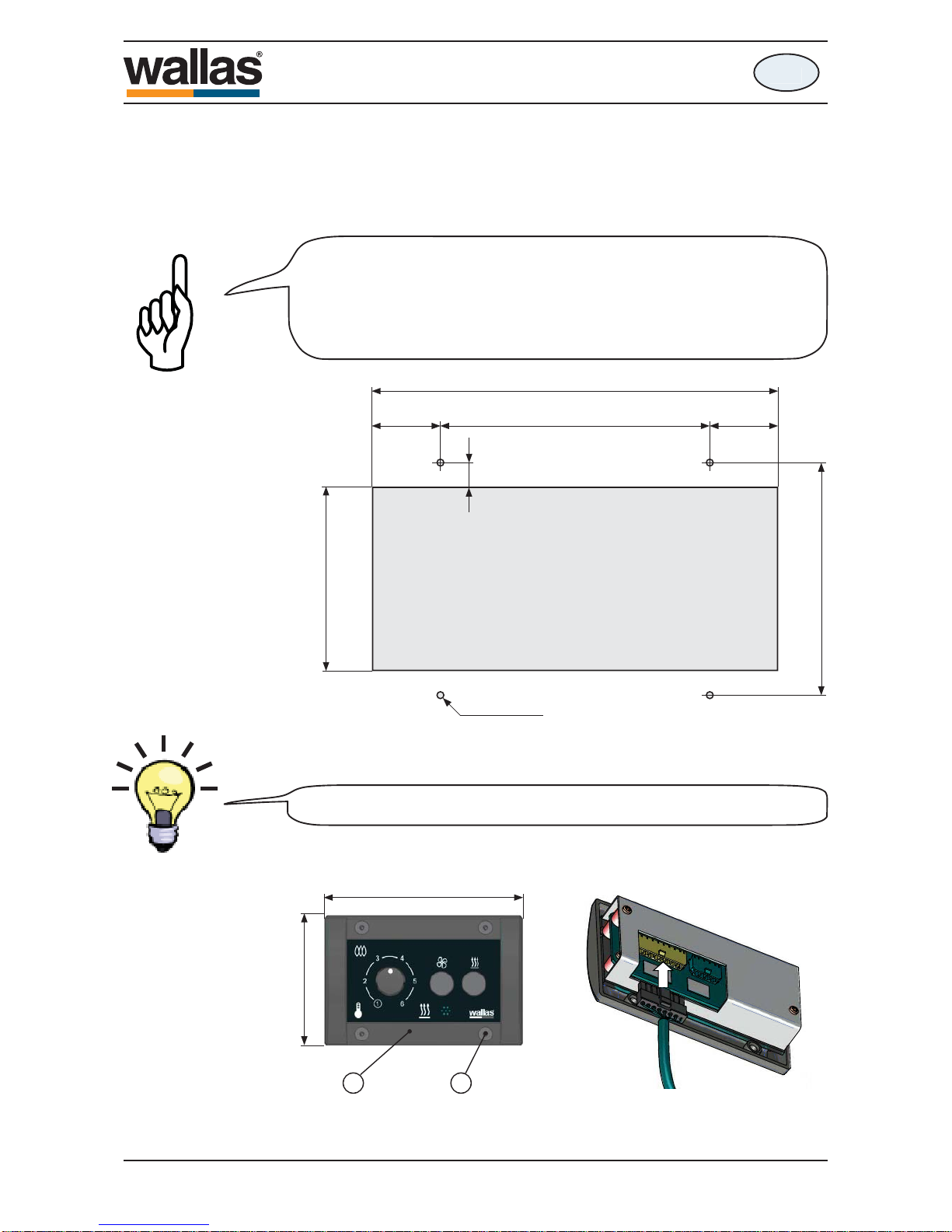
Control panel installation
Cut a suitable installation hole for the control panel in the selected location. Try to
install the panel in a vertical surface in a location that will remain dry.
Measurements of the control panel installation cut-out.
If necessary, predrill holes for the ø 2 mm ( 3/32”) screws.
You can utilize the sample of the box when drawing the lines of the
installation hole.
Connect the control panel cable from the device to the control panel (10).
Use the fastening screws to install the control panel to the installation cut-out (12).
The thermostat sensor is in the panel face, so select the location
with thermostatic operation/regulation in mind. Do not install close
to heat source or close to a window or door. Avoid locations that
might be contacted by direct sunlight. The length of the control
panel cable is 6 m.
1800 t / 2400 t
490535
en
K00143
- 75 -
11
13
en
Installation
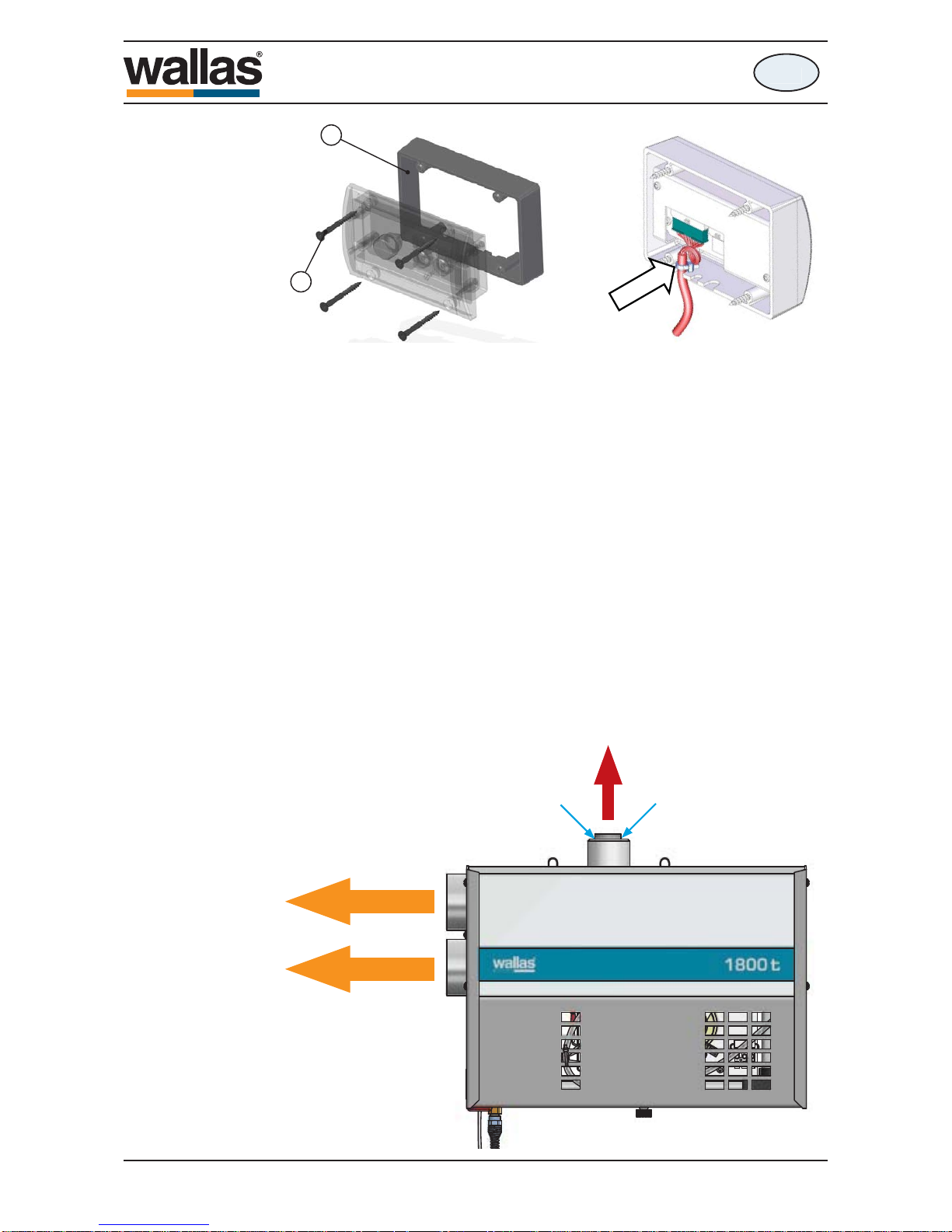
An extension collar (11) is used when control
panel is surface mounted.
The box of the panel includes 4 pcs screws 3,5
x 40mm (black) TX10 (13).
When installing the control panel surface
mounted (using the collar) , a loop to the
control panel cabel must be done. A cable
tie must be attached to cable in order to
avoid the cable detach from the connector.
Connections of the device
Things to note about the connections
In installation, to make the mounting and demounting for service easier, it is recommended to leave some extra length of loose cables and fuel line by creating a coil.
WARM AIR
OUT
EXHAUST
OUT
COMBUSTION AIR
IN
1800 t / 2400 t
490535
en
 Loading...