

Wallace International Kinetic DC 15W, Kinetic DC 10FW Installation And Maintenance Manual

Wallace International
Kinetic DC 15W Gate Operator
Kinetic DCS 15W Gate Operator
Kinetic DC 10FW Gate Operator
Kinetic DCS 10FW Gate Operator
Installation and Maintenance Manual
Wallace International
90 Lowson Cr.
Winnipeg, Manitoba. R3P 2H8

Contents
Introducing Kinetic DC
KINETIC COMPONENTS ....................................................................................................................................... INTRO-1
INTELLIGENT FEATURES SMART DC CONTROLLER™ .......................................................................... INTRO-2
TECHNICAL SUPPORT ............................................................................................................................................... INTRO-3
INSTALLER’S CHECK LIST ....................................................................................................................................... INTRO-4
Chapter: Safety Requirements
IMPORTANT SAFETY INSTRUCTIONS ........................................................................................................................... S-1
Safety Standards – Installer’s Responsibility ....................................................................................................... S-1
Safety Standards – Owner / User Responsibility
Hazardous Materials and Proper Disposal .......................................................................................................... S-4
SECONDARY ENTRAPMENT PROTECTION SENSORS .......................................................................................... S-5
Identifying Gate Operator and Usage Class ........................................................................................................ S-6
Choosing Secondary Entrapment Protection .................................................................................................... S-7
EMERGENCY STOP BUTTON ............................................................................................................................................. S-8
EMERGENCY RELEASE ......................................................................................................................................................... S-8
SAFETY NOTICES ..................................................................................................................................................................... S-9
.............................................................................................. S-3
Chapter 1: Installation
SITE OVERVIEW & PLANNING ........................................................................................................................................ 1-1
INSTALLING THE DRIVE AND TOOTHRACK ............................................................................................................ 1-2
Installing the Kinetic Operator on Gate Post .................................................................................................... 1-2
Adjusting Drive Height ................................................................................................................................................. 1-3
Adjusting Spur Gear Alignment ............................................................................................................................... 1-3
Installing Toothrack
Connecting the Battery and Turning DC Power ON .................................................................................... 1-5
Programming the Initial Setup Menu
Establishing OPEN & CLOSE Limits
Installing the Target Magnet ....................................................................................................................................... 1-8
....................................................................................................................................................... 1-4
..................................................................................................................... 1-6
................................................................................................................. 1-7
Chapter 2: Power
INSTALLING THE EARTH GROUND .............................................................................................................................. 2-1
W
IRING THE AC POWER .................................................................................................................................................... 2-3
Wiring 115VAC Power
Wiring 230VAC Power ................................................................................................................................................. 2-5
................................................................................................................................................. 2-4
Rev: A Contents-1

Contents
USING A SOLAR POWERED OPERATOR ...................................................................................................................... 2-6
Design Requirements & Considerations .............................................................................................................. 2-6
Connecting the Kinetic DCS to Solar Power
Connecting Peripherals Solar Operators
.................................................................................................... 2-7
.............................................................................................................. 2-8
Understanding Gate Activity Based on Solar Zones ..................................................................................... 2-9
IMPORTANT CONSIDERATION FOR DC POWERED OPERATORS ...............................................................2-10
Installing the Extended Battery Backup Kit .................................................................................................... 2-11
Chapter 3: Display and Menu Options
INITIAL SETUP ........................................................................................................................................................................... 3-1
Turning Both Power Switches On
Using Smart DC Controller Buttons in MENU Mode ................................................................................. 3-3
RUN MODE ................................................................................................................................................................................. 3-4
Understanding Gate Status Displays ..................................................................................................................... 3-4
Using Smart DC Controller Buttons in RUN Mode .................................................................................... 3-5
Viewing Operator Status Displays ......................................................................................................................... 3-6
USER MENU .............................................................................................................................................................................. 3-7
Adjusting the Closer Timer ....................................................................................................................................... 3-8
Setting the Time & Date ............................................................................................................................................. 3-9
Setting AC Power Loss Gate Function .............................................................................................................. 3-10
Adjusting the Display Contrast .............................................................................................................................. 3-11
INSTALLER MENU ................................................................................................................................................................ 3-15
Resetting the OPEN & CLOSE Limits ............................................................................................................ 3-16
Adjusting Gate Speed ................................................................................................................................................. 3-17
Adjusting IES Sensitivity ........................................................................................................................................... 3-18
Reinstating the Factory Defaults
Enabling the Fire Department Override ........................................................................................................... 3-21
.......................................................................................................................... 3-2
........................................................................................................................... 3-20
Chapter 4: Smart DC Controller
OVERVIEW OF THE SMART DC CONTROLLER ....................................................................................................... 4-2
V
EHICLE DETECTOR INSTALLATION OPTIONS ................................................................................................... 4-4
Using Connecting the HY-5A Vehicle Detectors
Installing Standard 11-Pin Box Type Vehicle Detectors
Vehicle Detectors Configuration and Quick Close Mode Selection .................................................... 4-8
ONNECTING ACCESSORY DEVICES ......................................................................................................................... 4-9
C
Entrapment Sensor Connections
Manual Push Button Station .................................................................................................................................... 4-10
User Relays – Programming Procedure
Contents-2 Rev: A
.......................................................................................... 4-5
............................................................................ 4-7
........................................................................................................................... 4-9
............................................................................................................. 4-11

Contents
Chapter 5: Bi-parting Gate Systems
POWER REQUIREMENTS ..................................................................................................................................................... 5-1
MASTER & SLAVE WIRING CONNECTIONS .............................................................................................................. 5-2
MASTER & SLAVE MENU SETUP ..................................................................................................................................... 5-3
Chapter 6: Reference
CONNECTING A RADIO RECIEVER FOR REMOTE OPEN ................................................................................. 6-1
INSTALLING A MAGLOCK OR SOLENOID LOCK .................................................................................................. 6-2
Installing a Lock for 12VDC or 24VDC Systems .......................................................................................... 6-3
Installing a Lock for 12VAC Systems .................................................................................................................. 6-4
Installing a Lock for High Voltage Systems
Setting the User Relay Function in the Installer Menu
INSTALLING VEHICLE DETECTORS AND LOOPS ................................................................................................. 6-6
INSTALLING PHOTOELECTRIC SENSORS, SECONDARY ENTRAPMENT PROTECTION ONLY .... 6-9
Operation Notes .............................................................................................................................................................. 6-9
Supervised Connection ............................................................................................................................................... 6-11
Photoeye Function ........................................................................................................................................................ 6-11
USING PHOTOELECTRIC SENSORS INSTEAD OF VEHICLE LOOPS .......................................................... 6-12
INSTALLING GATE EDGE SENSORS .......................................................................................................................... 6-14
SMART DC CONTROLLER TROUBLESHOOTING ................................................................................................ 6-15
Vehicle Detector and Loop Fault Diagnostics ............................................................................................... 6-22
Kinetic Schematics ................................................................................................................................................. 6-24
GENERAL MAINTAINANCE ............................................................................................................................................. 6-26
Smart Touch Analyze and Retrieve Tool .......................................................................................................... 6-26
What You Need ................................................................................................................................................. 6-26
Installing START Software .......................................................................................................................... 6-26
Setting User Account Controls .................................................................................................................. 6-27
Electrical Controls
Mechanical Maintenance ............................................................................................................................................ 6-28
Software Maintenance ................................................................................................................................................. 6-28
Drive Belt Tension and Alignment
DC Battery Replacement
Clock Battery Replacement
........................................................................................................................................................ 6-27
............................................................................................................................... 6-30
.......................................................................................................................... 6-32
...................................................................................................... 6-4
............................................................................... 6-5
.......................................................................................................... 6-29
Parts & Limited Warranty
LIMITED WARRANTY ..........................................................................................................................................................
KINETIC DC SPECIFICATIONS ..............................................................................................................................
Rev: A Contents-3

PRODUCT & WARRANTY REGISTRATION
Enter the following information to register your Wallace product. Please write legibly. Today’s Date:_____________________
NOTE: To extend the operator warranty beyond 1 year, you must return this registration within 60 days of purchase. Refer to the Limited Warranty.
Installer Information
First/Last Name: _________________________________________
Company Name: _________________________________________
Address: _______________________________________________
City: ____________________________ State/Province: __________
Country: _______________________ Zip/Postal Code: _________
Daytime Phone: ___________________ Fax: __________________
E-mail: _________________________________________________
End-user Information
First/Last Name: _________________________________________
Company/Association: ____________________________________
Address: _______________________________________________
City: ____________________________ State/Province: __________
Country: _______________________ Zip/Postal Code: _________
Daytime Phone: ___________________ Fax: __________________
Product Information
Model name/number: ______________________________________
Serial number: ___________________________________________
Purchase Date: __________________________________________
Purchase Price: __________________________________________
Distributor’s name: _______________________________________
Distributor’s City: ________________________________________
Country: ________________________________________________
Installation Date: _________________________________________
Who is completing this form?
Installer End User Distributor
Maintenance Personnel Other ___________________
Additional Comments
_______________________________________________________
E-mail: _________________________________________________
Did you visit the Wallace International website before purchasing your product?
Yes No
How did you hear about Wallace gate operators? (Check all that apply.)
Advertisement Exhibition Distributor Trade Show
Business associate Other (please specify): ____________________________________
What factor(s) most influenced your purchase? (Check all that apply.)
Performance Price Power
Reliability Brand Prior Experience
Recommendation Warranty Product Weight
Fax or Mail this completed form to:
Wallace International Fax: 204-284-1868
90 Lowson Crescent Email: wallaceintl.com
Winnipeg, MB, CANADA R3P 2H8
For technical support call: 866-300-1110
Wallace International does not share this warranty registration information with third parties unless the requested services, transactions, or legal requirements necessitate it.
© 2010 D0394 Rev. B
_______________________________________________________
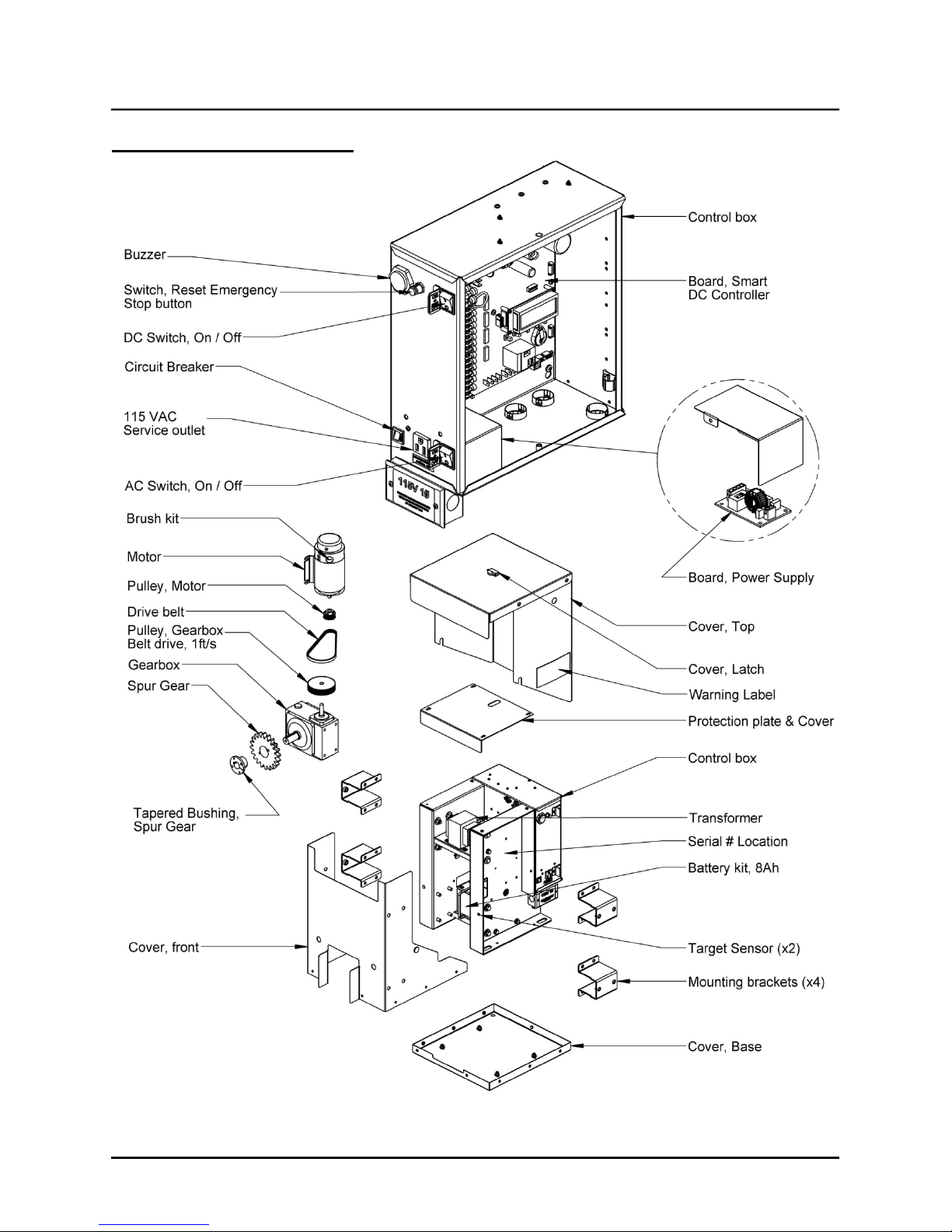
Kinetic Components
Kinetic Components
Note: Refer to Parts & Limited Warranty for Kinetic parts list.
Rev: A Intro-1

Intelligent Features: Smart DC Controller™
Introducing Kinetic DC
Thank you for purchasing our premium Kinetic DC™ slide gate operator. At Wallace International, we pride
ourselves on quality. Our new line electromechanical gate operators include a number of unparalleled user
benefits:
Robust
Power
Finesse
UPS backup and Solar ready
- The components on the Smart DC Controller™ are protected by opto-isolators which shield them
from power surges and lightning strikes.
- The Smart DC Controller provides variable speed control to a powerful, continuous duty 24V DC
motor which drives the gearbox. The electronics, motor and gear box are rated to operate in
temperatures that range from -13°F to 158°F (-25°C to 70°C).
Kinetic DC 15W is rated for gates up to 40 feet long and 1,500 pounds (12m and 682kg). Kinetic
DC 10FW is rate for gates up to 40ft and 1,000lbs. (12m and 454kg).
Solar options are available for both models.
- A variable rate of gate acceleration and deceleration, dependent upon gate weight and length,
assures very smooth handling.
– Two 12V, 8 amp hour (Ah) batteries will provide a fully functional gate
operator (up to 4000ft/1219m of gate travel) when AC power is unavailable. Four user-selectable
UPS modes are available.
12VDC and 24VDC are available to power accessory controls. An optional base extension is
required to provide space for the optional 50Ah batteries which support solar applications or usage
during extended power outages.
Intelligent Features: Smart DC Controller
Menus and User relays
gate function and two user relays, which can be configured for 22 different functions.
Independent adjustment for open and close gate speeds
Controller allows the installer to vary the open and close speed settings.
Intelligent Inherent Entrapment Sensor (IES)
stopping gate movement per UL 325 Safety Standards. The intelligent system monitors gate power
then adapts the IES to trip at an adjustable threshold above normal power.
Improved Liquid Crystal Display (LCD)
programming and troubleshooting.
USB communications port
upload system configurations using the Smart Touch Analyze and Retrieve Tool (S.T.A.R.T.)
software.
START software and diagnostics
latest software upgrade and have an invaluable troubleshooting tool for Wallace International
operators. To download this free software, visit the Hysecurity website at www.hysecurity.com
– The Smart DC Controller has 46 menu items to allow installer configuration of
– An easy-to-use menu on the Smart DC
– Any impediment to gate travel is sensed by the system,
– A 32-character LCD provides increased readability for
– A direct connect provides accessibility to download system diagnostics and
- With S.T.A.R.T. software loaded on a laptop computer, you can get the
™
.
Intro-2 Rev: A

Technical Support
For technical support, call your installer or authorized Wallace International distributor. Obtain the serial
number of your operator before calling. Refer to Kinetic Components on the front page. For the name of a
distributor near you, call Wallace International at 866-300-1110.
For information about Wallace International training for installers, maintenance personnel and end users,
refer to the company website at www.wallaceintl.com or call 866-300-1110.
Rev: A Intro-3

Installer’s Check List
Installer’s Check List
The following list provides a high level overview of the tasks involved in installing the Kinetic DC gate
operator. Take a moment to review the list and check off the items as you complete the install.
Make sure gate installation complies with ASTM F2200 Standard Specification for Automated Vehicular
Gate Construction. And, install the supplied WARNING sign on both sides of the gate.
Check for compliance with local codes, site conditions, and NEC standards.
Install tooth rack.
Install operator - (on gate post using 10x1.5 x 140mm hex bolts, lock washers, clamps and spacers.)
Connect red wire to DC Power Switch.
Turn DC Power ON.
Complete Initial Setup Menu programming.
Install the target magnet and make sure it is in line with and passes by the target sensor so it can be
recognized by the software programming.
Connect AC Power.
Connect all accessory devices.
Set the Close Timer (through the User Menu).
Set gate speed, if applicable (through Installer Menu). Refer to START (Smart Touch Analyze and Retrieve
Tool) in the Reference section.
Set IES sensitivity, if needed (through Installer Menu).
Check the Smart DC Controller software version. If needed, upload the latest version from
www.hysecurity.com
Program changes through the Installer Menu depending on the accessory devices that you have installed.
Give a copy of the operator instructions to the end user. Show the end user how to:
• Remove the operator cover. Turn the power o_ and on to demonstrate learn limits after DC/AC cycles.
. See Smart Touch Analyze and Retrieve Tool.
• Turn the DC power switch off, which disengages the motor, and manually push the gate.
• Test the red Emergency Stop Button located on the side of the control box. It can be accessed through a
hole in the cover. See illustration on page S-8.
Take photographs of the completed installation site and save it in your business files.
Intro-4 Rev: A
 Loading...