

WALKY WL1024, WL1024C Instructions And Warnings For Installation And Use
EN - Instructions and warnings for installation and use
IT - Istruzioni ed avvertenze per linstallazione e luso
FR - Instructions et avertissements pour linstallation et lutilisation
ES - Instrucciones y advertencias para la instalación y el uso
DE - Installierungs-und Gebrauchsanleitungen und Hinweise
PL - Instrukcje i ostrzeżenia do instalacji i użytkowania
NL - Aanwijzingen en aanbevelingen voor installatie en gebruik
WALKY
WL1024
WL1024C
Swing gate opener


EN
English – 1
ENGLISH
Contents
1 - WARNINGS AND GENERAL PRECAUTIONS . . . . . . . . . . . . . . . . . . . . 1
1.1 - Safety warnings . . . . . . . . . . . . . . . . . . . . . . . . . . . . . . . . . . . . . . . . . . 1
1.2 - Warnings for installation . . . . . . . . . . . . . . . . . . . . . . . . . . . . . . . . . . . . 1
1.3 - Warnings for use . . . . . . . . . . . . . . . . . . . . . . . . . . . . . . . . . . . . . . . . . . 1
2 - PRODUCT DESCRIPTION AND INTENDED USE . . . . . . . . . . . . . . . . . 1
3 - INSTALLATION . . . . . . . . . . . . . . . . . . . . . . . . . . . . . . . . . . . . . . . . . . . . 2
3.1 - Pre-installation checks . . . . . . . . . . . . . . . . . . . . . . . . . . . . . . . . . . . . . 2
3.2 - Usage limitation . . . . . . . . . . . . . . . . . . . . . . . . . . . . . . . . . . . . . . . . . . 2
3.3 - Preparatory work prior to installation . . . . . . . . . . . . . . . . . . . . . . . . . . . 3
3.4 - Installation of the gearmotor mod. WL1024C - WL1024 . . . . . . . . . . . . 3
3.4.1 - Establishing the length of the gearmotor arm . . . . . . . . . . . . . . 3
3.4.2 - Installation of a gearmotor with a STANDARD LENGTH ARM . . 3
3.4.3 - Installation of a gearmotor with a SHORTENED ARM . . . . . . . . 4
3.5 - Installation of the multi-purpose lamp mod. WLT on the gearmotor
model WL1024C . . . . . . . . . . . . . . . . . . . . . . . . . . . . . . . . . . . . . . . . . . . . . . 5
3.6 - How to remove the control unit . . . . . . . . . . . . . . . . . . . . . . . . . . . . . . . 5
3.7 - Adjusting the alignment of the gate leaves when closed . . . . . . . . . . . . 5
3.8 - Securing and releasing the gearmotor manually . . . . . . . . . . . . . . . . . . 5
4 - ELECTRICAL CONNECTIONS . . . . . . . . . . . . . . . . . . . . . . . . . . . . . . . 5
4.1 - Description of the electrical connections . . . . . . . . . . . . . . . . . . . . . . . . 5
4.2 - Connecting the power cable . . . . . . . . . . . . . . . . . . . . . . . . . . . . . . . . . 6
4.3 - Connecting the gearmotor without a control unit mod. WL1024 . . . . . . 5
4.4 - Connecting other devices . . . . . . . . . . . . . . . . . . . . . . . . . . . . . . . . . . . 5
4.5 - Addressing the connected devices . . . . . . . . . . . . . . . . . . . . . . . . . . . . 6
4.6 - Initialisation and connection check . . . . . . . . . . . . . . . . . . . . . . . . . . . . 6
4.7 - Recognition of the connected devices . . . . . . . . . . . . . . . . . . . . . . . . . 6
4.8 - Recognition of the positions of the mechanical stops . . . . . . . . . . . . . . 6
4.9 - Gate leaves motion check . . . . . . . . . . . . . . . . . . . . . . . . . . . . . . . . . . 6
5 - TESTING AND COMMISSIONING . . . . . . . . . . . . . . . . . . . . . . . . . . . . . 6
5.1 - Testing . . . . . . . . . . . . . . . . . . . . . . . . . . . . . . . . . . . . . . . . . . . . . . . . . 7
5.2 - Commissioning . . . . . . . . . . . . . . . . . . . . . . . . . . . . . . . . . . . . . . . . . . . 7
6 - PROGRAMMING THE CONTROL UNIT . . . . . . . . . . . . . . . . . . . . . . . . 7
6.1 - Level one programming (ON-OFF) . . . . . . . . . . . . . . . . . . . . . . . . . . . . 7
6.2 - Level two programming (adjustable parameters) . . . . . . . . . . . . . . . . . . 8
6.3 - Memory deletion . . . . . . . . . . . . . . . . . . . . . . . . . . . . . . . . . . . . . . . . . . 8
6.4 - Special functions . . . . . . . . . . . . . . . . . . . . . . . . . . . . . . . . . . . . . . . . . 8
7 - WHAT TO DO IF... (troubleshooting guide) . . . . . . . . . . . . . . . . . . . . . . 9
8 - FURTHER INFORMATION . . . . . . . . . . . . . . . . . . . . . . . . . . . . . . . . . . 10
8.1 - Connection of the OXI radio receiver . . . . . . . . . . . . . . . . . . . . . . . . . . 10
8.2 - Connection and installation of the back-up battery mod. PS424 . . . . . 10
8.3 - Connection of the Oview programmer . . . . . . . . . . . . . . . . . . . . . . . . 10
8.4 - Connection of the Solemyo solar power system . . . . . . . . . . . . . . . . . 10
9 - PRODUCT MAINTENANCE . . . . . . . . . . . . . . . . . . . . . . . . . . . . . . . . . 10
DISPOSING OF THE PRODUCT . . . . . . . . . . . . . . . . . . . . . . . . . . . . . . . . 11
PRODUCT TECHNICAL SPECIFICATIONS . . . . . . . . . . . . . . . . . . . . . . . 11
Product life span . . . . . . . . . . . . . . . . . . . . . . . . . . . . . . . . . . . . . . . . . . . . 12
EC DECLARATION OF CONFORMITY . . . . . . . . . . . . . . . . . . . . . . . . . . . 12
APPENDIX . . . . . . . . . . . . . . . . . . . . . . . . . . . . . . . . . . . . . . . . . . . . . . . . . . I
Instructions and warnings for the user . . . . . . . . . . . . . . . . . . . . . . . . . . . . . III
Images . . . . . . . . . . . . . . . . . . . . . . . . . . . . . . . . . . . . . . . . . . . . . . . . . . . . . X
1.1 - Safety warnings
• IMPORTANT! – This manual contains important instructions and warn-
ings regarding safety. Incorrect installation may cause serious injury. Before
commencing work, all sections of the manual must be read carefully. If in any
doubt, suspend installation and call the Nice Support Service for clarification.
• IMPORTANT! – This manual contains important instructions. Keep it for
future maintenance work and disposal of the product.
• IMPORTANT! – Under the latest European legislation, automatic door
and gate installations must be compliant with the standards specified in
Directive 2006/42/EC (formerly 98/37/EC) (the Machinery Directive) and
the standards EN 12445, EN 12453, EN 12635 and EN 13241-1 in particular, which enable conformity of the automated functionality to be de clared. In the light of the above, all work involving installation, connection, testing and maintenance of the product must be carried out
exclusively by qualified and competent technicians!
1.2 - Warnings for installation
• Before commencing the installation, check if the product is suitable for the
desired type of use (see “Usage limitation” paragraph 3.2 and the "Product
technical specifications”). If it is not suitable, DO NOT continue with the installation.
• All installation and maintenance work must be carried out with the au -
tomation system disconnected from the electricity supply. If the power
disconnection device cannot be seen from where the automation system is
positioned, then before starting work a notice must be attached to the disconnection device bearing the words “CAUTION! MAINTENANCE IN PRO GRESS”.
• The Control unit must be connected to an electricity supply line equipped
with protective earthing.
• Handle the product with care during installation, taking care to avoid crushing, denting or dropping it, or contact with liquids of any kind. Keep the product away from sources of heat and naked flames. Failure to observe the
above can damage the product, and increase the risk of danger or malfunction. Should this occur, suspend installation work immediately and contact
the Nice Support Service.
• Do not modify any part of the product. Prohibited modifications can only lead
to malfunctions. The manufacturer declines all responsibility for damage re sulting from unauthorized changes made to the product.
• If the gate or door being automated has a pedestrian gate, then the system
must include a control device that will inhibit the operation of the motor when
the pedestrian gate is open.
• The products packaging material must be disposed of in full compliance with
local regulations.
1.3 - Warnings for use
• The product is not intended for use by persons, including children, with limited physical, sensory or mental capacities, or who lack experience or knowledge, unless supervised or trained in the use of the product by a person
responsible for their safety.
• Any children near the automation system must be kept under supervision to
ensure that they do not play with it.
• Do not allow children to play with the fixed control devices. Keep remote control devices out of the reach of children.
WARNINGS AND GENERAL PRECAUTIONS
1
The devices comprising this product are designed to automate a gate or door
with one or two leaves. IMPORTANT! – Any other use apart from that
described herein, including in different environmental conditions from
those described in this manual is to be considered improper use and is
not permitted!
The principal component of the automation system comprises one or two electric gearmotors (according to the number of leaves to be automated), each
equipped with a direct current motor and epicyclic reduction gear. One of the
gearmotors (mod. WL1024C) has a control unit that controls its operation. The
Control unit consists of a board with a radio receiver for receiving the commands sent by the transmitter.
The control unit is designed for connection to several devices belonging to the
Opera system, the Bluebus system and the Solemyo solar powered system.
If it is mains powered, it can house a back-up battery (mod. PS424, optional
accessory) which in the event of a power cut (electricity black-out) guarantees
that the automated device will perform certain manoeuvres in the hours that follow.
In the event of a power cut, the gate leaves can be moved by releasing the
gearmotor with the dedicated key; to perform the manoeuvre manually please
see chapter 3.8.
PRODUCT DESCRIPTION AND
INTENDED USE
2

EN
2 – English
3.1 - Pre-installation checks
Before going ahead with the installation, check the integrity of the product components, and ensure the model chosen is suitable for its intended use and for
the environment in which it is to be installed.
• Check that all the material to be used is in excellent condition and suitable for
its intended use.
• Check that the ground-mounted mechanical stops are present both when
opening and closing the automation system.
• Check that the mechanical structure of the gate is suitable for the installation
of automation and compliant with locally applicable regulations (if necessary,
refer to the label on the gate). This product cannot be used to automate a
gate which is not already in good, safe working order, neither can it fix faults
caused by incorrect installation or poor maintenance of the gate.
• Check that the operating conditions of the devices are compatible with the
usage limitation declared (see paragraph 3.2).
• Move the gate leaves manually in both directions and ensure that the resistance to movement is constant at all points of travel (there should not be any
points where more force or less is required).
• Bring the gate leaves manually into a position at random, then let go and
check that they remain stationary.
• Check that the gearmotor fixing zone is compatible with its overall dimensions (fig. 1).
• Check that the place where the gearmotor is to be installed allows enough
space for its arm to execute its full range of movement.
• Check that there is sufficient room around the gearmotor for it to be released
manually when required.
• Ensure that the surfaces on which the various devices are to be installed are
strong and capable of ensuring a firm hold.
• Ensure that each device is installed in a position which is protected and does
not expose it to accidental impacts.
• Ensure that all the electrical cables to be used are the type listed in Table 1.
3.2 - Usage limitation
Before installing the gearmotor, check that its data complies with the usage limitation specified below and falls within the limits stated in the chapter entitled
“Product technical specifications”:
With FULL LENGTH motor arm (as shipped from the factory)
:
- maximum width of leaf: 1.60 m (= maximum weight of leaf: 110 kg)
- maximum height of leaf: 2 m
With SHORTENED motor arm (cut by the installer)
:
- maximum width of leaf: 1.60 m (= maximum weight of leaf: 100 kg)
- maximum height of leaf: 2 m
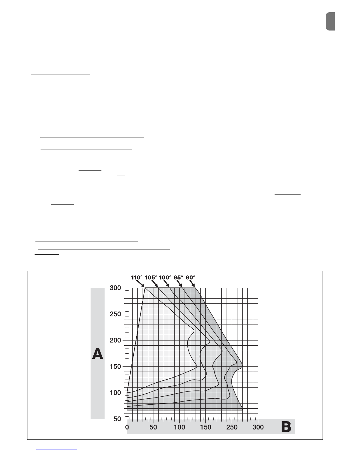
• Check to run: apply to Graph 1 the weight and width of the leaf; plot two lines
from these points and check that they intersect in one of the two grey areas
of
the graph. Important! - If the lines cross in the white area, this product cannot
be used to automate this particular gate.
• To enable the installation of the gearmotor, the minimum width
of the column
should be 80 mm.
• The gearmotor arm must be positioned in the upper part
of the gate leaf.
IMPORTANT! - The gearmotor must not be mounted upside down, i.e. with
the arm pointing downwards.
• The arms fastening bracket must be fitted at one of the strongest parts of the
leaf (e.g. the frame), in order to ensure a firm and safe hold;
• Check distance
“E” (fig. 7):
- If distance
“E” falls in the range 80 mm (minimum) to 299 mm (maximum),
the gearmotor arm will need to be shortened. In such conditions, the leaf will
be able to open by up to 90°.
- If distance “E” is 300 mm or more, there is no need to shorten the gear-
motor arm. In such conditions, the leaf will be able to open by up to 110°.
3.3 - Preparatory work prior to installation
Fig. 2 illustrates an example of an automated system, achieved using Nice
components:
a - Gearmotor with control unit mod. WL1024C
b - Gearmotor without control unit mod. WL1024
c - Multi-purpose lamp mod. WLT (to be installed on the gearmotor with con-
trol unit mod. WL1024C); see chapter 3.5 and the lamps own instruction
manual
d - Pair of photocells mod. MOFB
e - Digital keyboard (mod. MOTB) - Transponder reader (mod. MOMB) - Key
selector (mod. MOSE)
f - Pair of photocell posts
g - Opening and Closing mechanical stops
h - Electrical lock
These components are positioned according to a typical standard layout.
Referring to fig. 2, establish the approximate position in which to install each
component required for the system. Important – Before commencing installa-
tion, prepare the electrical cables necessary for your system, referring to fig. 2a
and to “Table 1 - Technical characteristics of the electrical cables”.
Important – While laying the tubes for the electrical cables, consider that due
to the possible build-up of water in the aqueducts, the connection tubes could
cause condensation to form inside the control unit and damage the electronic
circuits.
INSTALLATION
3
Connection Type of cable Maximum permitted length
A: POWER cable One 3 x 1.5 mm2cable 30 m (note 1)
B: ELECTRICAL LOCK cable One 2 x 1 mm2cable 6 m
C: BLUEBUS DEVICES cable One 2 x 0.5 mm2cable 20 m (note 2)
D: KEY SELECTOR cable Two 2 x 0.5 mm2 cable (note 3) 50 m
E: GEARMOTOR POWER cable One 3 x 1.5 mm2cable 6 m
EXTERNAL AERIAL cable (optional) One type RG58 screened cable 20 m (recommended less than 5 m)
Note 1 – If the power cable is more than 30 m long, you will need to use a cable with a wider cross-section (3 x 2.5 mm
2
) and you will have to install protective earthing near the automation system.
Note 2 – If the Bluebus cable is more than 20 m long, and up to a maximum of 40 m long, you will need to use a cable with a wider cross-section (2 x 1 mm
2
).
Note 3 – These 2 cables can be replaced with 1 single 4 x 0.5 mm
2
cable.
IMPORTANT! – The cables used must be suitable for the type of environment where they are installed.
TABLE 1 - Technical characteristics of the electrical cables
GRAPH 1
For full length
arm
For shortened
arm
WIDTH (m.)
WEIGHT (kg.)
Other available accessories include the receivers designed with “SM” connectors (SMXI, OXI, etc.).
The gearmotor with control unit (mod. WL1024C) is designed to accommodate
the installation of the multi-purpose lamp mod. WLT (see chapter 3.5), which
can operate as a flashing emergency light or courtesy light, depending on the
control unit programming. In addition, it can be used as a twilight by activating
a built-in light sensor; please refer to the relevant instruction manual for specifications.
EN
English – 3
3.4 - Installation of the gearmotor mod. WL1024C - WL1024
WARNINGS
• Failure to install correctly can cause serious injury to the person carrying out the work and those using the system.
• Before starting to assemble the automation system, carry out the preliminary checks described in paragraphs 3.1 and 3.2.
• The gearmotor arm can be shortened from the standard length provided. It needs to be reduced in length if there is a fixed obstacle close to
the gearmotor (such as a wall or post) impeding the full range of movement of the arm. In order to establish whether the arm needs to be
shortened,it is therefore necessary to follow the procedure in 3.4.1
before starting the installation
.
Assemble the component parts of the motor arm, referring to fig. 3. Do not
insert the Benzing retaining ring at this stage (fig. 4). N.B.! - The curved arm
must be positioned with the curved part towards the gate leaf, as shown
in fig. 5.
3.4.1 - Establishing the length of the gearmotor arm
01. Determine the VERTICAL position of the gearmotor: draw a horizontal
line on the column at the same height at which the fastening bracket for
the arm will be located on the leaf once the installation is complete.
02. Determine the HORIZONTAL position of the gearmotor:
a) Determine the maximum opening position of the leaf
: determine the
maximum opening angle (maximum 110°).
b) Measure distance B and determine distance A
:
1 - Measure distance B
on the column (fig. 5). This is the distance
between the fulcrum of rotation of the gate leaf and the surface of the column where the rear bracket of the gearmotor will be fixed.
2 - On Graph 2A, mark distance B
, as just measured, and trace a vertical
line from this point until it intersects with the area
which includes the angle
value measured in point a.
3 - At the points where the vertical line intersects with the area
, trace horizontal lines across column “A”, to determine the values which can be used
for distance A
. Then choose a value for A from this range, one of the
smaller values if possible.
4 - Mark distance A
on the column and trace a vertical line corresponding
to it (fig. 6).
5 - If there is a wall or other immovable obstacle near the vertical line,
measure the distance between this line and the obstacle (fig. 7): this is
distance E
.
IMPORTANT!
• If
distance E falls in the range 80 mm (minimum) to 299 mm (maxi-
mum), continue the installation with procedure 3.4.3
.
• If
distance E is 300 mm or more, continue the installation with pro-
cedure 3.4.2
.
5 - Release the gearmotor with the dedicated key (see chapter 3.8).
3.4.2 - Installation of a gearmotor with a STANDARD LENGTH ARM
Important! - This part of the installation can only be carried out after 3.4.1
has been completed.
01. Affix the gearmotor to the column (fig. 9)
:
a) Hold the gearmotor against the column(*) so that its vertical centre line
corresponds with the vertical line traced earlier (distance A), and its arm
corresponds with the horizontal line traced during procedure 3.4.1. Now
ensure that the gearmotor is completely levelled: if off-axis, it can cause the
automation to malfunction.
(*) Note - If the column surface is between 80 and 135 mm wide, then
before continuing with the installation, the gearmotors rear fastening bracket will need to be rotated by 90°. To rotate the bracket, refer to fig. 8.
b) Mark the fastening points, drill the required holes in the surface of the
column and insert the plugs; now fix the gearmotor in place using suitable
screws and washers.
02. Affix the gearmotor arm to the gate leaf (fig. 9)
:
a) Bring the gate leaf into the fully Closed position;
b) Open out the gearmotor arm to its maximum extension
;
c) Bring the arm up to the gate leaf and hold the fastening bracket against
the leaf.
d) Ensure that the gearmotor arm is levelled properly, and use a pencil to
mark the centre
of the slot profile on the bracket, to enable fine adjustments to be made to the closure alignment of the leaf in future (see paragraph 3.7).
e) Holding the bracket against the gate leaf with one hand, attempt to open
and close the gate completely, up to the respective mechanical stops.
Important! - If the movement of the arm is hampered during the test
by a wall or other fixed object, stop working on this procedure and go
to procedure 3.4.3.
f) Drill holes in the gate leaf at the points marked and remove the bracket
from the arm and affix it to the gate leaf with suitable screws.
g) Attach the arm to the bracket, inserting the pin and the Benzing retaining
ring. Important - Check that the bracket and the arm are completely level.
Loosen the screws of the bracket and adjust as required to ensure level.
h) Fix the end stops to the ground permanently, in the position
determined
at the start of the procedure. Important! - Check that the gate leaf closes
completely against the end stop. To make fine adjustments to the closure
alignment, refer to paragraph 3.7.
i) Finally, bring the leaf manually to around its midpoint of travel and secure
the gearmotor using the dedicated key (see chapter 3.8). Then manually
open the leaf by a few more centimetres.
03. If the gate being automated has two leaves, then to install the other gearmotor repeat all the actions described here in chapter 3.4.
GRAPH 2A
EN
4 – English
3.4.3 - Installation of a gearmotor with a SHORTENED ARM
Important! - This part of the installation can only be carried out after 3.4.1
has been completed.
01. Determine a new maximum opening angle for the gate leaf (max 90°)
:
ignoring the maximum opening position established for the leaf during procedure 3.4.1, bring the leaf to a new maximum opening position, ensuring
that the angle does not exceed 90°. Then hold the gate leaf provisionally in
this position using a ground-mounted stop.
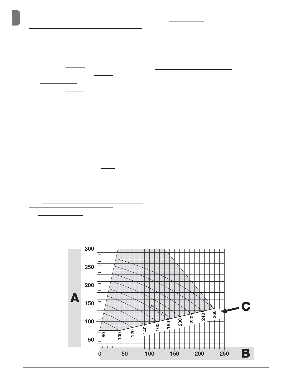
02. Determine distances A - B - C
:
a) Measure distance B
(fig. 10) on the column. This is the distance
between the fulcrum of rotation of the gate leaf and the surface of the column where the rear bracket of the gearmotor will be fixed.
b) On Graph 2B, mark distance B
as measured, and trace a vertical line
from this point.
c) On the column, determine the value for distance A
, at which to mount
the rear bracket of the gearmotor (refer to fig. 11). N.B.! - Choose a value
for A, the smaller the better
, in order to keep the motor free of the
obstacle.
d) On Graph 2B, mark distance A
as just measured and plot a horizontal
line from this point until it intersects with the vertical line traced earlier. The
meeting point of these lines defines distance C
, i.e. the distance required
between the two pins on the slotted arm (fig. 12). Example from graph 2B:
if the value of B is 105 mm and A is 143 mm, then point C is 182.
03. Affix the gearmotor to the column (fig. 13)
:
a) Hold the gearmotor against the column (*) so that its vertical centre line
corresponds with the vertical line traced earlier (distance A), and its arm
corresponds with the horizontal line traced during procedure 3.4.1. Now
ensure that the gearmotor is completely levelled: if off-axis, it can cause the
automation to malfunction.
(*) Note - If the column surface is between 80 and 135 mm wide, then
before continuing with the installation, the gearmotors rear fastening bracket will need to be rotated by 90°. To rotate the bracket, refer to fig. 8.
b) Mark the fastening points, drill the required holes in the surface of the
column and insert the plugs; now fix the gearmotor in place using suitable
screws and washers.
04. Shorten the slotted arm (fig. 14)
:
a) To reduce the length of the slotted arm to value C
(as established in
point 02-d), unscrew the nut, remove the stop, adjust the two pins so that
the distance between them is equal to value C, then fasten the nut in position provisionally.
05. Checking the length C of the slotted arm in this context (fig. 15 - 16)
:
a) Bring the gate leaf into the fully Closed position;
b) Fully open the gearmotor arm to its maximum extent (see 15, phase 1);
c) Bring the arm up to the gate leaf and hold the fastening bracket against
the leaf: Important!
- push the curved arm against the leaf, until it is
secured (maximum opening - see fig. 15, phase 1a).
d) Ensure that the gearmotor arm is levelled properly, and use a pencil to
mark the centre
of the slot profile on the bracket, to enable fine adjustments to be made to the closure alignment of the leaf in future (see paragraph 3.7).
e) Provisionally attach the bracket to the gate leaf and bring the leaf into its
maximum opening position against the ground-mounted stop.
f) With the leaf in this position, perform the checks shown in fig. 16 (run a
wire over the two pins of the slotted arm, as far as the leaf hinge). Impor-
tant! - If, in relation to the hinge,
the wire appears in position “BB” as in fig.
16, it will be necessary to extend distance C by a few millimetres. This
must be repeated until the wire reaches position “AA” as in fig. 16 and the
arm is no longer obstructed by the wall or other fixed obstacles.
06. Cutting the slotted arm (fig. 17)
:
After checking that the articulation is operating correctly, cut the slotted
arm in the following manner.
a) Trace a line on the slotted arm in the position exactly as indicated in fig.
23, phase 1. Then remove the arm from the bracket and cut the part of the
arm which is not required.
b) Re-assemble the components of the arm (fig. 3).
07. Affix the gearmotor arm tot he gate leaf (fig. 18
):
a) Drill holes in the gate leaf at the points marked.
b) Remove the bracket from the arm and affix it to the gate leaf with suit-
able screws.
c) Attach the arm to the bracket, inserting the pin and the Benzing retaining
ring. Important - Check that the bracket and the arm are completely level.
Loosen the screws of the bracket and adjust as required to ensure level.
d) Fix the end stops to the ground permanently, in the position
determined
at the start of the procedure.
Important! - Check that the gate leaf closes completely against the end
stop. To make fine adjustments to the closure alignment, refer to paragraph
3.7.
e) Finally, bring the leaf manually to around its midpoint of travel and secure
the gearmotor using the dedicated key (see chapter 3.8) Then manually
open the leaf by a few more centimetres.
08. If the gate being automated has two leaves, then to install the other gearmotor repeat all the actions described here in chapter 3.4.
GRAPH 2B

EN
English – 5
The electrical connection of the various devices (photocells, digital keyboards,
transponder card readers, etc.) of the automation system with a control unit is
carried out with the Nice “Bluebus” system. This system makes it possible to
carry out the electrical connections with the use of just 2 wires along which
both the electricity supply and the communication signals travel. The electrical
connection to be used is parallel and does not require any polarity to be
observed. During the recognition phase, every device connected to the control
unit will be recognised individually by the latter, thanks to a univocal code. Every
time a device is added or removed, you must carry out the control unit recognition phase (see paragraph 4.7).
ELECTRICAL CONNECTIONS
4
3.5 - Installation of the multi-purpose lamp mod. WLT on the
gearmotor model WL1024C
Warning – WLT can operate as a flashing emergency light or courtesy light,
depending on the control unit programming.
Follow the installation steps shown in fig. 21, making sure the right sequence is
followed and the following warnings are adhered to:
• for stage 4 – Rotate the power unit in the direction of the arrow, keeping a
careful eye on the cables underneath that connect it to the gearmotor.
• for stage 7 – Open out the cables fully and insert the connector into the
FLASH output as shown; secure the cables by inserting them in the cable
gland.
• for stage 11 – Position the electrical board on the pin of the base, depending
on the desired usage: A = diffuse light; B = directional light beam (in this case,
the light beam can be directed by blocking the board in one of the holes on the
base).
• for stage 12 – Open out the cable fully, cut the excess portion and position
the cables in such a way that they do not cast any shadows over the LEDs and
the light sensor fitted on the back of the electrical board.
• for stage 13 – The arrow on the cover and the one on the base should align.
Ensure the 4 cogs on the base fit into the grooves inside the cover.
3.6 - How to remove the control unit
01. Remove the gearmotors lower cover (fig. 19);
02. Undo the 4 screws of the cable sleeve support and remove it (fig. 24,
phase 1-2);
03. Pull the control unit about 4 centimetres in the direction of the arrow, and
detach the motor connector (fig. 24, phase 3-4);
04. Finally, remove the control unit completely;
Important! - When reconnecting the motor to the control unit, observe the
polarity of the connector (this can only be inserted one way around!).
3.7 - Adjusting the alignment of the gate leaves when closed
01. Remove the slotted arm from the fastening bracket on the gate leaf;
02. Loosen the screws on the bracket and move it by a few millimetres towards
the gearmotor;
03. Then replace the slotted arm in the bracket, close the leaf and check that it
is both aligned with the other leaf and in contact with the end stop. Impor-
tant! - If necessary, repeat point 02 until an optimum alignment is achieved;
04. Drill a hole in the leaf, to correspond to the hole in the centre of the fasten-
ing bracket, and insert a screw. Then fix the bracket permanently in place
by tightening the three screws;
05. Finally, attach the slotted arm to the bracket, inserting the pin and the Ben-
zing retaining ring.
3.8 - Securing and releasing the gearmotor manually
The gearmotor is equipped with a mechanical system which allows the gate to
be opened and closed manually.
These manual operations are required in the event of power cuts, operational
faults, or during installation.
Releasing (fig. 22-A):
01. Rotate the release disc clockwise by 90°;
02. Insert the key into the release pin;
03. Turn the key by almost a full turn clockwise.
04. Remove the key from the pin and rotate the release disc anticlockwise by
90° so that the hole is blocked.
05. The gate leaf can now be moved manually into the required position.
Securing (fig. 22-B):
01. Turn the key anticlockwise in the release pin and move the gate leaf manu-
ally until you can hear the leaf engage mechanically with the drive mechanism.
02. Remove the key from the pin and rotate the release disc anticlockwise by
90° so that the hole is blocked.
4.1 - Description of the electrical connections (fig. 23)
M1 gearmotor output 1
ELS output for 12 VAC electrical lock (max 15 VA). [*]
BLUEBUS input for compatible devices (MOFB, MOFOB, MOB and MOTB)
STOP input for devices which, when activated, cause the manoeuvre in
progress to halt immediately, followed by a brief inversion; possibility of connecting NO, NC contacts or devices with a 8.2 kΩ con-
stant resistance output (sensitive edges). Each device connected to
this input is recognised individually by the control unit during the
recognition phase (paragraph 4.7); after this phase, if the control
unit detects any variation with respect to the status recognised, it
causes a STOP. One or more devices - including different ones can be connected to this input:
– several NO devices can be connected in parallel, with no limits as
to quantity;
– several NC devices can be connected in parallel, with no limits as
to quantity;
– 2 devices with a 8.2 kΩ constant resistance output can be con-
nected in parallel. If there are more than 2 devices, they need to be
connected in a cascade configuration with a single termination
resistance of 8.2 kΩ;
– 2 NO and NC devices can be connected in parallel, connecting in
series with the NC contact a 8.2 kΩ resistance (this makes the
combination of 3 NO - NC and 8.2 kΩ devices possible)
P. P. input for control devices which, when activated, cause the Step-
step manoeuvre to take place; possibility of connecting NO contacts
AERIAL input for the aerial of a radio receiver
[*] The ELS output can be programmed with other functions using the Oview
programmer (see chapter 8.3).
4.2 - Connecting the power cable
WARNING: The electricity supply line must be equipped with a device which
ensures the complete disconnection of the automation system from the mains.
The disconnection devices contacts must have an opening distance which is
sufficient to achieve full disconnection in category III overload conditions, in
conformance with the rules of installation. When the need arises, this device
ensures that the power is disconnected quickly and safely; it must therefore be
positioned where it can be seen from the automation system. If, however, it is
not located in a visible position, it must be provided with a system to prevent
the power supply being reconnected accidentally or without authorisation, in
order to avoid any risk. The product is not supplied with a disconnection
device.
IMPORTANT!
– The connection must be carried out exclusively by qualified experts.
– All electrical connections must be carried out without any mains electri-
cal power supply and with the back-up battery disconnected - where
present in the automation system.
01. Access the power unit by undoing the 3 screws in the gearmotors upper
cover and slowly rotate the cover in the direction of the arrow (fig. 24),
keeping a careful eye on the cables underneath;
02. Connect the phase and neutral wires to the power unit terminal board,
observing the instructions on the label; close the earth cable grommet
using the screw (fig. 25): care required! -the terminal should be pointing
towards the opening from which the power cable emerges;
03. Then pull the power cable towards the control unit, so that it is just long
enough to allow the power unit to rotate and the cover to close;
04. Close the power unit cover; tighten the screws on the cable gland; insert
the control unit into its seat, and remount the cable sleeve support;
Important! - Fasten the cover of the power unit with all the screws
and ensure that the seal is well positioned in its seat. If the seal or one
of the screws is missing, this can compromise the electronics inside.
4.3 - Connecting the gearmotor without a control unit mod.
WL1024
01. Remove the lower cover of the gearmotor without control unit, as shown in
fig. 19;
02. Using a Phillips screwdriver, undo the 4 screws of the cable sleeve support
and remove it (important! - do not lose the 2 spacers).
03. Loosen the two screws on the cable gland and feed the connection cable
through; connect the 3 cables to the terminal board, observing the symbols as labelled; then tighten the screws of the cable gland.
04. Adjust the 2 feet inside the gearmotor with an Allen key, until they are fully
resting on the column (fig. 20, phase 5).
05. Insert the 6 rubber plugs (provided in the bag containing the small parts) in
the holes in the cable sleeve support; cut the edge of the cable sleeve support (fig. 20, phase 6); put the 2 spacers back into position; remount the
cable sleeve support and replace the gearmotors lower cover.
4.4 - Connecting other devices
If you need to power further devices in the system, such as a transponder card
reader or the light for the key selector, these devices can be connected to the
EN
6 – English
control unit on terminals “P.P. (positive)” and “STOP (negative)” (fig. 26). The
supply voltage varies from 18 to 31 VDC when mains or solemyo operated and
from 11 to approx. 14 VDC when operating on back-up battery PS424. The
maximum available current is 200 mA.
Note – The voltage available in terminals “P.P.” and “STOP” remains present
even when the “Stand By” function is activated on the board.
4.5 - Addressing the connected devices
To allow the control unit to recognise the devices connected to the Bluebus
system, these devices need to be addressed. This must be done by correctly
positioning the electric jumper of each device, referring to the respective
instruction manual of each individual device.
4.6 - Initialisation and connection check
Once you have powered the control unit, carry out the following checks:
• after a few seconds, check that the “Bluebus” LED (fig. 26) flashes regularly
at a frequency of 1 flash per second;
• check that the LEDs of the photocells, both TX and RX, emit flashes. The type
of flashing emitted, at this stage, is not significant;
• check that the WLT multi-purpose lamp is turned off (set on flashing function)
and connected to the FLASH output on the power supply.
If this does not happen, cut off the electricity supply to the control unit and
check the various electrical connections previously carried out.
4.7 - Recognition of the connected devices
Once initialisation is complete, the control unit must recognise the devices connected to the “Bluebus” and “Stop” inputs.
IMPORTANT! – The recognition phase must be carried out even if the
control unit is not connected to any devices.
The control unit is designed to recognise individually the various devices connected to it thanks to the recognition procedure and it can also detect with a
very high degree of precision any possible problems. Consequently, the recognition of devices must be carried out each time a device is connected or
removed.
LEDs “L1” and “L2” on the control unit (fig. 26) emit slow flashes to indicate
that recognition needs to be carried out:
01. Press and keep pressed keys “” and “Set” (fig. 26) simultaneously.
02. Release the keys when LEDs “L1” and “L2” begin to flash quickly (after
approximately 3 seconds).
03. Wait a few seconds for the control unit to complete the device recognition
phase.
04. At the end of this phase, the “Stop” LED should be turned on and LEDs
“L1” and “L2” should turn off (LEDs “L3” and “L4” may start to flash).
4.8 - Recognition of the positions of the mechanical stops
After the recognition of devices (paragraph 4.7), the control unit must recognise
the positions of the mechanical stops (maximum Opening and maximum Closure);
During this phase, the angle of aperture of the leaf is detected from the closing
mechanical stop to the opening mechanical stop. It is vital that the mechanical
stops are fixed and sufficiently sturdy.
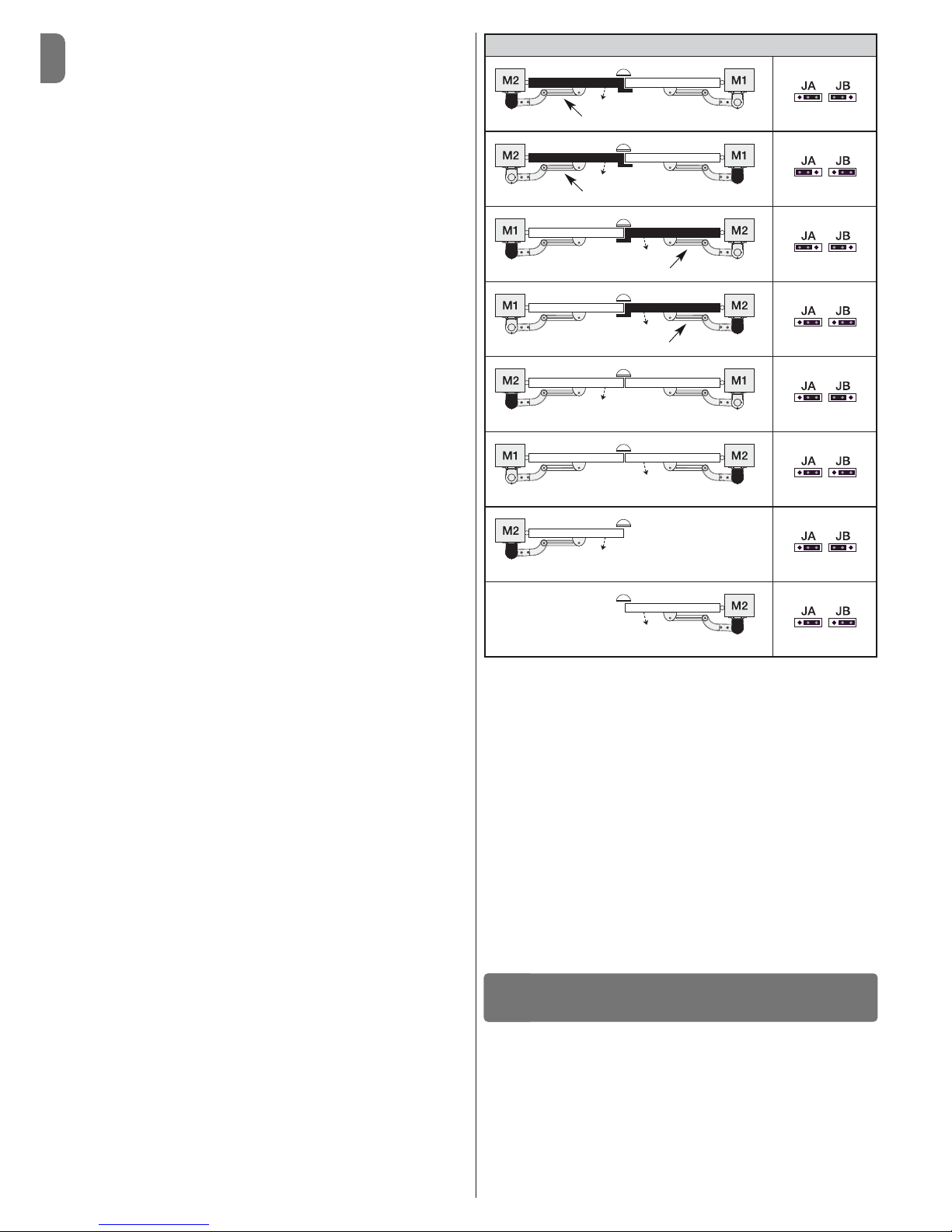
01. Identify the figure corresponding to your system in Table 2, fix the electric
jumpers JA and JB in place on the control unit, in the position as indicated
in this figure.
02. Release the gearmotors with the dedicated keys (see chapter 3.8) and
bring the leaves to their midpoint of travel so that they are free to open and
close; then secure the gearmotors.
03. On the control unit, press and keep keys “Set” and “” pressed simulta-
neously;
04. When LEDs “L3” and “L4” begin to flash quickly, (after approximately 3
secs.) release the keys;
05. Check that the automated system performs the following sequences of
manoeuvres:
a - Slow closure of gearmotor M1 to the mechanical stop
b - Slow closure of gearmotor M2 to the mechanical stop
c - Slow opening of gearmotor M2 and gearmotor M1 to the mechanical
stop
d - Complete quick closure of gearmotors M1 and M2
• If the first manoeuvre of one or both leaves is not a closing movement,
press any key to halt the recognition phase and check the positioning of
electric jumpers JA and JB referring to Table 2; otherwise, check the polarity of the motor without control unit (mod. WL1024).
• If the first motor to start the closing movement is not M1, press any key
to halt the recognition phase and check the positioning of electric jumpers
JA and JB, referring to Table 2.
• If a device is activated during the recognition phase (photocells, key
selector, pressing of a key, etc.), the recognition phase is immediately halted. It must be repeated in full.
06. At the end of the closing manoeuvre of both motors (d), LEDs “L3” and
“L4” switch off to indicate that the procedure was completed successfully.
4.9 - Gate leaves motion check
At the end of the recognition of the positioning of the mechanical stops, we recommend you make the control unit perform a few opening and closing
manoeuvres, in order to ensure the gate moves correctly, to check for any
assembly and adjustment defects or other problems:
01. Press the Open key (fig. 26) and check that the Opening manoeuvre
includes an acceleration phase, a phase at constant velocity, a deceleration phase and that the leaves stop against the opening mechanical end
stop.
02. Press the Close key (fig. 26) and check that the closing manoeuvre
includes an acceleration phase, a phase at constant velocity, a deceleration phase and that the leaves stop against the closing mechanical end
stop.
03. Check, during manoeuvres, that the flashing performs certain flashes at 0.5
second intervals with the flashing on and 0.5 seconds with the flashing off.
These are the most important phases in the installation of the automation system, in order to guarantee maximum system safety. Testing can also be used to
check the devices in the automation system regularly. The automation system
testing and commissioning phases must be carried out by qualified experts
who must be responsible for determining the tests necessary to check the
solutions adopted vis-à-vis the risks involved, and to check the observance of
all legal and regulatory obligations: in particular all the requirements of the EN
12445 standard which sets forth the test methods for checking automated
gates.
Additional devices must undergo specific testing, both in terms of functionality
as well as their correct interaction with WALKY.; please refer to the relevant individual instruction manuals.
TESTING AND COMMISSIONING
5
Overlapping leaf
Overlapping leaf
Overlapping leaf
Overlapping leaf
Control unit
Control unit
Control unit
Control unit
Control unit
Control unit
Control unit
Control unit
TABLE 2
EN
English – 7
5.1 - Testing
The sequence of steps to take to carry out testing refers to a typical system (fig. 2):
1 Release the gearmotors manually and check that when you operate the
leaf, at the point designed especially for the manual manoeuvre, the leaves
can either be opened or closed with a force of less than 390 N.
2 Check that the leaf, when left in any position along its travel, does not
move.
3 Secure the gearmotors (see chapter 3.8).
4 Check that the screw connections are screwed in tightly.
5 Using the control devices (transmitter, command button, key selector, etc.),
perform some Gate Opening, Closing and Stop tests, making sure the
movement of the leaves corresponds with each test. It is a good idea to
carry out several tests in order to evaluate the movement of the leaves and
pinpoint any assembly or adjustment defects as well as to check for any
particular points of friction.
6 Check one by one that all the safety devices in the system work properly
(photocells, sensitive edges, etc.). When a device is activated, the “BLUEBUS” LED on the control unit emits two quicker flashes to confirm that
recognition has taken place.
7 If the hazardous situations caused by the movement of the leaves have
been safeguarded by limiting the force of impact, the force must be measured in accordance with the EN 12445 standard and, if necessary, if the
control of the “gearmotor force” is used as an aid to the system to reduce
the force of impact, try and then find the adjustment that achieves the best
results.
8 Affix permanently a label describing how to release the gearmotor manual-
ly in an area adjacent to the automation system.
5.2 - Commissioning
Commissioning can only take place once all the testing phases have been
carried out successfully.
1 Put together the automation systems technical file, which should include
the following documents: an overall diagram of the automation system, the
diagram of the electrical connections made, the current risk analysis and
the related solutions adopted, the manufacturers declaration of conformity
for all the devices used and the declaration of conformity filled in by the
installer.
2 Affix a data plate onto the gate which specifies the following information, at
least: the type of automation system, the name and address of the manufacturer (responsible for the commissioning), the serial number, the year of
manufacture and the EC mark.
3 Fill in the declaration of conformity of the automation system and hand it
over to its owner.
4 Fill in and hand over to the owner of the automation system the “Users
guide” of the automation system.
5 Fill in and hand over to the owner of the automation system the “Mainte-
nance schedule” which contains instructions on the maintenance of all the
devices in the automation system.
6 Before commissioning the automation system, inform the owner of all the
hazards and residual risks entailed.
For all the documentation mentioned, the Nice technical support service
provides the following: instruction manuals, guides and precompiled forms.
Also visit: www.nice-service.com
TABLE 5 - Level one functions
LED Function Description
L1 Automatic close
L2 Close after photo
L3 Always close
L4 Stand by (Bluebus)
Function ACTIVATED: after an opening manoeuvre, there is a pause (equal to the programmed pause Time) after which the control unit auto-
matically performs a closing manoeuvre. The factory set pause time is 30 sec.
Function
DEACTIVATED: operation is “semi-automatic”.
Function
ACTIVATED: if the photocells are activated during an opening or closing manoeuvre, the pause time is reduced to 5 sec. irrespective of
the programmed “pause time”.
With the “automatic close” function deactivated, if the photocells are activated during the closing manoeuvre, the “automatic close” is activated
with the programmed “pause time”.
Function
ACTIVATED: in the event of a power cut, albeit brief, when the electricity supply returns the control unit detects the open gate and auto-
matically starts a closing manoeuvre, after 5 sec. of pre-flashing.
Function
DEACTIVATED: when the electricity supply returns, the gate will remain as is.
Function
ACTIVATED: 1 minute after the manoeuvre is finished, the control unit turns off the “Bluebus” output (connected devices) and all LEDs
except for the Bluebus LED which will flash more slowly. When the control unit receives a command, it restores normal operation (with a short
delay). This function is designed to reduce consumption levels, which is a key feature when battery or photovoltaic panel powered.
There are three keys on the control unit. These are OPEN (), STOP (SET) and
CLOSE () and they can be used to operate the control unit during the testing
phases as well as for programming the functions available.
The programmable functions available are arranged on 2 levels and their operating status is indicated by the 4 LEDs (L1 ... L4) on the control unit (LED on =
function activated; LED off = function deactivated).
Use the programming keys (fig. 26):
OPEN (): – key to control the gate opening; – selection key during the pro-
gramming phase.
STOP/SET: key to stop a manoeuvre; when pressed for more than 5 seconds,
it allows you to enter the programming phase.
CLOSE (): – key to control the gate closing; – selection key during the pro-
gramming phase.
6.1 - Level one programming (ON-OFF)
All level one functions are programmed at the factory to “OFF” and can be
changed at any time. To check the various functions please see Table 5. For
the programming procedure, please see Table 6.
Note – These procedures can be performed again at any time, even after a new
device has been connected to the control unit.
IMPORTANT – The programming procedure has a maximum time of 10 seconds between one key and another being pressed. After this time, the procedure ends automatically, storing the changes made up until that moment.
PROGRAMMING THE CONTROL UNIT
6
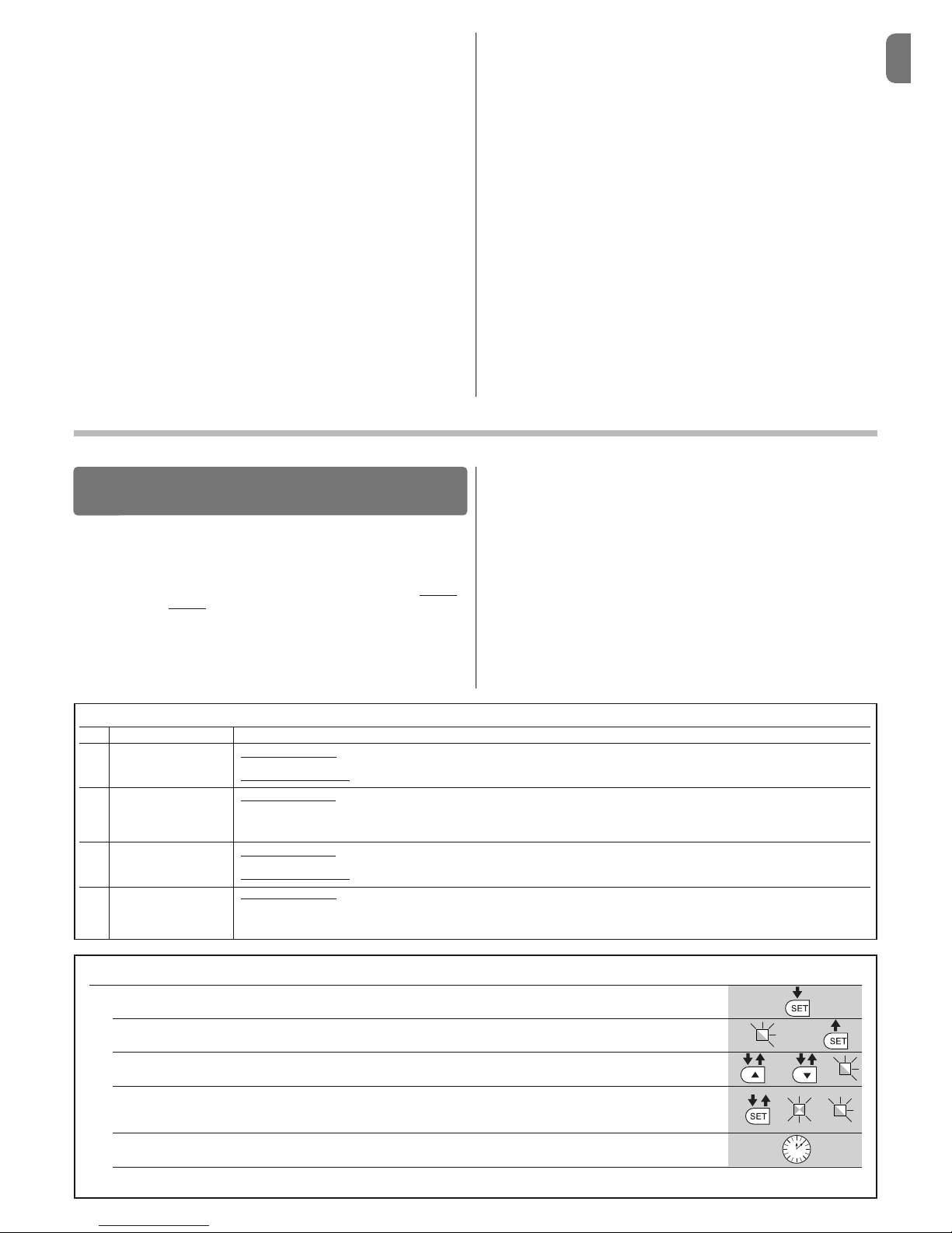
TABLE 6 - Level one programming procedure
01. Press and keep key “Set” pressed for approximately 3 seconds;
02. Release the key when LED “L1” begins to flash;
03. Press key “” or “” to move the flashing LED to the LED representing the function you wish to change;
04. Press the “Set” key to change the status of that function:
(brief flashing = OFF - long flashing = ON);
05. Wait 10 seconds (maximum) to exit programming mode.
Note – To program other functions to “ON” or “OFF” when the procedure is in progress, repeat steps 03 and 04 during the phase itself.
L1
or
3 s
10 s
 Loading...