


Rambler Sprayer
Handbook
Operating Instructions
& Parts List
www.walkoversprayers.com
sales@walkoversprayers.com
Tel: 0845 521 1209 Fax: 01269 844636

CONTENTS OF THE PACKING CASE
1 x Machine body complete
2 x Handle bars
1 x Spray Boom assembly
1 x Plastic bag containing:
4 x Handle bolts, wingnuts and washers
2 x Cable Clamps
1 x Instruction manual and Warranty
ASSEMBLY INSTRUCTIONS
The RAMBLER sprayer has been factory
tested prior to packing and only requires
the handles and the spray boom assembly
to be fitted.
Fit the handlebars into position using the
nuts, bolts and washers from the fixing bag.
The boom assembly can be fitted to the
main frame in two positions. The upper
position should be suitable for most
purposes. Take the boom assembly and
attach it to the main frame by using the
clamps. The boom is marked showing its
centre position, and this should be carefully
aligned into the centre of the fixing clamp.
BEFORE tightening the clamp the machine
should be lifted into its normal working
position and the boom nozzles checked to
ensure they are parallel to the ground.
Adjust the boom position and rotation as
necessary, re-check, then tighten the clamp
fixings. Attach the inlet wing nut to the
boom inlet housing. The machine is now
ready for testing.
TESTING
A trial run should be carried out on a dry
concrete surface to check that the nozzles
are in alignment. This should be carried out
using clean water to ensure everything is in
working order.
Half fill the container with cold water,
replace the filler cap & filter and move off at
a steady working place similar to the speed
of mowing.
This will prime the pump mechanism and
water will spray from the nozzles, showing
that all air has been bled from the system.
If an airlock remains in the system, unscrew
the two diaphragm check valve caps and
push the machine until water flows through
the system. Tighten the two caps and then
push. The machine will then start to spray.
DO NOT over tighten the diaphragm caps.
They are fitted in order to clear the spray
system of air & other small blockages.
OPERATING INSTRUCTIONS
When filling the machine, add sufficient
liquid treatment to cover the area needing
treatment or a pro-rata amount if only part
filling. Pay careful attention to which colour
nozzle is fitted at the time of spraying to
avoid any over or under application of
chemical. Always follow the chemical
manufacturers instructions relating to the
specific area. In many instances dilution
rates of chemicals are not critical, but in
some cases where a greater volume of
water is needed, then two x half strength
applications are recommended, spraying
where possible in a chequer board fashion
in North to South and East to West
directions.
SPRAY WIDTH
The RAMBLER has a spray width of 40
inches (1016mm). In common with all
Walkover sprayers, the spray pattern tails
off on the extreme edge of the treated
swath which is compensated for when
treating the return track. You must therefore
always ensure your return track is 40”
(1016mm) from the datum point of your
previous pass to achieve correct coverage.
A set of red nozzles are provided with the
machine. Nozzles giving alternative
coverage areas for the 25 litre (5.5 gallons)
loading as follows:
(a) With standard nozzle fitted, Red
ANDT 2.0, one full tank covers 825
sq. metres (1000 sq. yards)
equivalent to 298.6 litres/hectare
(26.6 gallons/acre)
(b) Alternative nozzle, Grey TF VP 3
delivers to one full tank 500 sq.
metres (670 sq. yards) equivalent
to 449 litres/ hectare (40
gallons/acre)
N.B The coverage areas for each nozzle
may vary plus or minus 5% depending on
the speed of operation and variations of the
terrain.

NOZZLE ASSEMBLY
The diaphragm control valve assembly is
fitted with a quick fit self- aligning cap.
When fitting the cap and nozzle, the selfaligning cap will ensure that the nozzle
remains in alignment. If the nozzle drips or
the spray pattern is distorted, this may be
caused by a minute blockage in the
diaphragm valve or nozzle. To remove the
nozzle tip, rotate the cap a half turn
anticlockwise, when viewing from the front.
Always ensure the nozzle seal is in place
on reassembling.
Treat all components with care, as they are
precision made to give a long and accurate
working life.
PUMP AND WHEEL REMOVAL
Should the pump at any stage during the
machine’s working life cause trouble it can
easily be removed and returned to Aztec for
repair or replacement. Work on the inside
of the pump can only be carried out by the
manufacturer and NO attempt should be
made to dismantle this unit otherwise the
guarantee becomes invalid.
If the tyre in the machine is punctured, the
wheel and pump need to be removed as
follows:
Remove the stainless steel elbow retaining
the spring clip and then each of the pipe
elbows from the pump. These elbows are a
push fit and are detached by pulling at a
slight angle. Remove the spring dome nuts
from either side of the wheel. Pull the pump
and axle assembly away from the bearing
spacers, taking care to remember their
respective positions for re-assembly. To
reassemble the unit, reverse the foregoing
operation ensuring that the wheel valve is
mounted on the opposite side to the pump.
CLEANING AND STORAGE
Always thoroughly clean the sprayer
after use. Flush through the whole system
with clean water using a small amount of
mild household detergent when toxic
chemicals have been used. It is very
important not to allow chemicals to dry out
in the pump mechanism that could
granulate and score the interior surfaces.
This could impair the performance of your
machine.
Where temperatures below zero degrees
are likely to be experienced, ensure that all
liquid has been drained from the machine
by removing the hose from the pump. This
elbow is a snap fit and pulls out quite easily
at a slight angle. Rotate the drive wheel to
empty the pump and pipe work and
reconnect the pipe into the pump. A small
amount of car anti-freeze introduced into
the pipe and pump system will give
excellent protection.
DO NOT empty chemicals in areas where
contamination may occur.
FILTRATION
A basket filter is located under the filler cap
in the tank and should remain in position at
all times, except when removing for
cleaning. Clean as required.
TYRE PRESSURES
The tyre pressure should be maintained at
20 to 22 p.s.i. DO NOT inflate over 25 p.s.i.
NEVER
1. Add concentrated active
ingredients to an empty tank, this
will result in pure product entering
the delivery pump and pipe lines.
2. Leave the sprayer in winter storage
with liquid in the tank or pipe work.
Severe frost could distort the pump
and burst the pipes.
ALWAYS
Ensure the container is half full of clean
cold water at the outset of your spraying
operation and the pump primed before
adding concentrated chemical.
In the case of highly viscous concentrates
and soluble powders, pre-dilute the product
to be applied in a watering can or bucket
with sufficient water to ensure it is
completely dissolved.
Half fill the tank with clean cold water. Add
the required amount of product and top up
to the 20 litre (4.4 gallon) level with water
and replace the cap. Rock the unit
backwards and forwards a few times to
ensure satisfactory mixing and then
commence spraying, maintaining a steady
pace. If a smaller are is to be treated fill the
tank to the appropriate level.
The RAMBLER sprayer stops spraying
immediately it ceases to travel forward. To
move the sprayer in a full condition (from

one area to another) without spraying, pull
backwards, or switch the valve on the
handle to the off position.
PRECAUTIONS
The manufacturer sets the pump
mechanism. Any tampering with the pump
setting may change the performance of
your machine and will render your
guarantee void.
Some of the chemicals that can be applied
by this machine onto grass areas and
driveways require special precautions for
use. Protective clothing including boots,
gloves and masks may be necessary and
therefore individual manufacturer’s
recommendations for the particular
chemical must be closely adhered to.
WALKOVER Sprayers Ltd. disclaims any
responsibility for misuse of any proprietary
brand of chemical applied by a machine of
their manufacture. All reasonable care is
taken to ensure correct dosage application
of known chemical formulations but
Walkover do not guarantee either their
efficiency or accept any responsibility or
damage resulting from user’s mistakes in
assessing dilution rates.
Experience has shown that combined
mixes of chemicals, i.e. fungicides and
weed killers, can often interact, resulting in
the formation of gelatinous substance
which can crystallise if left in the machine
after use. This solidifies within the pump
and nozzles and can in extreme instances
completely destroy the pump mechanism.
Many propriety brands of garden and
horticultural chemical are sold in the form of
Soluble powder or Crystals.
The RAMBLER sprayer will satisfactorily
apply these chemicals always providing
that the crystals or powder are
pre-mixed
tank and assuming that the chemical in
question is entirely soluble.
NEVER leave a soluble powder or a crystal
solution, or even an organic product, to
stand in the machine for any period of time
as sediment may form in the system and
the concentration being applied may be too
strong and cause scorching. It may also
find it’s way into the pump mechanism
before adding to the sprayer
completely
causing damage to the seals or internal
components.
DO NOT mix proprietary brands of
chemicals or treatments unless assured
of their compatability.
Please Note. Powder or crystalline
substances which require diluting & mixing
( not liquid concentrates ) such as sulphate
of iron should be used with caution.
Treatments that have not been thoroughly
mixed or that have been allowed to settle in
the tank can damage your sprayer because
such materials are abrasive. Please
exercise care and flush your sprayer
thoroughly after use.
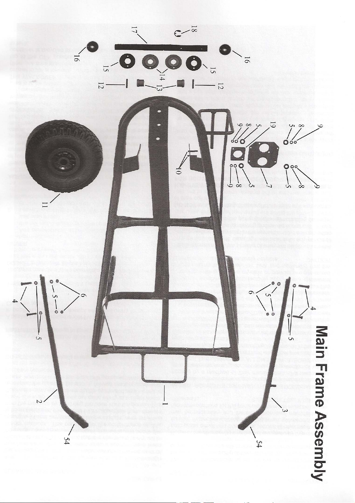


RAMBLER PARTS LIST:
Item Number Quantity Part Number Description
1 1 W1106 Main Frame
2 1 W1619 Handle L/H
3 1 W1633 Handle R/H
4 6 W1130 M6 x 35 Hex Head Set Screw
5 10 W1036 M6 Plain Washer
6 6 W1041 M6 Nut
7 1 W1108 Plate - Pump
8 4 W1068 M4 Spring Washer
9 4 W1043 M4 Nut
10 2 W1113 Dowel Pin
11 1 W1345 12” Pneumatic Wheel PW400-4-4/11
12 2 W1028 Dowel Pin
13 2 W1112 Bush
14 2 W1110 Bush
15 2 W1111 Drive Coupling
16 2 W1033 ⅜” Spring Dome Nut
17 1 W1109 Axle
18 1 W1132 Circlip
19 1 W1353 Washer - Pump Spacer
20 1 W1571 Hose Shank Connector NYB 8400-406
21 1 W1570 Wing Nut CP1803A – NYB
22 1 W1569 Inlet Connector ½ ” Pipe QJ7421 – ½” - NYB
23 2 W1572 End Plug
24 2 W1566 Split Eyelet DCV for ½” Tube QJ17560- 1 ½” NYB
25 2 W1568 Seal CB19438 EPR
26 2 W1574 2.0 TF VP Nozzle – Red
27 2 W1581 Nozzle Cap CP25599 – 1 NYB
28 2 W1575 3.0 TF VP Nozzle – Grey
29 1 W1116 ½” Bridge Clamp
30 1 W1117 ½” Rectangular Clamp
31 1 W1573 ½” ID x 22” Long Durapipe PP ½” Class ‘E’47335
32 1 W2057 Pump Hex Drive
33 1 W1069 Outlet Securing Clip
34 1 W1279 ½” BSP Cap and Liner
35 1 W1276 Elbow & Nut 11/16” NPT x ⅜” Hose Tail
36 1 W1415 ⅜” ID x ⅛” x 27” Long Tube (Tap to Tank)
37 1 W1166 ¼” BSP x ⅜” Hose Tail Elbow
38 1 W1628 ¼” BSP Ball Valve
39 1 W1121 ¼” BSP x ⅜” Hose Tail
40 1 W1414 ⅜” ID x ⅛” x 24” Long Tube (Tap to Tee)
41 1 W1125 ⅜” Equal Tee
42 1 W1413 ⅜” ID x ⅛” x 18” Long Tube (Tee to Boom Inlet)
43 1 W1122 Taper Sleeve
44 4 W1096 Stepless Clamp 22.6
45 2 W1006 Elbow
46 2 W1004 Elbow ‘O’ Ring
47 1 W1667 5/8” ID x ⅛” x 8 ½” Long Tube (Pump to Elbow)
48 7 W1223 Stepless Clamp 18.5
49 1 W1126 Tank Only
50 1 W1046 Filter
51 1 W1590 Decal
52 1 W1139 Content Label (not shown)
53 1 W2071 Tank Assembly (Includes items
35,44,47,49,51,52,56,57,58,59,60,61)
54 1 W1134 Handle Grip – Black
55 1 W1629 Extension Tube ¼” Female/Female
56 - - Not Used
57 1 W1635 ½” BSP Tank Connector – 8050151
58 1 W1636 ½” BSP Back Nut – 8042151
59 1 W1637 Gasket Washer – G00002008
60 1 W1666 ⅝” ID x ⅛” x 3 ½” Long Tube (Elbow to Tank)

Conversion Tables
To Convert Multiply
Feet to metres 0.3048
Metres to feet 3.2808
Yards to metres 0.9144
Metres to yards 1.09361
Sq. metres to sq. feet 10.7639
Sq. Feet to Sq. Metres 0.092903
Sq. Yards to Sq. Metres 0.83612
Sq metres to sq. yards 1.19599
Acres to Hectares 0.40468
Hectares to Acres 2.47105
Gallons to Litres 4.545
Litres to gallons 0.22
1 sq foot 144 sq inches 0.0929 sq metres
1 sq yard 9 sq feet 0.8361 sq metres
1 Acre 4840 sq yards 4046.9 sq metres
1 Hectare 10,000 sq. metres 11,960 sq. metres
1 Gallon 8 Pints 4.5461 Litres
USA Fluid Measurements
1 US Pint (16 fl. Oz) 0.8327 Imp. Pints 0.4732 litres
1 US Gallon 0.8327 Imp Gallons 3.7853 Litres
User Notes
Date Purchased Serial Number
ALWAYS: Flush thoroughy after use & add some household detergent to lubricate pump seals.
NEVER: Add concentrated substances to an empty tank. Half fill the tank with water first.


RAMBLER Trouble shooting Guide.
FAULTS ACTION TO TAKE
1. Nozzles failing to spray together.
Check that the diaphragm control valve units
are not over tightened. Slacken all control valve
units and retighten finger tight, The idea of
these units is to allow air to bleed from the
spray boom when operating the machine.
Diaphragm control valves should never be
over tightened.
2. Nozzles failing to spray
3. Blocked tubes or tank.
4. Drop in pressure
(4. Drop in pressure… continued)
Check your walking speed.
You could be walking too slowly to operate the
unit.
Taps in off position. ( on handle )
Nozzle strainer or inline filter blocked.
Air lock.
Unscrew one diaphragm control valve unit,
push or pull the machine until liquid flows.
Tighten diaphragm control valve as in 1 above.
Do not over tighten.
Blocked Nozzle.
Remove nozzle cap by turning the cap one half
turn anti- clockwise. Clean nozzle or replace.
Replace cap and try machine again.
Remove diaphragm control valves and nozzle
caps. Disconnect a convenient tube joint. Using
the water pressure from a garden hose, force
blockage through the system, increasing the
water pressure as necessary.
Reassemble when blockage is clear.
Leak from pump
Remove the pump from the machine and return
to dealer for repair.
Worn pump.
If the pressure drops as your walking speed
increases the pump is worn.
Replace the pump.
Leak in pipe work or pipe joints.
Replace pipe tube or connector as necessary.
Tighten or replace pipe clips as required.
If pneumatic wheels fitted.
Check that the wheel is not spinning on the
axle.
Change to a larger type nozzle.
Blocked or damage nozzle.

5. Streaking- uneven spray pattern Remove as in 2 and clean or replace
Machines fitted with an on / off tap.
6. Machine still sprays when the tap is turned off. The return tube to the tank is blocked.
Material buildup on nozzle.
Clean nozzle cut out, with stiff card. Preferably
wash. Soak overnight in “Milton” sterilising
solution.
Nozzle incorrectly aligned.
Release nozzle cap by turning the cap one half
turn anti-clockwise, realign nozzle and
retighten the cap.
Mixed nozzles.
You may have different nozzles fitted.
Refit matching nozzles as required.
Remove and flush with garden hose to clear
blockage.
If the unit is being towed, the towing speed is
too fast.
Users Notes

GUARANTEE
Please return your completed Warranty
information on the form provided. You
should also note the serial number of your
RAMBLER sprayer in this handbook .
This ensures that as a user you will
automatically appear on our mailing list
which is periodically used to advise
Walkover owners of any new developments
relating to the machine.
If there is any component, or item,
manufactured by Walkover that is found to
be defective within 12 months from the date
of purchase (or in the case of a machine
used for hire purposes, 45 days), Walkover
undertake to replace the faulty
component(s) free of charge either directly,
or through authorised dealers.
sales@walkoversprayers.com
www.walkoversprayers.com
Unit 44 Crofty Industrial Estate
The following are NOT covered under this
guarantee:
(1) A NEW MACHINE- which has been
subject to operation in excess of
recommended capacities, misuse,
negligence or accident, or has
been altered or modified in a
manner not authorised by
Walkover.
(2) TRANSPORTATION CHARGES –
to and from an authorised dealer.
This does not affect your statutory
rights.
Walkover operate a policy of continuous
improvement and reserve the right to alter
product specification without giving prior
notice.
After each season, we recommend that you
have your machine serviced by your dealer,
preferably between October and January,
to avoid delay at the start of the following
season. Walkover may also be able to
assist with your maintenance requirements,
so please call & enquire.
TEL: 0845 521 1209
FAX: 01792 850495
Penclawdd
Swansea
SA4 3RS
 Loading...