


- 1 -
Smart Indicating System
Product Instruction/ User Manual

Legal Notices for 2017 Walk Horizon
Walk Horizon Centralized Indicating System
Walk Horizon Technology (Beijing) Co, Ltd., Room 121, Tower B1, Shouxindasha, 5 Jiangtai Road,
Chaoyang District, Beijing, 100015
Copyright © 2017 Walk Horizon Technology (Beijing) Co, Ltd.
All rights reserved.
No part of this publication may be stored in a retrieval system, transmitted, or reproduced in any
way, Including but not limited to photocopy, photographic, magnetic, or other record. Without the
prior agreement and written permission of Walk Horizon Technology (Beijing) Co, Ltd.
Walk Horizon, the Walk Horizon logo, and certain other Walk Horizon product names referenced
herein are trademarks of Walk Horizon Technology (Beijing) Co, Ltd., and may be registered in
certain jurisdiction.
Other product names, designations, logos, and symbols may be trademarks or registered
trademarks of their respective owners.
Confidential Information
Walk Horizon Technology (Beijing) Co, Ltd. considers information included in this Documentation
and in Walk Horizon website to be Confidential Information. Your Access to and use of this
Confidential Information are subject to the terms and Conditions of: (1) the applicable Walk
Horizon Centralized Indicating System license Agreement and/or non-disclosure agreement,
which has been executed and with which Agree to comply; and (2) the proprietary and restricted
rights notices included in this documentation.

This document consists of instructions of Smart Indicating System, which includes technical
parameters, function instructions and notices of following components:
RFID reader WH-SR1000
RFID tag Tag-RRL100
RFID tag Tag-DRL100
Please note:
1. For above components, the exterior looking, parameters and other technical details of products
may vary from which are provided in this document. It can be due to technical updates without
official notices.
2. Above components, as industrial grade products, shall be implemented and modified by
specialists, who are reasonably considered as qualified, in order to ensure its technical integrity.
FCC CAUTION:
Changes or modifications not expressly approved by the party responsible for compliance could
void the user's authority to operate the equipment.
This device complies with Part 15 of the FCC Rules. Operation is subject to the following two
conditions:
(1) this device may not cause harmful interference, and
(2) this device must accept any interference received, including interference that may cause
undesired operation.
Note: This equipment has been tested and found to comply with the limits for a Class B digital
device, pursuant to Part 15 of the FCC Rules. These limits are designed to provide reasonable
protection against harmful interference in a residential installation. This equipment generates,
uses, and can radiate radio frequency energy, and if not installed and used in accordance with
the instructions, may cause harmful interference to radio communications. However, there is no
guarantee that interference will not occur in a particular installation. If this equipment does
cause harmful interference to radio or television reception, which can be determined by turning
the equipment off and on, the user is encouraged to try to correct the interference by one or
more of the following measures:
–
Reorient or relocate the receiving antenna.
–
Increase the separation between the equipment and receiver.
–
Connect the equipment into an outlet on a circuit different from that to which the receiver is
connected.
–
Consult the dealer or an experienced radio/TV technician for help.
FCC 20cm Statement
This equipment complies with FCC radiation exposure limits set forth for an uncontrolled
environment. This equipment should be installed and operated with a minimum distance of 20c
mbetween the radiator & your body. This transmitter must not be co-located or operating in
conjunction with any other antenna or transmitter.

Content
RFID Reader WH-SR1000
..............................................................................................................
- 1 -
Features
.......................................................................................................................................
- 2 -
Target Usage Scenario
.................................................................................................................
- 2 -
Exterior
........................................................................................................................................
- 3 -
Parameters
...................................................................................................................................
- 4 -
Common Failures & Addressing
.................................................................................................
- 4 -
RFID Tag Tag-RRL100 & Tag-DRL100
........................................................................................
- 5 -
Features
.......................................................................................................................................
- 5 -
Target Usage Scenario
.................................................................................................................
- 6 -
Exterior
........................................................................................................................................
- 6 -
Parameters
...................................................................................................................................
- 7 -
Common Failures & Addressing
.................................................................................................
- 8 -
System: Interaction between RFID Reader and Tag
....................................................................
- 8 -

- 1 -
RFID Reader WH-SR1000
The RFID reader supports long distance indoor environment wireless communication with active
RFID tags, and basically provides 5 functions:
Private encryption protocol enforced wireless transmission to RFID tags;
Receiving encrypted wireless signals from RFID tags;
Transmission to the backbone via Ethernet;
Receiving signals from the backbone via cable and Ethernet;
Signal transferring, encrypting and decrypting between wireless channels and cable
communication
Similar to the base stations in telecom cellular network, each single RFID reader covers a cellular
zone, and hence multiple readers work together to cover certain area.

- 2 -
Features
1. High sensitivity, supports long distance transmission and receiving up to 100m approximately
under ideal scenario. The actual covering radius still relies on on-site tests to determine.
2. Being with encrypted communication (private protocol), the reader strengthen the security at
certain level.
3. With strong resistance to multiple sorts of interference, thereby guaranteeing the reliability at
certain level.
4. Supports full-duplex communication with active tags Tag-RRL100 and Tag-DRL100, pass
operational signals to, and collecting feedback & heartbeat signals from those types of tags.
5. Simultaneously works with no more than 400 tags in the cellular zone, in order to guarantee
sufficient level of performance and availability.
Target Usage Scenario
Light indicating under data center facility management scenario;
Vehicle indicating under car parking or manufacturing scenario;
Stored inventory indicating under warehousing scenario;

- 3 -
Exterior
#
Objects
Function
1
Power (PWR)
To connect the power supply to the reader.
2
Red light (POW)
Power indicator indicating the power supply status of the reader.
Instant on when the power is supplied.
3
Indicating light
(RUN)
Working status indicator - flashing (200ms per) when the reader
operates normally; instant on/off when operates abnormally.
4
Indicating light
(RF1)
RF channel 1 working status indicator, flashes when RF1 operates
normally.
5
Indicating light
(RF2)
RF channel 2 working status indicator, light status reverses each time
when the reader receives a Feedback signal from a tag.
6
Indicating light
(RF3)
RF channel 3 working status indicator, light status reverses each time
when the reader receives a Heartbeat signal from a tag.
7
Indicating light
(NET)
Reader receives the host computer instruction, flashes automatically.
8
USB port (USB)
For manufacture debug only.
9
RJ45/ Ethernet
connection (LAN)
The data connection between the reader and the backbone system;
10
Antenna#1 (RF1)
RF: 2.450GHz
Where the antenna is screwed to transmit the signals to tags.
11
Antenna#2 (RF2)
RF: 2.460GHz
Where the antenna is screwed to receive Feedback signals from tags.
12
Antenna#3 (RF3)
RF: 2.440GHz
Where the antenna is screwed to receive Heartbeat signals from tags.

- 4 -
Parameters
Communication Related
Antenna Interface
Omni-directional or Directional antennas.
Communication
Distance under ideal
environment
Omni-directional antennas: 100m in maximum (in other words, the radius
of the cellular zone is ≤100m accordingly);
Directional antennas: 200m in maximum
Frequency
Transmitting frecuency: 2.450GHz;
Receiving frecuency: 2.440GHz; 2.460GHz
Transmission Power
10dbm
Receiving Sensitivity
-102 dBm, highly sensitive
RF Communication
Speed/bit Rate
250 kbps, GFSK modulation
Communication with
the Backbone
Ethernet, 10M / 100M adaptive
Operating Environment
Operating
Temperature
-25⁰C ~ 50⁰C
Storing Temperature
-40⁰C ~ 85⁰C
Operating Humidity
5% ~ 95% (no condensate water)
Electrical & Common Physical
Operating Voltage
DC: 5V
Operating Current
1A
Exterior Material
Aluminum Alloy
Size
200mm (length)*145mm (width) *60mm (height)
Weight
0.75 kg
Common Failures & Addressing3
Issue
Possible Reasons
Recovery
Power Indicator (Red
Light, POW) instant
off
No power connection
Check the contact and polarity of power
supply.
Inactivated power-point
Activate or change the power supply.
(Ethernet)
Communication
Failure between RFID
Reader and the
backbone
No net cable connected
Check cable connection.
Cable failures, e.g. short circuit,
broken circuit or bad contact
Check circuit.
Incorrect networking
configuration of the Reader
Check IP and port settings at both the
reader and the backbone sides.
Mal-functioning of the Reader
Ethernet module
Replace Ethernet module.
If above methods do not recover, please contact technical support.
- 5 -
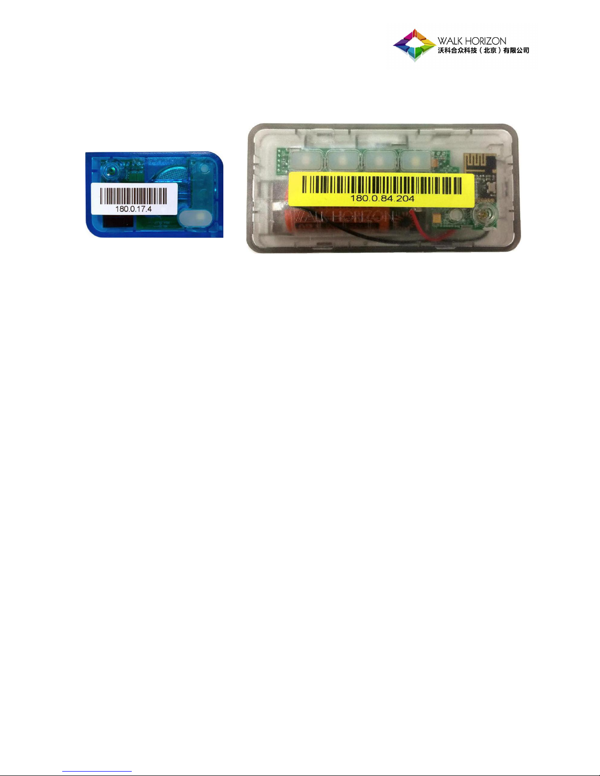
RFID Tag Tag-RRL100 & Tag-DRL100
Tag-DRL100
Tag-RRL100
The two sorts of active RFID tags are specified to provide RFID technology supported interactive
functions, which includes:
Private encryption protocol enforced wireless transmission to a RFID reader through long
distance;
Receiving encrypted wireless signals from a RFID reader;
Switching on/off the lighting module controlled by receiving signals, thereby providing a visual
guiding function. A RRL tag has four lights in different colors, whilst a DRL tag has one in white;
Detecting the clicking of the button, and hence transmitting Feedback signal to a reader, which
can be seen as the trigger of certain IT functions;
Transmitting Heartbeat signal to a reader at a certain time interval as the indicator of its
operating status;
Features
1. Simultaneously operating without collision. A large group of tags can work within a limited area
with orchestration;
2. The tags support full duplex communication, transmission and receiving took place
simultaneously;
3. As active tags, Tag-RRL100 and Tag-DRL100 need batteries as their power supply; it is due to
their higher power consumption to support long distance transmission of wireless signals. For
the two types, their average total operating hours between recharges are 9 hours over 1.5 years
(self-discharge considered) or 240 hours (constant on);
4. The tag battery is monitored, and alert can be generated if the power level becomes
considerably low;

- 6 -
Target Usage Scenario
Light indicating under data center facility management scenario;
Vehicle indicating under car parking or manufacturing scenario;
Stored inventory indicating under warehousing scenario;
Exterior

- 7 -
Parameters
Communication Related
Recognition Distance
Omni-directional antennas: 50m in maximum;
Directional antennas: 200m in maximum
Transmission Power
3dbm
Receiving Sensitivity
-96dBm, high sensitivity
RF Communication
Speed/bit Rate
250 kbps
Radio Frequency
Transmitting frecuency: 2.460GHz; 2.440GHz.
Receiving frecuency: 2.450GHz;
Environmental & Common Physical
Light
LED
Tag-RRL100: 4 LEDs in Red, Green, Blue and White;
Tag-DRL100: 1 LED in White
Low Voltage Alert
Default local alert via an indicating light
Battery Life
9 hours over 1.5 years (self-discharge considered)
or 240 hours (constant on), heartbeat every 60 seconds
Battery
Tag-RRL100: ER18505M 3.6V, Replaceable
Tag-DRL100: CR2450 3.0V, Replaceable
Operating Temperature
Tag-RRL100: -35⁰C ~ 50⁰C;
Tag-DRL100: 0⁰C ~ 50⁰C
Storing Temperature
-20℃~85℃
Operating Voltage
Tag-RRL100: DC 3.6V;
Tag-DRL100: DC 3.0V
Operating Current
≤30 mA when operating;
≤10 μA when standby
Exterior Material
ABS, PC, inflammable
Size
Tag-RRL100: 95mm (length)*45mm (width)*24mm (thickness)
Tag-DRL100: 49mm (length)*30mm (width)*13mm (thickness)
Weight
Tag-RRL100: 0.08Kg;
Tag-DRL100: 0.02Kg

- 8 -
Common Failures & Addressing
Issue
Possible Reasons
Recovery
Low voltage alert
Low battery
Return to manufacturer.
No signal detected
Extremely low battery
Return to manufacturer.
Transmission module
failure
Return to manufacturer.
If above methods do not recover, please contact technical support.
System: Interaction between RFID Reader and Tag
1. A round of operation starts with the RFID reader receiving a Switch-on signal from the
backbone system via Ethernet (cable) . The reader then converts the instruction to wireless
signaling, and broadcasts it via antenna RF1.
2. All tags (both types) in the coverage of the reader will receive the signaling via their receiving
antennas; after deciphering and processing the signaling, each of the tags obtains its target tag
ID and compares the ID with its own unique ID in its chip (EPC zone). If a tag whose ID is same
as the target ID, it will determine itself as the target tag and then switch on the LED on itself.
3. If the button of a tag (both types) is clicked, the tag will send a encrypted Feedback signal to the
reader via its transmission module. The signal is called Feedback because it is expected to take
place after lighting up and is prepared for sending back to activate certain following operation.
4. The reader receives the Feedback signal, deciphers, processes and converts it into a message,
which will then be sent to the backbone system via Ethernet.
5. The two types of the tags transmit their own working status signal (Heartbeat) to certain
readers at a certain time interval via their transmission modules.
6. The reader receives the Heartbeat signal, deciphers, processes and converts it into a message,
which would then be sent to the backbone system via Ethernet.
7. The two types of tags are designed to support full duplex communication. Above
communication 2 and 3, 2 and 5 can be carried out simultaneously; whilst 3 (press the button)
and 5(periodic heartbeat) can be carried out successively at a very short time interval.

- 9 -
Walk Horizon Technology (Beijing) Co., Ltd. 2017
Address: Room 121, Building B1, Shouxindasha,
5 Jiangtai Road, Chaoyang District, Beijing, 100015,
China
Phone: (8610) 8208 8750
Web: www.walkhorizon.com
 Loading...