

OPERATOR'S MANUAL
AND
SAFETY INSTRUCTIONS
WITH INSPECTION AND MAINTENANCE INSTRUCTIONS
TURBOMILL 40B MAGNETIC
MACHINING CHUCK SERIES
ELECTROPERM CHUCKS
O.S. WALKER
Rockdale Street, Worcester, MA 01606 (508)-853-3232 FAX (508)-852-8649
3508 Glenridge Drive, Chino Hills, CA 91709 (909)-597-4785 FAX (909)-597-0581
901 Arvin Avenue, Stoney Creek, Ontario, L8E5N9 Canada (905)-643-3338
In Canada: 1-800-267-4678 FAX (905)-643-6111
www.walkermagnet.com
Email: info@walkermagnet.com
Never attempt to operate this chuck until you have read and understand this
OPERATOR’S MANUAL
O.S. WALKER Co. Inc., Turbomill Electroperm Chucks
DD15508M.doc Rev. ~, September 17, 2002


TABLE OF CONTENTS
1 INTRODUCTION...............................................................................................................................................................1-1
2 SAFETY INSTRUCTIONS................................................................................................................................................2-1
2.1 G
ENERAL SAFETY RULES
2.2 R
ECOGNIZE SAFETY INFORMATION
.............................................................................................................................................2-1
...............................................................................................................................2-2
2.2.1 Ways to Avoid a Reduction of Holding Capacity................................................................................................2-2
2.2.2 Additional Warnings ...........................................................................................................................................2-3
2.3 D
ESIGNATED PERSON
2.4 E
LECTRICAL GROUND
..................................................................................................................................................2-3
..................................................................................................................................................2-4
3 INSTALLATION INSTRUCTIONS FOR MOUNTING THE CHUCK................................................................................3-1
3.1 G
RINDING THE MOUNTING SURFACES OF RECTANGULAR CHUCKS
..................................................................................3-1
3.1.1 Connecting the Chuck........................................................................................................................................3-2
4 OPERATING INSTRUCTIONS.........................................................................................................................................4-1
4.1 S
YSTEM OPERATION
4.2 I
MPORTANT FACTS ABOUT MAGNETIC HOLDING
4.3 S
URFACE CONDITIONS
....................................................................................................................................................4-1
.............................................................................................................4-1
.................................................................................................................................................4-1
4.3.1 Magnetic Chuck Surface Condition....................................................................................................................4-1
4.3.2 Workpiece Surface Condition.............................................................................................................................4-2
4.3.3 Workpiece Thickness .........................................................................................................................................4-2
4.3.4 Portion of the Chuck Surface In Contact With the Workpiece ...........................................................................4-2
4.3.5 Workpiece Material.............................................................................................................................................4-2
4.4 G
UIDELINES FOR THE REDUCTION OF RATED HOLDING CAPACITY
4.5 T
HE BASICS OF MAGNETIC ATTRACTION
........................................................................................................................4-3
...................................................................................4-3
4.5.1 Principles of Magnetic Work Holding..................................................................................................................4-4
4.6 F
ORCES GENERATED BY MILLING
.................................................................................................................................4-5
4.6.1 Conventional Milling ...........................................................................................................................................4-5
4.6.2 Climb Milling.......................................................................................................................................................4-6
4.6.3 Face Milling ........................................................................................................................................................4-7
4.6.4 Edge Milling........................................................................................................................................................4-8
4.7 W
ORKPIECE BLOCKING
4.8 M
ILD STEEL POLE RISER
.................................................................................................................................................4-9
............................................................................................................................................4-12
4.8.1 How to Use Riser Blocks..................................................................................................................................4-13
5 INSPECTION AND MAINTENANCE INSTRUCTIONS ...................................................................................................5-1
5.1 D
AILY INSPECTION
5.2 R
EPLACEMENT PARTS LIST
.......................................................................................................................................................5-1
...........................................................................................................................................5-1
6 RETURN AND REPAIR INSTRUCTIONS........................................................................................................................6-1
O.S. WALKER Co. Inc., Turbomill Electroperm Chucks
i
DD15508M.doc Rev. ~, September 17, 2002

F
IGURE
F
IGURE
F
IGURE
F
IGURE
F
IGURE
F
IGURE
F
IGURE
F
IGURE
F
IGURE
F
IGURE
F
IGURE
F
IGURE
F
IGURE
F
IGURE
4-1 B
ASIC MAGNETICS
4-2 M
AGNETIC ATTRACTION
4-3 C
ONVENTIONAL MILLING
4-4 C
LIMB MILLING
4-5 F
ACE MILLING
4-6 E
DGE MILLING
4-7 B
LOCKING
4-8 B
LOCKING
4-9 B
LOCKING
4-10 F
IXED RISER
4-11 F
IXED RISER
4-12 A
DJUSTABLE RISER
4-13 S
LIDING
4-14 R
ISER ORIENTATION
............................................................................................................................................................4-9
..........................................................................................................................................................4-10
..........................................................................................................................................................4-11
& F
TABLE OF FIGURES
...............................................................................................................................................4-3
.......................................................................................................................................4-4
.......................................................................................................................................4-5
.....................................................................................................................................................4-6
......................................................................................................................................................4-7
.....................................................................................................................................................4-8
....................................................................................................................................................4-12
....................................................................................................................................................4-12
..........................................................................................................................................4-12
IXED POLE RISERS
........................................................................................................................................4-13
.........................................................................................................................4-13
O.S. WALKER Co. Inc., Turbomill Electroperm Chucks
ii
DD15508M.doc Rev. ~, September 17, 2002

1 INTRODUCTION
Thank you for purchasing this O. S. Walker, Inc. Chuck. If used and maintained properly, it should
serve you for many years. However, if installed and used improperly it can be rendered inefficient
and unsafe. Therefore, it is absolutely essential that anyone who uses this chuck and is
responsible for its application be trained on how to use it correctly.
Read this manual carefully to learn how to operate and maintain your chuck. Failure to do
so could result in serious injury, or even death, to yourself and others in the area.
This manual should be considered a permanent part of your chuck and should always be
available to all operators and remain with the chuck if it is re-sold.
NOTE: Before using chuck, record this data from the *nameplate for future use in
obtaining service.
MODEL NO._____________, PART NO._____________, SERIAL NO. __________
* information located on the terminal box end of the chuck body.
To request additional copies of this manual, call 1-800-962-4638 in the USA;
In Canada: 905-643-3338; In Europe: 31-4973-83835
O.S. WALKER Co. Inc., Turbomill Electroperm Chucks
1-1
DD15508M.doc Rev. ~, September 17, 2002
2 SAFETY INSTRUCTIONS
2.1 General Safety Rules
Danger always exists when using industrial holding equipment, especially if the equipment is
not being used properly or is poorly maintained. Because accidents and sever bodily injury or
death can result, special safety precautions apply to the installation, operation, inspection,
and maintenance of all holding equipment.
Following these simple rules can help to avoid accidents:
• Never attempt to operate your magnetic chuck until you read and understand this
operator's manual.
• Never disconnect a magnetic chuck from the control's DC power source while it is
energized! Electrical arcing will occur and may cause serious injury or death.
• Only qualified personnel shall make adjustments within the control while it is
energized!
• Never operate the chuck until it has been verified that a proper electrical ground
for the control and Chuck has been established.
• Never operate damaged or malfunctioning controls or magnetic chucks.
Remember, proper holding knowledge and techniques in the use of this equipment are the
responsibility of the operator. Be sure to read and understand the instructions and safety
warnings contained in this manual before using your chuck control and magnetic chuck.
If you do not understand everything in this manual contact O.S. Walker for assistance before
using the equipment.
CALL 1-800-W-MAGNET
(In Canada call 905-643-3338; In Europe 31-4973-83835)
O.S. WALKER Co. Inc., Turbomill Electroperm Chucks
IN THE USA
2-1
DD15508M.doc Rev. ~, September 17, 2002
2.2 Recognize Safety Information
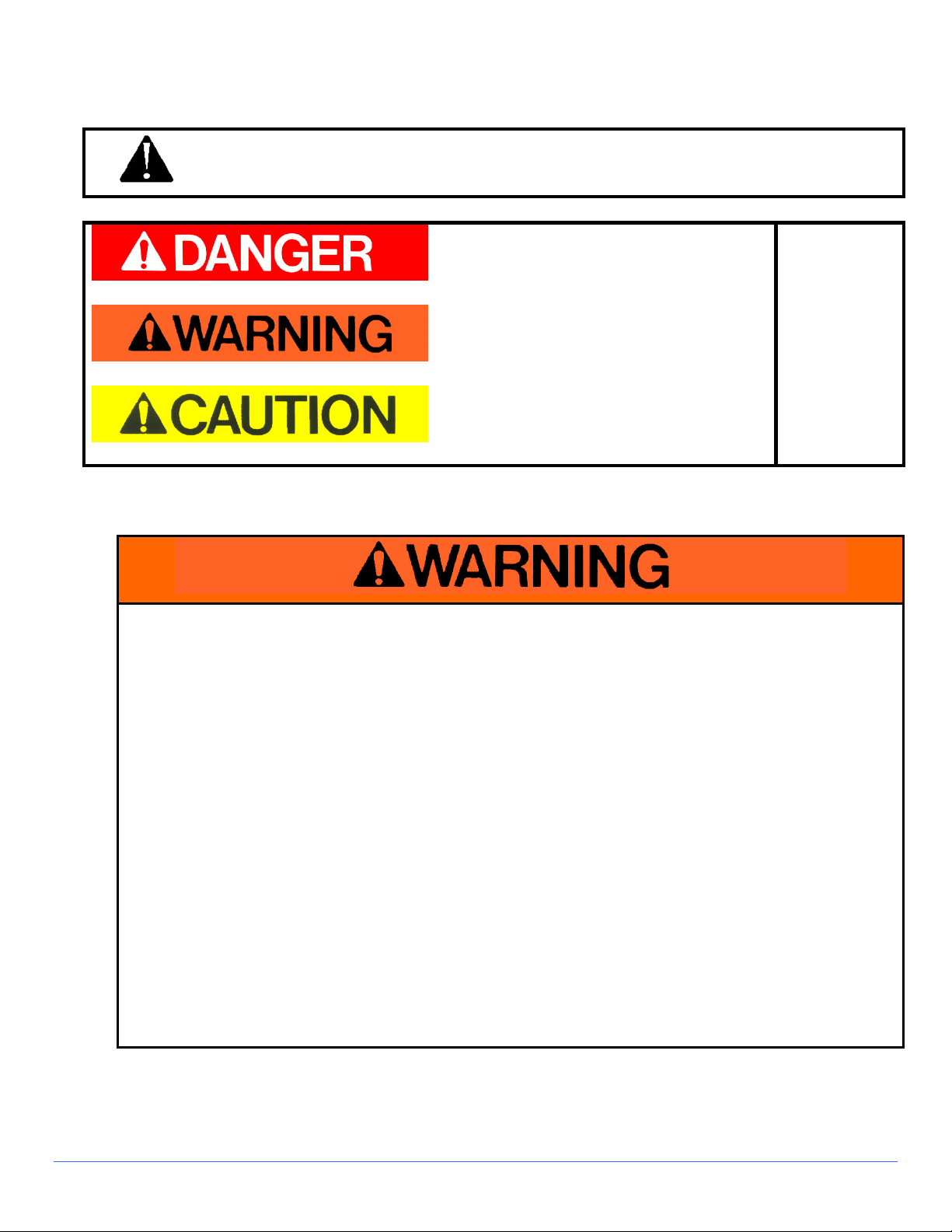
This is the safety alert symbol. When you see this symbol on your chuck or in this
manual, be alert to the potential for personal injury. Follow recommended
precautions and safe operating practices at all times.
This indicates a situation in which a hazard is
imminent and will result in a high probability of
serious injury or death.
Red Background, White Letters
This indicates a potentially hazardous
situation, which could result in some
probability of serious injury or death.
Orange Background, Black Letters
This indicates a potentially hazardous
situation, which could result in minor injury or
moderate injury.
Yellow Background, Black Letters
2.2.1 Ways to Avoid a Reduction of Holding Capacity
These are
Hazard
Seriousness
Signal
Words
To avoid any reduction of holding capacity:
• The holding surface of the chuck and the contact area of the workpiece where it will
contact the chuck must be clean, smooth, flat, and free of nicks and burrs
• The surface of the workpiece must contact equal areas of the chuck's opposite polarity,
major magnetic poles.
• The workpiece must be low carbon steel such as AISI 1020.
• The chuck control must provide "FULL" power to the chuck, that is, maximum output
voltage.
• The workpiece thickness must be at least equal or greater than the width of the chuck's
major magnetic poles.
• The temperature inside the chuck control enclosure must not be greater than 104º
Fahrenheit (40º Celsius), nor the temperature of the chuck must not be greater than 110º
F (43º C).
• Repair of this chuck control should only be done by the O. S. Walker Co.*
• If you have any difficulty holding a work piece, DON'T attempt to machine it! Call the O.S.
Walker Co. for advice at 1-800-962-4638.
O.S. WALKER Co. Inc., Turbomill Electroperm Chucks
2-2
DD15508M.doc Rev. ~, September 17, 2002
2.2.2 Additional Warnings
• Never operate damaged or
malfunctioning chuck.
• Never remove or damage Operating
and Warning labels.
• Persons using pacemakers or any
other medical devices should not use
this magnet until they have consulted
with their physician.
• The electrically conductive body of
this chuck must be connected to a
proper electrical ground.
2.3 Designated Person
*Walker replacement parts may be installed by a **Designated Person.
** Designated Person - A person selected or assigned by the employer as being competent
to replace specific replacement parts listed in this manual and is able to verify the proper
functioning of the specific replacement parts and the entire product after the completion of the
installation.
• Disassembly or repair of this chuck control can result in
reduced holding power and/or cause an unsafe
condition. Therefore, any time the control is
disassembled or repaired it should be thoroughly
inspected and re-tested for proper electrical grounding
and power output.
• Modification of any operating circuits and electrical
safety grounding can reduce the chuck control's
effectiveness and/or cause an unsafe condition.
• Repair or modification of this chuck should only be
done by O.S. Walker*.
O.S. WALKER Co. Inc., Turbomill Electroperm Chucks
2-3
DD15508M.doc Rev. ~, September 17, 2002

2.4 Electrical Ground
ELECTRICAL GROUNDING
Because the O. S. Walker Co. does not know the specifics of each application and installation of
these products and the electromagnetic device to which they are attached, it can only warn the
installer and user that the electrically conductive body of the electromagnetic device MUST be
connected to a proper electrical ground.
According to ANSI/NFPA 79 1997(an American National Standard) "Electrical Standard for
Industrial Machinery":
• Section 19.3 Equipment Grounding: The machine and all exposed noncurrent-carrying
conductive parts, material, and equipment, including metal mounting panels that are likely to
become energized and are mounted in nonmetallic enclosures, shall be effectively grounded.
• Section 19.2.4 Grounding Conductors: It shall be permissible to use machine members or
structural parts of the electrical equipment in the grounding circuit provided that the crosssectional area of these parts is at least electrically equivalent to the minimum cross-sectional
area of the copper conductor required.
• Section 19.6.1 Continuity of the Grounding Circuit: The continuity of the grounding circuit
shall be ensured by effective connections through conductors or structural members.
• Section 19.6.3 Continuity of the Grounding Circuit: Moving machine parts, other than
accessories or attachments, having metal-to-metal bearing surfaces shall be considered as
bonded. Sliding parts separated by a non-conductive fluid under pressure shall not be
considered as bonded.
PRIOR TO ENERGIZING THE ELECTROMAGNETIC DEVICE, CHECK ALL THE ELECTRICAL
CONNECTIONS AND CONFIRM THAT THE METAL BODY OF THE ELECTROMAGNETIC
DEVICE IS ELECTRICALLY GROUNDED.
O.S. WALKER Co. Inc., Turbomill Electroperm Chucks
2-4
DD15508M.doc Rev. ~, September 17, 2002

3 INSTALLATION INSTRUCTIONS FOR MOUNTING THE CHUCK
3.1 Grinding the Mounting Surfaces of Rectangular Chucks
A) Clean and degrease magnetic chuck. Soak chuck with WD-40 and let sit for 15 minutes to
remove kosmolene. (Protective Coating)
B) Check bottom surface for sharp edges or burrs. Use file or oil stone to remove them.
C) Clean the machine's table surface and place the chuck, face down, on the sliding table of
a surface grinder and indicate the surface of the chuck lengthwise and crosswise. Shim
as necessary to level the surface to be ground.
D) Loosely clamp or block each end of the chuck to the table so as not to distort the chuck
and to prevent the chuck from moving while being ground. DO NOT HOLD IN PLACE BY
ENERGIZING THE CHUCK.
E) Grind the bottom surface with a roughly dressed grinding wheel using a general-purpose
medium hardness 36 - 40 grit type-grinding wheel. Wet grind using a semi synthetic,
synthetic, or oil-base coolant.
F) Depth of cut can vary dependant on machine size and wheel type, consult machine
manual or grinding wheel manufacturer.
G) Cross feed-half wheel width per pass dependant on machine and wheel size, consult
machine manual.
H) Table speed should be set at about 75 feet per minute dependant on machine and wheel
size, consult machine manual.
I) Grind to clean bottom of chuck. DO NOT DRY GRIND THE CHUCK.
J) After the base surface has been ground flat, remove the chuck, clean, and dry the
mounting area of the table. Be sure to clean thoroughly freeing from all burrs before
mounting in the normal upright position. Apply a thin coat of light oil to the table surface.
K) Place the chuck on the table with the holding surface up.
L) The clamps provided with rectangular type chucks should initially be tightened only
enough to prevent the chuck from moving. Then the chuck should be aligned with the
table and the clamp bolts gradually tightened in an alternating sequence to a torque of 10
foot-pounds. Then only the bolts on one end of the chuck should be tightened to 15 foot-
pounds. This will allow for expansion without distortion along the chuck length as the
chuck and machine reach their normal operating temperature.
M) At this time, electromagnetic chucks can be turned on and allowed to stabilize at the
"median" temperature of the machine. Normal coolant flow should be used during this
period. Electro-perm magnetic chucks do not contribute heat, but also require a
stabilization to reach the "median" temperature of the machine.
N) Finish grind the surface of the chuck to be assured it is in alignment with the machine axis
following steps E. thru I. for best results.
O.S. WALKER Co. Inc., Turbomill Electroperm Chucks
3-1
DD15508M.doc Rev. ~, September 17, 2002

3.1.1 Connecting the Chuck
The DC output to the chuck must include a ground wire that is connected to the safety
ground lug on the chuck and to the chassis of the chuck control. It is recommended that
the conduit for the DC output not be routed near high voltage AC wires. Many chucks
are installed on machines with moving tables. Choose a means of wiring the chuck that
allows adequate freedom of movement over the full range of table travel.
O.S. WALKER Co. Inc., Turbomill Electroperm Chucks
3-2
DD15508M.doc Rev. ~, September 17, 2002

4 OPERATING INSTRUCTIONS
4.1 System Operation
The electro-perm chucks operate via a chuck control. The control for this particular
Electroperm chuck should be either a Walker VFR-10 or a Walker Smart 100T control. You
can refer to the chuck control manual for detailed information on the installation and
operation of this control. Use of other model controls could result in reduced holding force or
cause permanent damage to the chuck.
The basic on/off sequence of operation of the chuck is by depressing the "ON" or "OFF"
button on the remote station of the control. Electroperm chucks can be unplugged once the
cycle is complete.
Always be sure the work piece is completely resting on the top surface of the chuck before
turning the chuck "ON". Also, use caution when handling metal objects near the top surface
of the chuck when it is "ON". The permanent magnetic field can cause these objects to be
attracted to the chuck.
4.2 Important Facts about Magnetic Holding
Work piece characteristics must be considered in order to determine the magnetic holding
attraction that a magnetic chuck can provide.
This is true for all magnetic chucks because they all operate using the same fundamental
laws of physics. Magnetic power is often pictured as lines of magnetic force flowing from
north to south pole. Anything that limits the flow of these magnetic lines of force obviously
reduces the magnets holding capacity. Many important factors limit the flow of these lines of
force.
4.3 Surface Conditions
Magnetic lines of force do not flow easily through air. They need iron in order to flow freely;
therefore, anything that creates a space or an air gap between the magnet and the work
piece limits the flow of magnetic lines of force and, thus, reduces the holding capacity of a
magnetic chuck.
4.3.1 Magnetic Chuck Surface Condition
The holding surface of a magnetic chuck must be clean, smooth, flat, and free of nicks or
burrs in order to minimize the air gap between the chuck holding surface and the Work
piece. All Walker chucks are designed with soft, low carbon steel magnetic poles in the
chuck in order to maximize the holding capacity; therefore, special care must be taken to
protect these areas.
O.S. WALKER Co. Inc., Turbomill Electroperm Chucks
4-1
DD15508M.doc Rev. ~, September 17, 2002

4.3.2 Workpiece Surface Condition
The holding capacity of the chuck will be reduced if certain surface conditions exist. A
rough surface finish on the work piece creates an air gap. Foreign materials such as dirt,
paint, rust, paper, and rags will create an air gap.
4.3.3 Workpiece Thickness
The greater the number of lines of magnetic force flowing from a magnet into the work
piece the greater the effectiveness of the magnetic chuck. The thicker the work piece,
the more lines of magnetic force are able to flow. After a certain thickness of the work
piece, no additional lines of force will flow because the magnet has reached its full
capacity.
Thin work pieces mean less iron available, and thus fewer lines of magnetic force flow
from the magnet into the work piece. Therefore, the chuck holding capacity is reduced.
Typically, the minimum thickness of a work piece required to reach full holding capacity
is the same as the thickness of the chuck major magnetic steel poles.
4.3.4 Portion of the Chuck Surface In Contact With the Workpiece
The full surface of the chuck top plate must be covered by the work piece to achieve the
maximum holding capacity. The surface of the work piece must contact equal areas of
the chuck opposite polarity major magnetic poles to obtain maximum holding force.
4.3.5 Workpiece Material
Low carbon steel such as SAE 1020 steel, are nearly as good conductors of magnetic
lines of force as pure iron. However, many other alloys contain non-magnetic materials,
which reduce the ability of magnetic lines of force to flow. An alloy such as SAE 300
series stainless steel is almost as poor a conductor of magnetic lines of force as air.
Type 416 stainless steel is considered magnetic, but it contains enough chromium so
that a magnet can develop only about one half as much magnetic force as it can on an
SAE 1020 steel work piece. In addition, because of the carbon content, the force
developed on typical cast iron is less than one half that developed on SAE 1020 steel.
(Chilled cast iron further reduces the force to less than one quarter.)
Additional concerns regarding Magnetic Holding should be forwarded to O. S. Walker,
Inc.
O.S. WALKER Co. Inc., Turbomill Electroperm Chucks
4-2
DD15508M.doc Rev. ~, September 17, 2002

4.4 Guidelines for the Reduction of Rated Holding Capacity
Each Walker chuck model is rated for different holding limits. Load characteristics will affect
the holding capacity of the chuck. The holding guidelines for the chuck models are shown
below.
THIS TABLE PROVIDES SOME REDUCTION FACTORS FOR MATERIAL OTHER THAN
SAE 1020 STEEL.
Table 4-1 Reduction Factor for material other than SAE 1020 Steel
Reduction factors for material other than SAE 1020 Steel
Materials Reduction Factor
Cast Steel 0.90
3% Silicon Steel 0.80
SAE 1095 Steel 0.70
416 Stainless Steel 0.50
Cast Iron (non-chilled) 0.45
Pure Nickel 0.10
For other materials, contact O.S. Walker
4.5 The Basics of Magnetic Attraction
Magnetic lines of force (flux) exist between the north and south poles of a magnet.
Figure 4-1 Basic Magnetics
This flux can be used to attract and hold ferrous components, which when placed in a flux
field have poles induced in them of opposite polarity to the magnet. These are attracted to
the magnet until contact occurs. As the ferrous parts get closer to the magnet, more flux lines
are induced into the work, as the distance decrease and flux lines increase, the holding force
increases until contact is made and the maximum force is achieved.
O.S. WALKER Co. Inc., Turbomill Electroperm Chucks
4-3
DD15508M.doc Rev. ~, September 17, 2002

Figure 4-2 Magnetic Attraction
4.5.1 Principles of Magnetic Work Holding
The ability to hold a work piece magnetically on a milling chuck is dependent on the
characteristics of the work piece itself and, of course, the degree of machine force
exerted upon it.
To establish the feasibility of a specific application, three key parameters must be
considered.
1) Work Piece Material
As a rule, though there are some exceptions, magnetic conductivity in a material
decreases with greater alloy content. Mild steel is more conductive than tool steel,
which is more conductive than cast iron, and so on.
2) Work Piece Contact Surface
Any condition that creates a non-magnetic gap between the chuck and the work
piece will reduce holding force. Rust, scale, weld spatter, shims; warped pieces can
all contribute to reduced holding. The greater the air gap in a magnetic circuit, the
more inefficient it is. Therefore, hold down force increases with flatter contact
surfaces.
3) Work Piece Contact Area
Hold down pulling force is measured in lbs/sq. inch Therefore; increased contact
area will ultimately increase hold down force.
O.S. WALKER Co. Inc., Turbomill Electroperm Chucks
4-4
DD15508M.doc Rev. ~, September 17, 2002

4.6 Forces Generated by Milling
Turbo-mill milling chucks can generate up to 5 tons/ft² holding force, so it is very unlikely that
a work piece will lift away from the holding surface of the chuck. However, the resistance
force to horizontal sideways movement is approximately four to five times less than the
downward holding force. Consequently, if the cutting forces exceed the chuck’s resistance
force to horizontal sideways movement, the work piece will slide in the direction of the forces.
Therefore, when it is feasible, it is strongly recommended to use side and end stops. The
side and end stops will provide added support to resist the forces generated by the cutting
tool in conventional, climb, face, and edge milling applications. (See pages 4-5, 4-6, 4-7, 4-8,
4-9, 4-10, & 4-11)
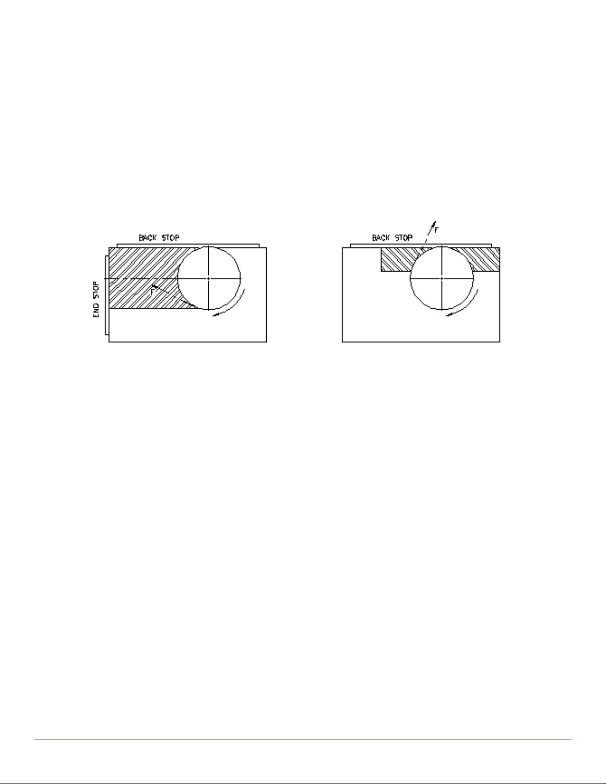
4.6.1 Conventional Milling
The cutter tries to pull the work up and push it along the chuck. The machining force is F
tangential to the cutter its horizontal component FH is resisted by the end stop to the left,
and the friction between the work piece and chuck face. The vertical component FV is
resisted by the downward pull of the chuck.
O.S. WALKER Co. Inc., Turbomill Electroperm Chucks
Figure 4-3 Conventional Milling
4-5
DD15508M.doc Rev. ~, September 17, 2002

4.6.2 Climb Milling
The machining force F is downward toward the chuck and to the bottom right hand
corner of the work piece. Therefore, the end stop is placed at the end where the cut
starts. As the cut proceeds, the machining force helps to hold the work piece down onto
the chuck face. This means that heavier cuts can be taken in climb milling.
Figure 4-4 Climb Milling
O.S. WALKER Co. Inc., Turbomill Electroperm Chucks
4-6
DD15508M.doc Rev. ~, September 17, 2002
4.6.3 Face Milling
For on-center face milling, the action of the cutter tends to push the work up to the left
hand end and to the side of the chuck because the center of the cutter is over the center
of the work pieces. This condition cannot always be met, however, and it is sometimes
necessary to position the work piece off-center in relation to the cutter. For off-center
milling, the work piece is still pushed to the same side but towards the end stop on the
right.
Figure 4-5 Face Milling
O.S. WALKER Co. Inc., Turbomill Electroperm Chucks
4-7
DD15508M.doc Rev. ~, September 17, 2002

4.6.4 Edge Milling
In all cases, when the chuck is working to full capacity, it is better to climb mill the work
piece into the side and end stops. However, the centerline of the cutter in relation to the
edge of the work piece will have an adverse affect to the ultimate direction of the force
exerted to the work piece.
Note that the workpiece entry force and exit force directions are different. Therefore, for
vertical edge milling, the cutting depth recommended limit is half the diameter of the
cutter.
Figure 4-6 Edge Milling
Note that the workpiece entry force and exit force directions are different. Therefore, for vertical
edge milling, the cutting depth recommended limit is half the diameter of the cutter.
O.S. WALKER Co. Inc., Turbomill Electroperm Chucks
4-8
DD15508M.doc Rev. ~, September 17, 2002

4.7 Workpiece Blocking
Using Walker's heavy duty milling chuck, the smallest work piece to be held on the magnet
should be at least 4" x 7-1/2". Smaller pieces will need blocking.
O.S. WALKER Co. Inc., Turbomill Electroperm Chucks
Figure 4-7 Blocking
4-9
DD15508M.doc Rev. ~, September 17, 2002

O.S. WALKER Co. Inc., Turbomill Electroperm Chucks
Figure 4-8 Blocking
4-10
DD15508M.doc Rev. ~, September 17, 2002

Another option for smaller pieces would be to put them in a vise and put the vise on the
magnet to machine the part.
Call O.S. Walker and fax part size for help with difficult to hold work pieces. We will assist with
proper blocking details.
O.S. WALKER Co. Inc., Turbomill Electroperm Chucks
Figure 4-9 Blocking
4-11
DD15508M.doc Rev. ~, September 17, 2002

4.8 Mild Steel Pole Riser
Pole extensions are probably the most important and versatile pieces of tooling that can be
used on O.S.W. milling chuck.
We recommended that several sets of different heights be produced for your chuck as
accessory tooling.
Pole risers are useful for several reasons:
1) Locating surfaces for repeat operations.
2) Raise work for boring through operations.
3) Raise work up for access to sides.
Figure 4-10 Fixed Riser
O.S. Walker can provide pole risers to meet your requirements. O. S. Walker recommends
that pole risers be machined from 1020 mild steel.
O.S. WALKER Co. Inc., Turbomill Electroperm Chucks
Figure 4-11 Fixed Riser
Figure 4-12 Adjustable Riser
4-12
DD15508M.doc Rev. ~, September 17, 2002

Figure 4-13 Sliding & Fixed Pole Risers
4.8.1 How to Use Riser Blocks
Each setup situation is unique and cannot be covered in this manual. The following are
general guidelines for the use of riser blocks, fixed and adjustable.
The workpiece should be supported at three points with fixed riser blocks, either
individual or groups.
The entire surface under the workpiece should be supported with adjustable riser blocks.
When the adjustable riser blocks are positioned under the work piece, orient the blocks
as shown in Figure 4-14.
O.S. WALKER Co. Inc., Turbomill Electroperm Chucks
Figure 4-14 Riser Orientation
4-13
DD15508M.doc Rev. ~, September 17, 2002

5 INSPECTION AND MAINTENANCE INSTRUCTIONS
5.1 Daily Inspection
• Inspect the holding surface of your magnetic chuck. It must be clean, smooth, flat, and free
of nicks or burrs in order to minimize the air gap between the chuck holding surface and the
Work piece. All Walker chucks are designed with soft, low carbon steel magnetic poles in
the chuck in order to maximize the holding capacity; therefore, special care must be taken
to protect these areas. Regrind when necessary (see section 3.1)
• The cord must be free of nicks and cuts. Replace if damaged.
• Inspect the receptacle for damage or wear. Make necessary repairs.
• Perform an overall inspection of the chuck for wear or damage and correct any
deficiencies.
5.2 Replacement Parts List
• Electrical receptacle
• Cord
• Clamps
• Rails
• Risers
Contact O.S, Walker for specific part numbers for your model chuck.
O.S. WALKER Co. Inc., Turbomill Electroperm Chucks
5-1
DD15508M.doc Rev. ~, September 17, 2002

6 RETURN AND REPAIR INSTRUCTIONS
For warranty and non-warranty repairs on any part of your chuck system, contact O.S. Walker, Inc.
TOLL FREE at 1-800-W-MAGNET. A return authorization number will be issued along with any
applicable packaging and shipping instructions. After receipt of the components to be repaired,
O.S. Walker, Inc. will perform an inspection and provide an estimate of the repair costs at no
charge to the customer. Authorization from the customer must be obtained by O.S. Walker, Inc.
before repairs are made. Transportation charges, both to and from the factory, are the sole
responsibility of the customer.
FOR FAST RESPONSE, CALL 1-800-W-MAGNET
O.S. WALKER Co. Inc., Turbomill Electroperm Chucks
O.S. WALKER
Rockdale Street, Worcester, MA 01606
(508)-853-3232 FAX (508)-852-8649
3508 Glenridge Drive, Chino Hills, CA 91709
(909)-597-4785 FAX (909)-597-0581
901 Arvin Avenue, Stoney Creek, Ontario, L8E5N9 Canada
(905)-643-3338
In Canada: 1-800-267-4678 FAX (905)-643-6111
www.walkermagnet.com
e-mail: info@walkermagnet
DD15508M.doc Rev. ~, September 17, 2002
 Loading...