


OPERATOR'S MANUAL
AND
SAFETY INSTRUCTIONS
WITH INSTALLATION, TROUBLESHOOTING,
INSPECTION AND MAINTENANCE INSTRUCTIONS
SMART-D SERIES
Microprocessor Controlled
Chuck Control
O.S. WALKER
Rockdale Street, Worcester, MA 01606 (508)-853-3232 FAX (508)-852-8649
3508 Glenridge Drive, Chino Hills, CA 91709 (909)-597-4785 FAX (909)-597 -0581
901 Arvin Avenue, Stoney Creek, Ontario, L8E5N9 Canada (905)-643-3338
In Canada: 1-800-267-4678 FAX (905)-643-6111
www.walkermagnet.com
Email: info@walkermagnet.com
Never attempt to operate this control until you have read
and understand this OPERATOR'S MANUAL
O.S. WALKER Co., Inc. SMART-D Control
SMART D MANUAL DD14511L Rev. L, March 30, 2011

O.S. WALKER Co., Inc. SMART-D Control
SMART D MANUAL DD14511L Rev. L, March 30, 2011

TABLE OF CONTENTS
1 INTRODUCTION...............................................................................................................................................................1-1
2 SAFETY INSTRUCTIONS................................................................................................................................................2-1
2.1 GENERAL SAFETY RULES .............................................................................................................................................2-1
2.2 RECOGNIZE SAFETY INFORMATION................................................................................................................................2-2
2.2.1 Ways to Avoid a Reduction of Holding Capacity................................................................................................2-2
2.3 ADDITIONAL WARNINGS................................................................................................................................................2-3
2.4 DESIGNATED PERSON ..................................................................................................................................................2-3
3 INSTALLATION INSTRUCTIONS....................................................................................................................................3-1
3.1 MOUNTING THE CHUCK CONTROL & CONNECTING ELECTRICAL POWER..........................................................................3-1
3.1.1 Optional Remote Unit.........................................................................................................................................3-1
3.1.2 Main Chuck Control Unit ....................................................................................................................................3-1
3.1.3 Connecting the Chuck........................................................................................................................................3-2
3.1.4 Connecting the AC Input voltage........................................................................................................................3-2
3.1.5 575 Volt Controllers............................................................................................................................................3-2
3.1.6 Transformer Wiring Diagram..............................................................................................................................3-3
3.1.7 Connecting Optional Features............................................................................................................................3-4
3.1.8 Current Sensing..................................................................................................................................................3-4
3.1.9 Part Release.......................................................................................................................................................3-4
3.1.10 Lockout.............................................................................................................................................................3-4
3.1.11 Energizing the System .....................................................................................................................................3-4
3.2 CONTROL MOUNTING GUIDELINES ................................................................................................................................3-5
4 OPERATING INSTRUCTIONS.........................................................................................................................................4-1
4.1 IMPORTANT FACTS ABOUT MAGNETIC HOLDING .............................................................................................................4-1
4.1.1 Surface Conditions.............................................................................................................................................4-1
4.1.2 Workpiece Thickness.........................................................................................................................................4-2
4.1.3 Portion of the Chuck Surface In Contact With the Workpiece ...........................................................................4-2
4.1.4 Workpiece Material.............................................................................................................................................4-2
4.2 FULL HOLDING .............................................................................................................................................................4-3
4.3 VARIABLE HOLDING......................................................................................................................................................4-3
4.4 RESIDUAL HOLDING......................................................................................................................................................4-3
4.5 RELEASE .....................................................................................................................................................................4-3
4.6 CONTROL PROTECTION ................................................................................................................................................4-5
4.7 RELEASE CYCLE STEPS................................................................................................................................................4-5
4.8 GROUNDING & SHIELDING.............................................................................................................................................4-7
4.8.1 Current Sensing..................................................................................................................................................4-7
4.8.2 Part Release.......................................................................................................................................................4-7
4.8.3 Lockout...............................................................................................................................................................4-7
4.9 CONTROL OUTPUT VOLTAGE ........................................................................................................................................4-7
5 MAINTENANCE & TROUBLESHOOTING......................................................................................................................5-1
5.1 INSPECTION & MAINTENANCE........................................................................................................................................5-1
5.2 HAVING A PROBLEM WITH YOUR CHUCK CONTROL?.......................................................................................................5-1
5.3 CHUCK CONTROL CONNECTIONS ..................................................................................................................................5-3
5.4 REMOTE INTERFACE.....................................................................................................................................................5-4
5.4.1 Connections:.......................................................................................................................................................5-4
5.5 INTERFACE...................................................................................................................................................................5-4
5.6 SMART 75/100D PANEL LAYOUT...................................................................................................................................5-5
5.7 SMART 20/30/50D PANEL LAYOUT................................................................................................................................5-6
5.8 SMART 7/10/15D PANEL LAYOUT..................................................................................................................................5-7
5.9 SMART 3/5D PANEL LAYOUT.........................................................................................................................................5-8
5.10 MAIN PC BOARD........................................................................................................................................................5-9
5.11 SMART 75/100D WIRING..........................................................................................................................................5-10
5.12 SMART 20/30/50D WIRING.......................................................................................................................................5-11
O.S. WALKER Co., Inc. SMART-D Control
ii
SMART D MANUAL DD14511L Rev. L, March 30, 2011

SMART 7/10/15D 115V WIRING................................................................................................................................5-12
5.13
5.14 SMART 7/10/15D 200V WIRING................................................................................................................................5-13
5.15 SMART 3/5D 115VDC WIRING .................................................................................................................................5-14
5.1 SMART 3/5D 230VDC WIRING ...................................................................................................................................5-15
5.2 ENCLOSURE DIMENSIONS FOR SMART-D CONTROLS .................................................................................................5-16
5.3 REMOTE ENCLOSURE DIMENSIONS .............................................................................................................................5-17
5.4 REMOTE WIRING CONNECTIONS .................................................................................................................................5-18
5.5 REPLACEMENT PARTS LIST.........................................................................................................................................5-19
6 RETURN AND REPAIR INSTRUCTIONS........................................................................................................................6-1
TABLE OF TABLES
TABLE 5-1 TERMINAL TB1 ......................................................................................................................................................5-3
TABLE 5-2 CONNECTOR - J4...................................................................................................................................................5-3
TABLE 5-3 CONNECTOR - J5...................................................................................................................................................5-3
TABLE 5-4 REMOTE TB = TBR (LOCATED IN REMOTE ENCLOSURE); J5 (LOCATED ON MAIN PC BOARD) ......................................5-4
TABLE 5-5 REPLACEMENT PARTS..........................................................................................................................................5-19
TABLE OF FIGURES
FIGURE 3-1 CHUCK CONTROL ENCLOSURE..............................................................................................................................3-2
FIGURE 3-2 TRANSFORMER WIRING DIAGRAM .........................................................................................................................3-3
FIGURE 4-1 RELEASE CYCLE VOLTAGE VS. RELEASE CYCLE TIME...........................................................................................4-6
FIGURE 5-1 SMART 75/100D PANEL .......................................................................................................................................5-5
FIGURE 5-2 SMART 20/30/50D PANEL ....................................................................................................................................5-6
FIGURE 5-3 SMART 7/10/15D PANEL ......................................................................................................................................5-7
FIGURE 5-4 SMART 3/5D PANEL .............................................................................................................................................5-8
FIGURE 5-5 MAIN PC BOARD..................................................................................................................................................5-9
FIGURE 5-6 SMART 75/100D WIRING....................................................................................................................................5-10
FIGURE 5-7 SMART 20/30/50D WIRING.................................................................................................................................5-11
FIGURE 5-8 SMART 7/10/15D 115V WIRING..........................................................................................................................5-12
FIGURE 5-9 SMART 7/10/15D 230V WIRING..........................................................................................................................5-13
FIGURE 5-10 SMART 3/5D 115VDC WIRING .........................................................................................................................5-14
FIGURE 5-11 SMART 3/5D 230VDC WIRING .........................................................................................................................5-15
FIGURE 5-11 REMOTE ENCLOSURE BB-8783........................................................................................................................5-17
FIGURE 5-12 REMOTE WIRING CONNECTIONS .......................................................................................................................5-18
O.S. WALKER Co., Inc. SMART-D Control
iii
SMART D MANUAL DD14511L Rev. L, March 30, 2011

1 INTRODUCTION
Thank you for purchasing this O.S. Walker Chuck Control. If used and maintained properly, it
should serve you for many years. However, if installed and used improperly, it can be rendered
inefficient and unsafe. Therefore, it is absolutely essential that anyone who uses this control or is
responsible for its application be trained on how to use it correctly.
Read this manual carefully to learn how to operate and maintain your chuck control. Failure
to do so could result in serious injury, or even death, to yourself and others.
This manual should be considered a permanent part of your control and should always be
available to all operators and remain with the control if it is re-sold.
NOTE: Before using chuck control, record this data from the nameplate for future use in
obtaining service.
MODEL NO._____________, PART NO._____________, SERIAL NO. __________
To request additional copies of this manual, call 1-800-962-4638 in the USA;
In Canada: 905-643-3338; In Europe: 31-4973-83835
O.S. WALKER Co., Inc. SMART-D Control
1-1
SMART D MANUAL DD14511L Rev. L, March 30, 2011
2 SAFETY INSTRUCTIONS
2.1 General Safety Rules
Following these simple rules can help to avoid accidents:
• Never attempt to operate this control and your magnetic chuck until you read and
understand this operator's manual.
• Never disconnect a magnetic chuck from the control's DC power source while it is
energized! Electrical arcing will occur and may cause serious injury or death.
• Only qualified personnel shall make adjustments within the control while it is energized!
• Never operate the control and chuck until it has been verified that a proper electrical
ground for the control and Chuck has been established.
• Never perform any machining of work pieces on the magnetic chuck with the control
setting in the "Residual" mode.
• Never operate damaged or malfunctioning controls or magnetic chucks.
Remember, proper knowledge and techniques in the use of this equipment are the
responsibility of the operator. Be sure to read and understand the instructions and safety
warnings contained in this manual before using your chuck control and magnetic chuck.
If you do not understand everything in this manual contact O.S. Walker for assistance before
using the equipment.
(In Canada call 905-643-3338; In Europe 31-4973-83835)
O.S. WALKER Co., Inc. SMART-D Control
CALL 1-800-W-MAGNET IN THE USA
2-1
SMART D MANUAL DD14511L Rev. L, March 30, 2011
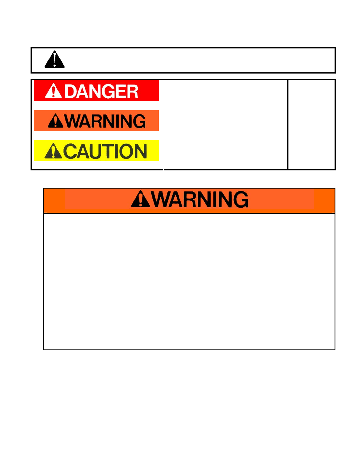
2.2 Recognize Safety Information
This is the safety alert symbol. When you see this symbol on your magnet or in
this manual, be alert to the potential for personal injury. Follow recommended
precautions and safe operating practices at all times.
This indicates a situation in which a hazard is
imminent and will result in a high probability of
serious injury or death.
Red Background, White Letters
This indicates a potentially hazardous
situation, which could result in some
probability of serious injury or death.
Orange Background, Black Letters
This indicates a potentially hazardous
situation, which could result in minor injury or
moderate injury.
Yellow Background, Black Letters
2.2.1 Ways to Avoid a Reduction of Holding Capacity
These are
Hazard
Seriousness
Signal
Words
To avoid any reduction of holding capacity:
• The holding surface of the chuck and the contact area of the workpiece where it will
contact the chuck must be clean, smooth, flat, and free of nicks and burrs.
• The surface of the workpiece must contact equal areas of the chuck's opposite polarity,
major magnetic poles.
• The workpiece must be low carbon steel such as AISI 1020.
• The chuck control must provide "FULL" power to the chuck, that is, maximum output
voltage.
• The workpiece thickness must be at least equal or greater than the width of the chuck's
major magnetic poles.
• The temperature inside the chuck control enclosure must not be greater than 104°
Fahrenheit (40° Celsius), nor the temperature of the chuck must not be greater than 110°
F (43° C).
• Repair of this chuck control should only be done by the O. S. Walker Co.*
• If you have any difficulty holding a work piece, DON'T attempt to machine it! Call the O.S.
Walker Co. for advice at 1-800-962-4638.
O.S. WALKER Co., Inc. SMART-D Control
2-2
SMART D MANUAL DD14511L Rev. L, March 30, 2011

2.3 Additional Warnings
• Disassembly or repair of this chuck control can result in reduced holding power and/or
cause an unsafe condition. Therefore, any time the control is disassembled or repaired it
should be thoroughly inspected and re-tested for proper electrical grounding and power
output.
• Modification of any operating circuits and electrical safety grounding can reduce the chuck
control's effectiveness and/or cause an unsafe condition.
• Repair of this chuck control should only be done by the O. S. Walker Co.*
2.4 Designated Person
*Walker replacement parts may be installed by a **Designated Person.
** Designated Person - A person selected or assigned by the employer as being competent
to replace specific replacement parts listed in this manual and is able to verify the proper
functioning of the specific replacement parts and the entire product after the completion of the
installation.
O.S. WALKER Co., Inc. SMART-D Control
2-3
SMART D MANUAL DD14511L Rev. L, March 30, 2011

ELECTRICAL GROUNDING
Because the O. S. Walker Co. does not know the specifics of each application and installation of
these products and the electromagnetic device to which they are attached, it can only warn the
installer and user that the electrically conductive body of the electromagnetic device MUST be
connected to a proper electrical ground.
According to ANSI/NFPA 79 1997(an American National Standard) "Electrical Standard for
Industrial Machinery":
• Section 19.3 Equipment Grounding: The machine and all exposed noncurrent-carrying
conductive parts, material, and equipment, including metal mounting panels that are likely to
become energized and are mounted in nonmetallic enclosures, shall be effectively grounded.
• Section 19.2.4 Grounding Conductors: It shall be permissible to use machine members or
structural parts of the electrical equipment in the grounding circuit provided that the crosssectional area of these parts is at least electrically equivalent to the minimum cross-sectional
area of the copper conductor required.
• Section 19.6.1 Continuity of the Grounding Circuit: The continuity of the grounding circuit shall
be ensured by effective connections through conductors or structural members.
• Section 19.6.3 Continuity of the Grounding Circuit: Moving machine parts, other than
accessories or attachments, having metal-to-metal bearing surfaces shall be considered as
bonded. Sliding parts separated by a non-conductive fluid under pressure shall not be
considered as bonded.
PRIOR TO ENERGIZING THE ELECTROMAGNETIC DEVICE, CHECK ALL THE ELECTRICAL
CONNECTIONS AND CONFIRM THAT THE METAL BODY OF THE ELECTROMAGNETIC
DEVICE IS ELECTRICALLY GROUNDED.
O.S. WALKER Co., Inc. SMART-D Control
2-4
SMART D MANUAL DD14511L Rev. L, March 30, 2011

3 INSTALLATION INSTRUCTIONS
• All electrical chassis must be safety grounded.
• Check that all sources of power are disconnected locked out and tagged “Out of Service” prior
to beginning installation. Only qualified personnel should install this chuck control unit.
Prior to beginning, thoroughly plan your installation. Read this manual completely. The installation
parts list below should aid in your planning.
1. Mounting hardware for the control and the remote.
2. Conduit and associated hardware for AC input, chuck output and remote.
3. Remote cable: 14-conductor #22 AWG shielded cable.
4. Chuck cable: Type SO or SJO cord with proper current rating.
3.1 Mounting the Chuck Control & Connecting Electrical Power
3.1.1 Optional Remote Unit
Select a location for mounting the remote unit. The remote unit should be mounted in a
location that is both safe and convenient for the machine operator. Typically, it is
mounted in close proximity to the machine controls. It is important to keep the remote
unit within fifty (50) feet of the main control enclosure and away from exposure to any
fluids.
It is recommended that shielded cable be used for the remote unit wiring and that the
conduit be run six (6) inches from all other parallel conduit runs. The remote unit wiring
must include a ground wire that is connected to the chassis of the remote control and to
the chassis of the main enclosure. The length of cable that is used should not exceed
fifty (50) feet. It is recommended to use 14 conductor #22 AWG shielded cable for
connecting the remote unit.
3.1.2 Main Chuck Control Unit
Select a location for mounting the main chuck control enclosure. It must be located in a
well ventilated area. To ensure proper operation, ambient temperature at the main chuck
control location must not be higher than 104º Fahrenheit outside the enclosure.
O.S. WALKER Co., Inc. SMART-D Control
3-1
SMART D MANUAL DD14511L Rev. L, March 30, 2011
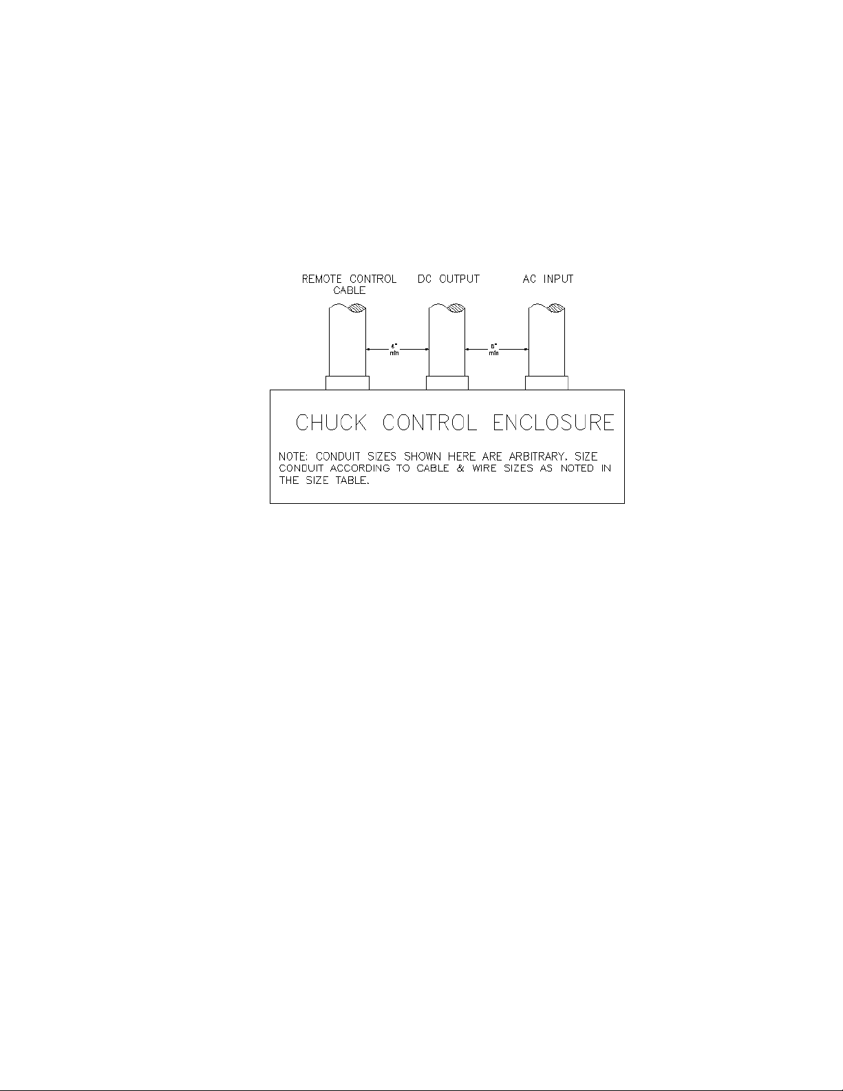
Three conduits must be routed from the main chuck control enclosure; remote control
cable, AC input and DC output. Conduit sizing should be determined in accordance with
all NFPA/NEC, state and local regulations by the qualified person installing the system.
The remote control cable must be kept a minimum of six (6) inches from high voltage
cables such as the AC input. The DC output also must be kept at least six (6) inches
from high voltage AC wiring. Refer to Figure 3-1.
Figure 3-1 Chuck Control Enclosure
MAINTAIN A SIX (6) INCH SEPARATION BETWEEN PARALLEL RUNS OF REMOTE
CONTROL CABLE AND OTHER HIGH VOLTAGE WIRING.
3.1.3 Connecting the Chuck
The DC output to the chuck must include a ground wire that is connected to the safety
ground lug on the chuck and to the chassis of the chuck control. It is recommended that
the conduit for the DC output not be routed near high voltage AC wires. Many chucks are
installed on machines with moving tables. Choose a means of wiring the chuck that
allows adequate freedom of movement over the full range of table travel.
3.1.4 Connecting the AC Input voltage
The input transformer can be tapped for nine different input voltages; 208, 220, 230, 240,
380, 416, 440, 460 and 480 VAC. Refer to the transformer wiring diagram Figure 3-2 on
the following page.
Note: that there are two (2) primary and two (2) secondary out put windings.
3.1.5 575 Volt Controllers
The transformer installed in Controllers designed to operate on 575 volts AC have a
single primary winding. Refer to the transformer wiring diagram Figure 3-2 on the
following page.
O.S. WALKER Co., Inc. SMART-D Control
3-2
SMART D MANUAL DD14511L Rev. L, March 30, 2011
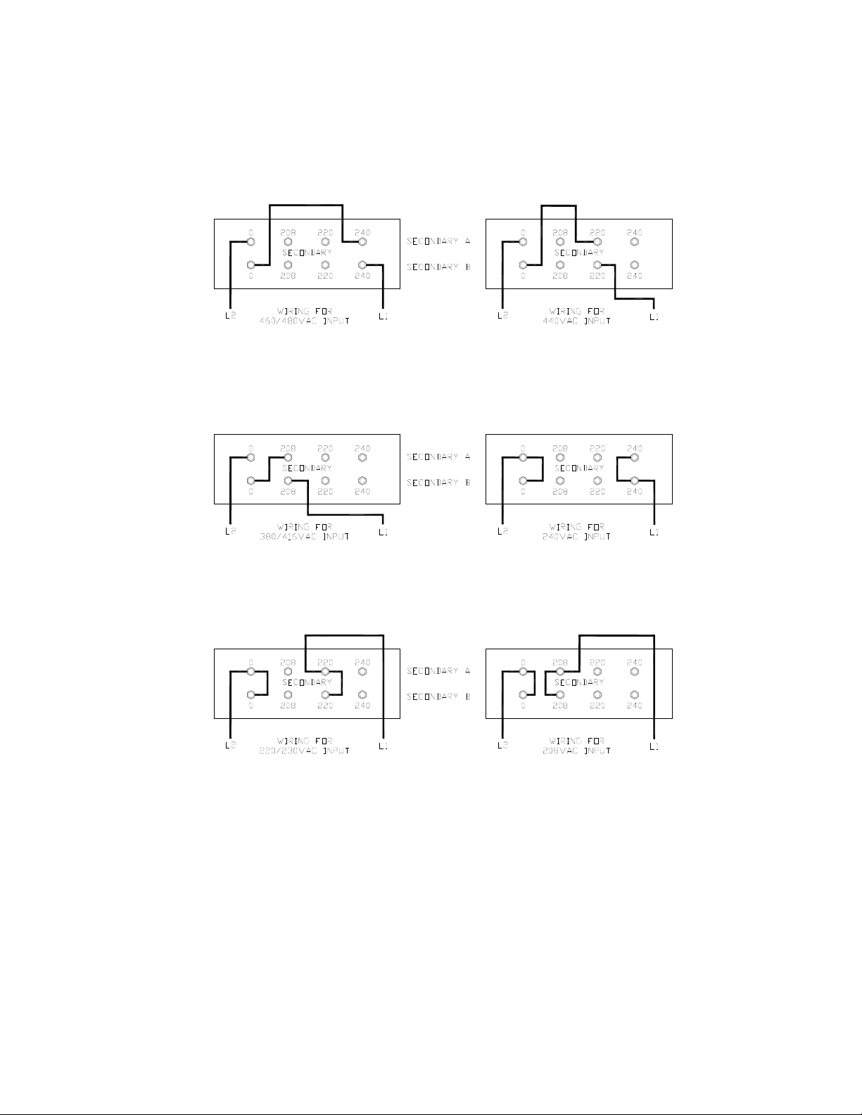
3.1.6 Transformer Wiring Diagram
O.S. WALKER Co., Inc. SMART-D Control
Figure 3-2 Transformer Wiring Diagram
3-3
SMART D MANUAL DD14511L Rev. L, March 30, 2011

3.1.7 Connecting Optional Features
SMART-D chuck controls are equipped with three optional features, Current Sensing,
Part Release and Lockout. These features enable the chuck control to work with external
equipment such as machine controls or a PLC. Refer to the "Operation" section 4 of this
manual for using of these features.
3.1.8 Current Sensing
This control is equipped with a current sensing feature that monitors the current flowing
to the chuck and indicates when this current has reached a predetermined value. The
current sense relay is a “Form C” dry contact type. The connections are at J4: Pin 6 is
common, Pin 7 is the N. O. contact, and Pin 8 is the N. C. contact. The rating of the
contacts are 10 A @ 125 VAC, 5 A @ 250 VAC, and 5 A @ 30 VDC. See Figure 5-5 for
locations.
3.1.9 Part Release
The part release relay energizes and de-energizes with the chuck. It is the same type as
the current sense relay. The connections are at J4: Pin 3 is the common, Pin 4 is the N.
O., and Pin 5 is the N. C. contact. See Figure 5-5 for locations.
3.1.10 Lockout
A Lockout feature is supplied with this control, which prevents anyone from accidentally
changing the settings while machining is in progress. There are two connections for
lockout. The first is to supply 115 VAC to J4, terminals 1 and 2. The second is to sink the
positive voltage at J5, terminal 8. This is done using a dry contact connected to terminal
8 (lockout) and terminal 13 (GND) on J5*. See Figure 5-5 for locations.
* When using lock-out, JP2 jumper must be removed.
3.1.11 Energizing the System
Inspect the conduit and wire installation. Verify that all wiring connections are correct and
secure, paying particular attention to the ground connections. Thoroughly read the
"Operating Instructions" section 4 prior to energizing any equipment.
Close all breakers and disconnects upstream of the chuck control. Close the door (on
models equipped with enclosures) and put the chuck control disconnect switch in the
"ON" position. When power is first applied, the chuck control will initialize itself in the
"Release Mode". The "Release" indicator light on the remote unit will be lit and the
current sense relay open. The system is ready for operation. No power is applied to the
chuck.
O.S. WALKER Co., Inc. SMART-D Control
3-4
SMART D MANUAL DD14511L Rev. L, March 30, 2011

3.2 Control Mounting Guidelines
1. When any control (power section) is removed from its original enclosure or shipped without an
enclosure and installed in a customer supplied enclosure, the following specifications must be
met:
a. The air surrounding the panel on which the parts are located should not exceed 120°
Fahrenheit.
b. The air temperature must be measured:
1) With the control in the Full holding position;
2) After the control has been in operation for 30 minutes; and
3) With the chuck holding the largest load to be used.
2. When any control (power section) is to be placed in a secondary enclosure while still in its
original enclosure, the following specifications must be met:
a. With the control (power section) mounted in its original enclosure and then mounted in a
secondary enclosure, the air surrounding the original enclosure should not exceed 104°
Fahrenheit.
b. The air temperature must be measured:
1) With the control in the Full holding position;
2) After the control has been in operation for 30 minutes; and
3) With the chuck holding the largest load to be used.
O.S. WALKER Co., Inc. SMART-D Control
3-5
SMART D MANUAL DD14511L Rev. L, March 30, 2011

4 OPERATING INSTRUCTIONS
The O. S. Walker Microprocessor Chuck Control, model SMART-D, uses a remote unit that can
select the following functions: Full Holding; Variable Holding; Residual Holding; and Release. This
control comes equipped with an adjustment for the number of pulses per Release cycle. It also has
additional options, which are a Part Released feature, a Current Sense feature, and a Lockout
feature.
4.1 Important Facts about Magnetic Holding
Workpiece characteristics must be considered in order to determine the magnetic holding
attraction that a magnetic chuck can provide.
This is true for all magnetic chucks because they all operate using the same fundamental
laws of physics. Magnetic power is often pictured as lines of magnetic force flowing from north
to south pole. Anything that limits the flow of these magnetic lines of force obviously reduces
the magnets holding capacity. There are many important factors that limit the flow of these
lines of force.
4.1.1 Surface Conditions
Magnetic lines of force do not flow easily through air. They need iron in order to flow
freely; therefore, anything that creates a space or an air gap between the magnet and the
workpiece limits the flow of magnetic lines of force and, thus, reduces the holding
capacity of a magnetic chuck.
• Magnetic Chuck Surface Condition -- The holding surface of a magnetic chuck must
be clean, smooth, flat, and free of nicks or burrs in order to minimize the air gap
between the chuck holding surface and the Workpiece. All Walker chucks are
designed with soft, low carbon steel magnetic poles in the top plate in order to
maximize the holding capacity; therefore, special care must be taken to protect these
areas.
• Workpiece Surface Condition -- The holding capacity of the chuck will be reduced if
certain surface conditions exist. A rough surface finish on the workpiece creates an air
gap as also foreign materials like dirt, paint, rust, paper, and rags.
O.S. WALKER Co., Inc. SMART-D Control
4-1
SMART D MANUAL DD14511L Rev. L, March 30, 2011

4.1.2 Workpiece Thickness
The greater the number of lines of magnetic force flowing from a magnet into the
workpiece the greater the effectiveness of the magnetic chuck. The thicker the workpiece,
the more lines of magnetic force are able to flow. After a certain thickness of the
workpiece, no additional lines of force will flow because the magnet has reached its full
capacity.
• Thin workpieces mean less iron available, and thus fewer lines of magnetic force flow
from the magnet into the workpiece. Therefore, the chuck holding capacity is reduced.
• Typically, the minimum thickness of a workpiece required to reach full holding capacity
is the same as the thickness of the chuck major magnetic steel poles.
4.1.3 Portion of the Chuck Surface In Contact With the Workpiece
The full surface of the chuck top plate must be covered by the workpiece to achieve the
maximum holding capacity. The surface of the workpiece must contact equal areas of the
chuck opposite polarity major magnetic poles to obtain maximum holding force.
4.1.4 Workpiece Material
Low carbon steel such as SAE 1020 steel, are nearly as good conductors of magnetic
lines of force as pure iron. However, many other alloys contain non-magnetic materials
which reduce the ability of magnetic lines of force to flow. An alloy such as SAE 300
series stainless steel is almost as poor a conductor of magnetic lines of force as air.
Type 416 stainless steel is considered magnetic, but it contains enough chromium so that
a magnet can develop only about one half as much magnetic force as it can on an SAE
1020 steel workpiece. Also, because of the carbon content, the force developed on typical
cast iron is less than one half that developed on SAE 1020 steel. (Chilled cast iron further
reduces the force to less than one quarter.)
Additional concerns regarding Magnetic Holding should be forwarded to O. S. Walker,
Inc.
O.S. WALKER Co., Inc. SMART-D Control
4-2
SMART D MANUAL DD14511L Rev. L, March 30, 2011

4.2 Full Holding
(Green Push-Button)
In the Full holding position, full output voltage is supplied from the control to the chuck as
soon as this function is selected. The indicator light for the Full holding position is illuminated
when this function is selected.
NOTE: Full holding has equivalent holding force to 100% on the Variable holding
control knob.
4.3 Variable Holding
(White Push-Button)
When the operator presses the Variable holding button, the output voltage of the control can
be adjusted from zero to full with the Variable control knob.
A varying amount of Residual hold can be achieved by turning the Variable control knob to
zero from its previous holding position without pressing the Residual button.
4.4 Residual Holding
The output of the control is reduced to zero when this function is selected. The control turns
the chuck fully ON for a short period of time, thus leaving a recognizable residual holding
power in the chuck; this is called True Residual. During this brief pulse, the indicator light, will
be ON until another function is selected.
4.5 Release
Selecting the Release function initiates an automatic release cycle. During the release cycle,
the output voltage produced by the control is reduced from full to zero in a predetermined
number of equal pulses (see Figure 4-1). The polarity of these pulses alternately reverses
from negative to positive as the magnitude of the voltage decreases. The SMART-D can
generate a maximum of sixteen pulses per release cycle, but is set at the factory for eight.
The Release indicator light will flash ON and OFF to show that release is taking place, and
will remain ON when the cycle is complete.
The duration of each pulse is automatically controlled. The time between pulses is
automatically adjusted by the control for the optimum Release cycle time.
The SMART-D has an external and internal adjustment for the number of pulses per Release
cycle. This adjustment allows the operator to select the number of pulses it takes to get the
fastest, most complete release of a part.
O.S. WALKER Co., Inc. SMART-D Control
4-3
SMART D MANUAL DD14511L Rev. L, March 30, 2011

The external adjustment for the number of demagnetization pulses per Release cycle is done
using the full, residual, release pushbuttons, and the Variable potentiometer. To adjust the
number of release pulses, the control must be "at the end of the release cycle". The
procedure for externally adjusting the number of Release pulses is as follows:
1. Hold the Release button down and PRESS the Full button. With some control revisions
you may have to press the Full button again after you have let go of the Release
button.
2. Using the table below, you can adjust the number of release pulses by turning the
Variable adjustment knob.
Number of Release Pulses 1 23456789101112 13 14 1516
Variable Lamp/LED XXXXX X X X
Residual Lamp/LED XXXX X X X X
Full Lamp/LED X X X X X X X X
Release Lamp/LED X X X X X X X X
X indicates lamp/led is on.
3. Once the number of desired Release pulses has been set, PRESS the Residu al
button.
4. The control is now ready for operation.
The internal adjustment for the number of demagnetization pulses per Release cycle is
located on the main pc board.
The procedure for internally adjusting the number of release pulses is as follows:
1. Turn off power to the control and open the enclosure.
2. Remove JP1 Jumper (Pot Disable) located on the main pc board.
NOTE: THE EXTERNAL ADJUSTMENT WILL NOT OPERATE WITHOUT JP1 INSTALLED.
3. Turn P1, with a small straight-bladed insu lated screwdriver, clockwise to increase the
number of pulses or counter-clockwise to decrease the number of pulses.
4. Close the enclosur e and restore power.
O.S. WALKER Co., Inc. SMART-D Control
4-4
SMART D MANUAL DD14511L Rev. L, March 30, 2011

4.6 Control Protection
If the control is switched into sudden high power operation with too large a load, the AC fuse
may blow before the electronic protective circuits can function.
If the chuck control is overloaded by a short circuit or a chuck too large for this control's rating,
the control will sense this condition and will attempt to protect itself by flashing all the system
indicator lights, and the control will not respond to any function selection. This will continue
until AC power is removed from the control and the problem is corrected.
The logic section of the Main PC Board is protected by a .125A fuse in location F1. This fuse
will blow if a problem occurs in the logic section.
If AC power is interrupted while the control is running, the control returns to the mode of
operation selected just prior to loss of power. This allows easy resumption of machining after
an AC line dropout.
4.7 Release Cycle Steps
The Release Cycle removes residual magnetism in the chuck and workpiece by sending
decreasing, alternating pulses of DC voltage through the chuck coils. The amount of
demagnetization (DEMAG) depends upon the number of pulses, the length of time that the
pulses are applied (T = Pulse width) and the time between pulses (t = Off Time). The first
pulse is always negative. The pulse voltages are determined automatically by the chuck
control software. The number of demagnetization pulses are adjustable from one to sixteen
(1-16). The pulse width and off time are automatically adjusted by the on-board
microprocessor. See Figure 4-1.
O.S. WALKER Co., Inc. SMART-D Control
4-5
SMART D MANUAL DD14511L Rev. L, March 30, 2011

Figure 4-1 Release Cycle Voltage VS. Release Cycle Time
O.S. WALKER Co., Inc. SMART-D Control
4-6
SMART D MANUAL DD14511L Rev. L, March 30, 2011

4.8 Grounding & Shielding
The optional chuck control outputs for current sense and part released are isolated from the
control circuit ground. All other chuck control electrical inputs and outputs, if connected to
electronic equipment, must be isolated from the control's internal circuit ground, which is
connected to the AC safety ground (the green or green/yellow wire in the AC line cord). The
base of the chuck is to be grounded to this point, as well as, through the ground wire of the
DC chuck cable. All electrical chassis must be safety grounded.
The chuck control's DC power output leads MUST BE SEPARATELY ROUTED from other
115V level power leads in the machine. They must not be routed in the same wire bundle with
400V or other high voltage leads. If the control has LOW VOLTAGE signal leads wire through
the machine, these MUST BE SEPARATELY ROUTED in their own SHIELDED WIREWAY
and the shield grounded to the machine chassis. Low voltage signals must not be routed with
high voltage or high power cables through any part of the machine, or electromagnetic
interference may result.
4.8.1 Current Sensing
This control is equipped with a current sensing feature that monitors the current flowing
to the chuck and indicates when this current has reached a predetermined value. The
predetermined value is set by adjusting the variable potentiometer to the desired point
and then pressing the residual pushbutton while holding down the variable pushbutton.
When the preset value is reached, the Variable indicator light stays on and the current
sense relay closes. If the current flowing to the chuck goes below the preset value, the
variable light will flash. See section 3.1.8 for more information.
4.8.2 Part Release
When the control enters the Full and Variable modes Part Release relay energizes.
When the control comes to the end of a release cycle the Part Release relay deenergizes. See section 3.1.9 for more information.
4.8.3 Lockout
A Lockout feature is supplied with this control which prevents anyone from accidentally
changing the settings while machining is in progress. When the lockout signal is low
(0V), the feature is disabled and when the signal is high (+5V), the feature is enabled.
The feature can be operated in two different manners. See section 3.1.10 for more
information.
4.9 Control Output Voltage
The DC voltage for the magnet is connected across terminals 1 and 2 on TB1. This voltage
may be measured across these terminals and can vary from 0-115VDC and 0-230VDC
depending on the model control and its settings.
O.S. WALKER Co., Inc. SMART-D Control
4-7
SMART D MANUAL DD14511L Rev. L, March 30, 2011

5 MAINTENANCE & TROUBLESHOOTING
5.1 Inspection & Maintenance
• Check the physical condition of the power cords, indicating lamps, switches and the
control enclosure. If any indications of damage are observed, contact your supervisor.
• Check the integrity of the enclosure by inspecting for dust, debris and fluid.
• Keep the outside of the enclosure free of dust and debris.
5.2 Having a Problem with your Chuck Control?
Problem Probable Cause Solution
1. All the remote
unit lights are
flashing
2. None of the
control unit lights
are illuminated
and it does not
respond to any
operating mode
The load is drawing
excessive current and
the control unit has
protected itself by
disabling all operating
modes.
Input voltage is too low
or wired incorrectly.
Remote unit is not
properly wired.
BEFORE PROCEEDING, DE-ENERGIZE THE
CONTROL UNIT.
a) Verify the chuck power rating does not
exceed the control's power rating.
b) Disconnect the chuck from the control unit
and verify that the chuck's coil windings are
not shorted.
c) Repair/replace where required.
d) With the load disconnected, re-energize
equipment and cycle through all operating
modes, verifying proper operation.
e) Repeat step d. with the load reconnected.
f) Having successfully completed the above
and unit does not function properly, contact
O.S. Walker, Inc.
a) Verify the input voltage to the control unit
(see Installation section 3).
BEFORE PROCEEDING, DE-ENERGIZE THE
CONTROL UNIT.
b) Verify that all fuses are good (see Standard
Interface Diagram section Error! Reference
source not found. for location). Use only
exact replacement fuses to avoid damaging
unit or causing a safety hazard.
c) Verify the wiring between the control unit
and the remote unit (see Standard Interface
Diagram section Error! Reference source
not found.).
d) Having successfully completed the above
and the unit does not function properly,
contact O.S. Walker, Inc.
O.S. WALKER Co., Inc. SMART-D Control
5-1
SMART D MANUAL DD14511L Rev. L, March 30, 2011

3. The fuse in the
control unit blows
when any of the
control modes
are selected.
Excessive current draw
is causing fuse to blow
before electronic
protective circuits have
time to react.
BEFORE PROCEEDING, DE-ENERGIZE THE
CONTROL UNIT.
a) Visually inspect chuck cable and
connections for pinches or other damage.
b) Check chuck cable and connections for
shorts with ohmmeter.
c) Replace any questionable equipment.
d) Use only exact replacement fuses to avoid
damaging the unit or causing a safety
hazard.
e) Re-energize equipment and cycle through all
operating modes, verifying proper operation,
with the load disconnected.
f) Repeat step e. with the load connected.
g) Having successfully completed the above
and the unit does not function properly,
contact O.S. Walker, Inc.
O.S. WALKER Co., Inc. SMART-D Control
5-2
SMART D MANUAL DD14511L Rev. L, March 30, 2011

5.3 Chuck Control Connections
Table 5-1 Terminal TB1
1 (+) Chuck DC
2 (-) Chuck DC
Table 5-2 Connector - J4
1,2 Lockout Supply Relay Contacts
3,4,5 Part Released Signal Relay Contacts
6,7,8 Current Sense Relay Contacts
Table 5-3 Connector - J5
1 50K Ohm Variable Potentiometer
2 GND
3 Release Lamp
4 Variable Lamp
5 Full Lamp
6 Residual Lamp
7 LED Common
8 Lockout Option
9 Variable Pushbutton
10 Full Pushbutton
11 Residual Pushbutton
12 Release Pushbutton
13 GND (Pushbutton Common)
14 +5V
15 # of Release Pulses
16 Lamp Common
Adjustments
Number of Release Pulses (1-16) - Set to 8 pulses at factory (See Release section 4.5 page
4-3)
O.S. WALKER Co., Inc. SMART-D Control
5-3
SMART D MANUAL DD14511L Rev. L, March 30, 2011

5.4 Remote Interface
5.4.1 Connections:
Table 5-4 Remote TB = TBR (located in remote enclosure); J5 (located on main PC board)
TBR:1 to J5:1
TBR:2 to J5:2
TBR:3 to J5:3
TBR:4 to J5:4
TBR:5 to J5:5
TBR:6 to J5:6
TBR:7,14 to J5:7
TBR:8 NC
TBR:9 to J5:9
TBR:10 to J5:10
TBR:11 to J5:11
TBR:12 to J5:12
TBR:13 to J5:13
5.5 Interface
J4:1 Lockout Signal
J4:2 Lockout Common
J4:3 Part Release Common
J4:4 Part Release NO
J4:5 Part Release NC
J4:6 Current Sense Common
J4:7 Current Sense NO
J4:8 Current Sense NC
O.S. WALKER Co., Inc. SMART-D Control
5-4
SMART D MANUAL DD14511L Rev. L, March 30, 2011

5.6 Smart 75/100D Panel Layout
O.S. WALKER Co., Inc. SMART-D Control
Figure 5-1 Smart 75/100D Panel
5-5
SMART D MANUAL DD14511L Rev. L, March 30, 2011

5.7 Smart 20/30/50D Panel Layout
O.S. WALKER Co., Inc. SMART-D Control
Figure 5-2 Smart 20/30/50D Panel
5-6
SMART D MANUAL DD14511L Rev. L, March 30, 2011

5.8 Smart 7/10/15D Panel Layout
O.S. WALKER Co., Inc. SMART-D Control
Figure 5-3 Smart 7/10/15D Panel
5-7
SMART D MANUAL DD14511L Rev. L, March 30, 2011

5.9 Smart 3/5D Panel Layout
O.S. WALKER Co., Inc. SMART-D Control
Figure 5-4 Smart 3/5D Panel
5-8
SMART D MANUAL DD14511L Rev. L, March 30, 2011

5.10 Main PC B oard
O.S. WALKER Co., Inc. SMART-D Control
Figure 5-5 Main PC Board
5-9
SMART D MANUAL DD14511L Rev. L, March 30, 2011

5.11 Smart 75/100D Wiring
Reference documentation included for schematics.
O.S. WALKER Co., Inc. SMART-D Control
Figure 5-6 Smart 75/100D Wiring
5-10
SMART D MANUAL DD14511L Rev. L, March 30, 2011

5.12 Smart 20/30/50D Wiring
Reference documentation included for schematics.
O.S. WALKER Co., Inc. SMART-D Control
Figure 5-7 Smart 20/30/50D Wiring
5-11
SMART D MANUAL DD14511L Rev. L, March 30, 2011

5.13 Smart 7/10/15D 115V Wiring
Reference documentation included for schematics.
O.S. WALKER Co., Inc. SMART-D Control
Figure 5-8 Smart 7/10/15D 115V Wiring
5-12
SMART D MANUAL DD14511L Rev. L, March 30, 2011

5.14 Smart 7/10/15D 200V Wiring
Reference documentation included for schematics.
O.S. WALKER Co., Inc. SMART-D Control
Figure 5-9 Smart 7/10/15D 230V Wiring
5-13
SMART D MANUAL DD14511L Rev. L, March 30, 2011

5.15 Smart 3/5D 115VDC Wiring
Reference documentation included for schematics.
O.S. WALKER Co., Inc. SMART-D Control
Figure 5-10 Smart 3/5D 115VDC Wiring
5-14
SMART D MANUAL DD14511L Rev. L, March 30, 2011

5.1 Smart 3/5D 230VDC Wiring
Reference documentation included for schematics.
O.S. WALKER Co., Inc. SMART-D Control
Figure 5-11 Smart 3/5D 230VDC Wiring
5-15
SMART D MANUAL DD14511L Rev. L, March 30, 2011

5.2 Enclosure Dimensions for SMART-D Controls
SMART
MODEL #
WATTAGE
CAPACITY
STANDARD
OUTPUT
VOLTAGE
3D 300 115VDC
5D 500 115VDC
7D 750 115/230VDC
10D 1000 115/230VDC
15D 1500 115/230VDC
20D 2000 230VDC
30D 3000 230VDC
50D 5000 230VDC
75D 7500 230VDC
100D 10000 230VDC
ENCLOSURE
DIMENSIONS
WIDTH (W) 12” 20” 24” 24” WIDTH (W) 9” 17” 21” 21”
HEIGHT (H) 20” 30” 30” 30” HEIGHT (H) 17” 27” 27” 27”
DEPTH (D) 8” 10” 12” 12” DEPTH (D) N/A N/A N/A N/A
MTG. HOLE
DIAMETER
MTG. HOLES
HORIZONTAL
SPACING (V)
MTG. HOLES
VERTICAL
SPACING (X)
MSD3
MSD5
.44” .44” .44” .44” MTG. HOLE
9.50” 14” 18” 18” MTG. HOLE
21.25” 31.25” 31.25” 31.25” MTG. HOLES
MSD7
MSD10
MSD15
MSD20
MSD30
MSD50
MSD75
MSD100
PANEL
DIMENSIONS
DIAMETER
HORIZONTAL
SPACING (V)
VERTICAL
SPACING (X)
MSD3
MSD5
.41” .41” .41” .41”
7.25” 15.25” 19.25” 19.25”
15.25” 25.25” 25.25” 25.25”
MSD7
MSD10
MSD15
MSD20
MSD30
MSD50
MSD75
MSD100
O.S. WALKER Co., Inc. SMART-D Control
5-16
SMART D MANUAL DD14511L Rev. L, March 30, 2011

5.3 Remote Enclosure Dimensions
O.S. WALKER Co., Inc. SMART-D Control
Figure 5-12 Remote Enclosure BB-8783
5-17
SMART D MANUAL DD14511L Rev. L, March 30, 2011

5.4 Remote Wiring Connections
O.S. WALKER Co., Inc. SMART-D Control
Figure 5-13 Remote Wiring Connections
5-18
SMART D MANUAL DD14511L Rev. L, March 30, 2011

5.5 Replacement Parts List
Table 5-5 Replacement Parts
PART NUMBER DESCRIPTION
SMART 3/5D SMART 7-15D SMART 20-50D SMART 75D SMART 100D
Main PC Board 39-DD14329 39-DD14520 39-DD14520A
Remote Control 56-BB8783
Transformer T1
(208/480 Volt)
SCR Module N/A 23-4048 N/A N/A N/A
Relay K1 N/A 13-0220 13-0344 N/A N/A
Contactor K1 N/A N/A N/A 13-1300 13-0469
Fuse F1,F2 (500V)
Fuse F1,F2 (600V)
Fuse F3 N/A N/A N/A N/A N/A
Fuse F1 (on pcb) 18-1340 CSA
Fuse F2 (on pcb) 18-1341 CSA
Diode D1 N/A N/A 23-0212 N/A N/A
SCR1,2 N/A N/A 23-4051 N/A N/A
Diode Module D1-D4 N/A N/A N/A 23-0221 23-0221
Solid State Relay N/A N/A N/A 13-0459 23-0459
12-0094 12-2001 12-0302 12-0504 12-0355
18-1011 18-1074 18-1234 18-1327 18-1336
18-1309
18-1311
18-1340
18-1309
18-1341
18-1311
18-1340
18-1309
18-1341
18-1311
18-1340
18-1309
18-1341
18-1311
18-1340
18-1309
18-1341
18-1311
*Walker replacement parts may be installed by a **Designated Person.
** Designated Person - A person selected or assigned by the employer as being competent
to replace specific replacement parts listed in this manual and is able to verify the proper
functioning of the specific replacement parts and the entire product after the completion of the
installation.
O.S. WALKER Co., Inc. SMART-D Control
5-19
SMART D MANUAL DD14511L Rev. L, March 30, 2011

6 RETURN AND REPAIR INSTRUCTIONS
For warranty and non-warranty repairs on any part of your chuck system, contact O.S. Walker
Company TOLL FREE at 1-800-W-MAGNET. A return authorization number will be issued along
with any applicable packaging and shipping instructions. After receipt of the components to be
repaired, O.S. Walker Company will perform an inspection and provide an estimate of the repairs
costs at no charge to the customer. Authorization from the customer must be obtained by O.S.
WALKER Company before repairs are made. Transportation charges, both to and from the factory,
are the sole responsibility of the customer.
O.S. WALKER Co., Inc. SMART-D Control
6-1
SMART D MANUAL DD14511L Rev. L, March 30, 2011

FOR FAST RESPONSE, CALL 1-800-W-MAGNET
O.S. WALKER
Rockdale Street, Worcester, MA 01606
(508)-853-3232 FAX (508)-852-8649
3508 Glenridge Drive, Chino Hills, CA 91709
(909)-597-4785 FAX (909)-597-0581
901 Arvin Avenue, Stoney Creek, Ontario, L8E5N9 Canada
(905)-643-3338
In Canada: 1-800-267-4678 FAX (905)-643-6111
www.walkermagnet.com
e-mail: info@walkermagnet.com
O.S. WALKER Co., Inc. SMART-D Control
SMART D MANUAL DD14511L Rev. L, March 30, 2011
 Loading...