

WALKER FILTRATION PROSFD, PROSFD PD0046, PROSFD PD0056, PROSFD PD0075, PROSFD PD0110 Series Manual
...Page 1
PROSFD
PROSFD
PROSFD
Page 2

The product to which this manual refers must not be supplied, installed,
used, operated or serviced until the contents of the manual has been
fully read and understood by all relevant personnel.
Please complete the following information at the time of installation
found on the rating label on the upper right hand side of dryer
Model Number
Serial Number
Regulated Inlet Pressure
Filtration present with Dryer
Inlet Flow of Dryer
Supply Voltage
Page 3

Contents
1 Safety 5
Safety Guidelines 5
Symbols 6
2 General Description 7
Function of the Dryer 7
Controller Options 7
Package Contents 8
Primary Components 9 - 10
3 Technical Data 11
Environmental Conditions 11
Dimensional Specications 12
Sizing 13
4 Mechanical Installation 14
Orientation 16
Conguration of the inlet /outlet ports 17
Connecting the pre-lter to the dryer 18
Connecting the optional pre-lter drain valve 18
Installing the hygrometer (DMC models only) 19
Conguring the purge orice 20
5 Electrical Installation 22
PRODRY Controller power supply options 22
PRODRY Recommended power cable specications 22
LED Controller specications 23
DMC Controller specications 24
How to wire a DIN connector 25
Alarm connection details 26
Page 4

6 Operation 27
Background / Function of the Dryer 27
Detailed operational description - LED Controller 27
Detailed operational description - DMC Controller 27
Start-up procedure 28
Shut-down procedure 28
Operational schematics 29
7 Energy Management 35
Overview 35
Developing a purge control strategy 35
Using a manual switch for purge control 35
Using a standard pressure switch for purge control 36
Using an electronic pressure switch for purge control 37
Using a hygrometer and process controller for purge control 38
Making connections between a switching device and dryer EM contact 39
8 Maintenance 40
9 Spares Information 41
Service kits 41 - 43
Accessory kits 44 - 45
10 Component Parts 46
11 Troubleshooting 50
12 Warranty 56
13 Declaration of Conformity 57
Page 5

Section 1: Safety
Safety
The following safety guidelines must be
strictly observed.
• Leave this manual at the place of installation of
the product.
• It is essential that only Walker Filtration or it’s appointed
agents carry out maintenance and servicing work.
Users, maintenance and servicing personnel must be familiar
with:
• Accident prevention regulations.
• Safety information (general and specic to the unit).
• Safety devices of the unit.
• Measures to be taken in case of an emergency.
• Allow only suitably trained persons to be involved with
installation, start-up, operation, servicing and maintenance
of the product.
• It is the responsibility of the installer to ensure that the
pipe work to and from the dryer is suitable, in accordance
with applicable legislation and subject to inspection and
testing prior to being put into service. All piping must be
adequately supported.
• Before carrying out any maintenance or servicing work the
unit must be taken out of operation. Users and others will
be exposed to risk if work is carried out whilst the unit is
running. This means electrical disconnection plus isolation
from the compressed air supply and full depressurisation.
• Only trained and competent persons familiar with the
electrical requirements of the unit as laid out in this
manual and electrical safety rules and regulations should
be allowed to carry out work on the electrical components
and power supply to the unit.
• When carrying out any work on the unit, use only
correctly sized appropriate tools in good condition.
• Only use original spare parts and accessories from the
manufacturer. There is no guarantee that non-original
parts have been designed and manufactured to meet
the safety and operational requirements of the unit.
Walker Filtration assume no liability for any equipment
malfunction resulting from the use of non-approved parts.
• If carrying out installation work above head height, use
suitable and safe working platforms or other means of
working access.
• Do not make any constructional changes to the product.
Any changes or modications may only be carried out by
the manufacturer, Walker Filtration.
• Any faults or defects that could affect safety must be put
right fully before using the unit.
• Used items and materials must be disposed of in the
correct manner, complying with local laws and regulations,
in particular the desiccant cartridge.
5
Page 6
Section 1: Safety
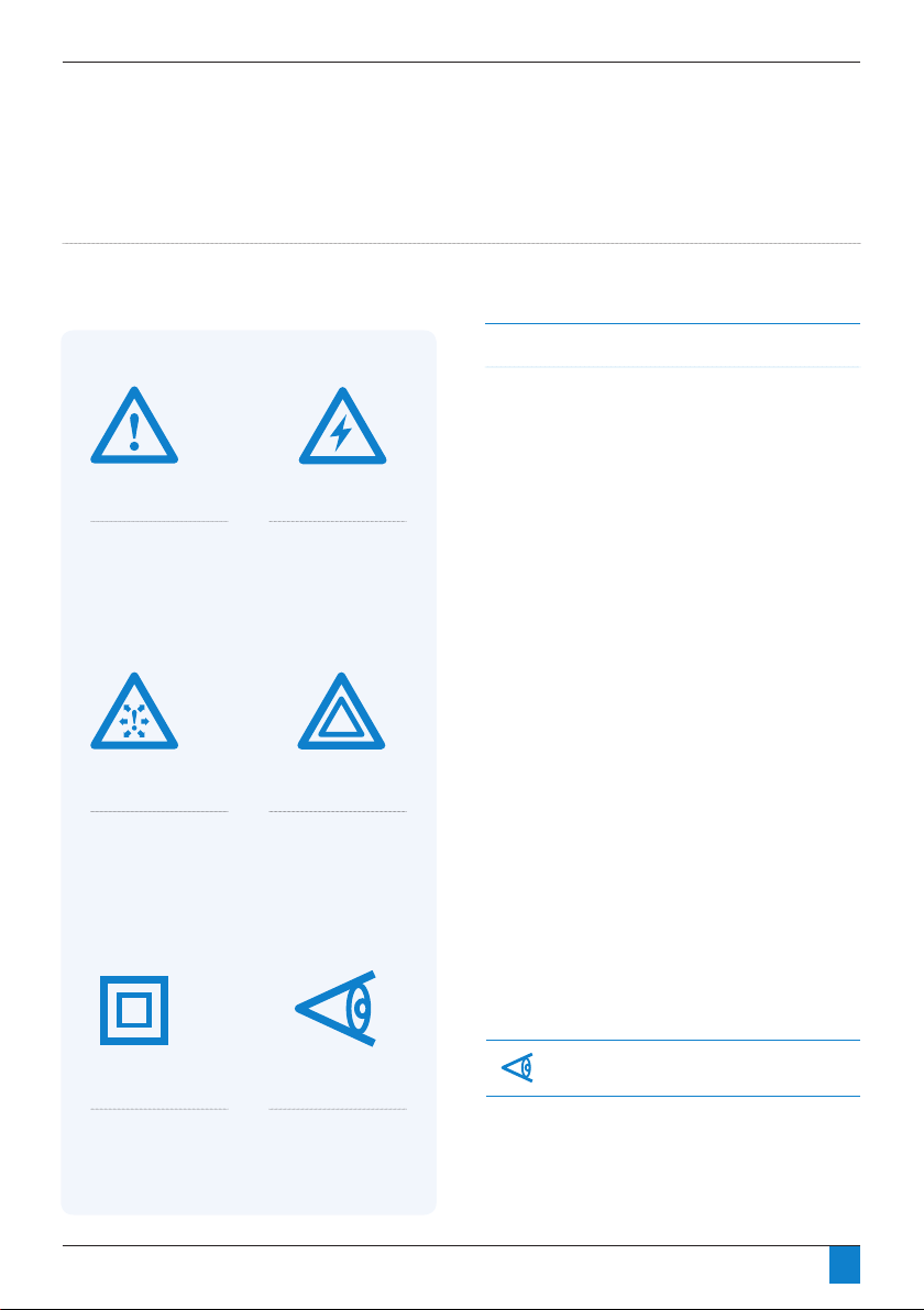
Figure 1.1: Definition of symbols
Risk of Danger
Risk of High Pressure
Risk of Electric Shock
Warning
Manual Handling
As with all areas of the workplace, Health and Safety is of
great importance and must be given due care and attention.
While working with this equipment, manual handling
regulations must be considered and adhered to.
Full advice, support and guidance should be detailed in your
Health and Safety Policy and Manual Handling guide, please
take the time to familiarise yourself with these documents.
The Manual Handling Operations Regulations apply to a wide
range of manual handling activities, including lifting, lowering,
pushing, pulling or carrying.
We ask every person handling this product to take the
responsibility for their own Health and Safety and the Health
and Safety of others around them. If you feel there is a
signicant risk, you must take steps to either remove the risk
altogether, or reduce the risk prior to carry out the activity. If
you need further support or guidance with this, please consult
your line manager or the HR Department.
There are safe systems of work and correct procedures in
relation to manual handling, please consult these documents
available within the workplace.
We ask everyone handling this product to:
• Follow appropriate systems of work laid down
for their safety.
• Make proper use of any equipment provided for
their safety.
• Inform the company if they identify hazardous
handling activities.
• Take care to ensure that their activities do not put
others at risk.
If in doubt, please seek further advice and ensure you always
follow the correct procedures and guidance.
For more information please see our Health and
Safety manual attached.
Equipment Protected by
Double Insulation
Important Note
A 3 amp fuse should be tted as per the wiring diagram.
6
Page 7

Section 2: General Description
Controller Options
RESET
Controller Options
RESET
Dewpoint Hold (-40)
Dryer Dewpoint -43 PDP
Hours Run 1234
Service History # 0
General Description
This manual is valid for the following dryer models
PD0046
PD0056
PD0075
PD0090
PD0110
PD0150
PD0180
PD0220
PD0300
PD0360
Function of the Dryer
PRODRY is designed to provide a smooth, controlled and
uninterrupted delivery of dry compressed air. Wet air passes
through a pre-lter and travels down to the bottom valve
assembly. The air is then fed through the bottom of the
desiccant bed and moves through the high performance
desiccant until it becomes dry. On exit from the desiccant
cartridge, the air is passed through the outlet valve assembly.
During this process, the dryer control system cycles the process
air between the two desiccant towers. While one tower is on
stream removing water vapour, the other is being carefully
depressurised in preparation for regeneration. The desiccant
bed is regenerated by expanding a small amount of dry
process air, or purge air, through the saturated desiccant.
Purge air passes to atmosphere through the silencer, which
is tted to an exhaust valve. The tower is then repressurised,
with the control system assuring each tower is at full
operational pressure prior to changeover.
This ensures a reliable and efcient operation. The air stream is
switched and the cycle repeats on a continuous basis.
Figure 2.1: LED Controller
Features:
• Supplied as standard controller
• Microcontroller based design
• Available in 115V or 230VAC
• Energy Management Feature (EM)
• Alarm Outputs
Figure 2.2: DMC Controller
Features:
• (Optional) full feature controller
• PLC based design
• 24VDC only
• Includes Hygrometer
• Energy Management Feature (EM)
• Alarm Outputs
• Selectable output dewpoint levels (-20°C, -40°C, -74°C)
• Engages Dewpoint Hold during periods of low demand
• resulting in energy savings up to 81%.
7
Page 8

Controller Options
Controller Options
Section 2: General Description
1
2
3
4
1
6
2
3
4
5
1
6
2
3
4
5
Package Contents
The dryer is delivered in protective packaging. Take care when transporting, loading and unloading the unit.
The package contains the following items (refer to gure 2.3):
1. Dryer unit
2. Instruction manual (including certicate of conformity)
3. Power connector
Figure 2.3: Package contents (All dryer models)
4. Purge Kit
Figure 2.4: Optional Items for DMC Dryer
Hygrometer Sample Block
(Installed into top valve block)
Hygrometer
Instruction manual
(including certicate of conformity)
Note: All dryers come equipped with
eyebolts to facilitate removing the dryer
from it’s crate. Simplex dryers include one
eyebolt and duplex models include two.
Note: All dryers include spare orice
components to allow the dryer to be
modied from the factory 7 barg (100 psig)
pressure setting to any pressure within the
specied operating range. The internal
purge valves within models PD046 & PD056
can be modied to suit all pressure settings
whilst models PD0075 to PD0360 require
additional components (which are supplied
with the dryer).
Figure 2.5: Optional Items for DMC Dryer
Pre-lter drain valve
7
8
Page 9
Section 2: General Description
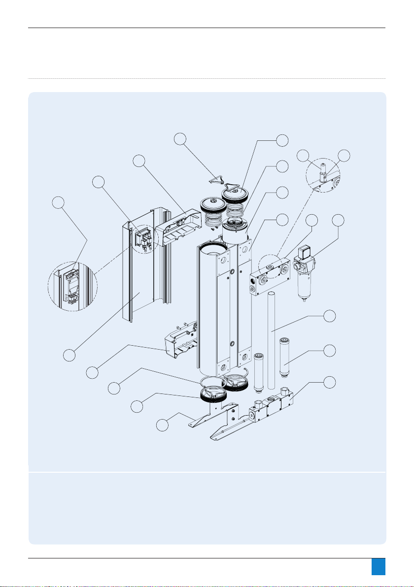
Figure 2.6: Primary Components (Simplex Models PD0046 - PD0180)
DMC Models2b
1
2a LED Models
17
16
4
3
5
19
18
6
DMC Models
7
8
9
10
11
12
13
15
14
1. Front panel
2a. LED controller
2b. DMC controller
3. Top trim cover
4. Extrusion cover
5. Top extrusion tower plug
6. Tower spring
7. Desiccant cartridge
8. Extrusion tower
9. Top manifold assembly
10. Pre-filter (Optional)
11. Downpipe
12. Exhaust silencer
13. Bottom manifold assembly
14. Dryer stand
15. Bottom extrusion tower plug
16. Tower circlip
17. Bottom trim cover
18. Hygrometer sample block*
19. Hygrometer*
* DMC models only
9
Page 10
Section 2: General Description
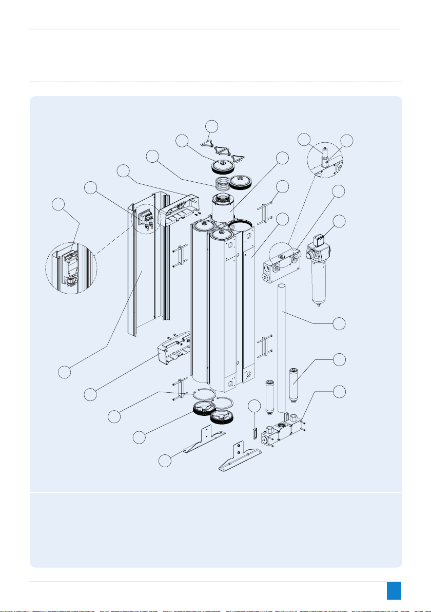
Figure 2.7: Primary Components (Duplex Models PD0220 - PD0360)
Se ctio n 2: General Description
Figure 2.7: Primary Components (Duplex Models PD0220 - PD0360)
6
2
DMC Models2b
3
4
5
21
7
8
9
20
DMC Models
10
11
12
13
1
19
14
15
18
17
16
1. Front panel
2a. LED controller
2b. DMC controller
3. Top trim cover
4. Extrusion cover
5. Top extrusion tower plug
6. Tower spring
7. Desiccant cartridge
8. Extrusion link
9. Extrusion tower
10. Top manifold assembly
11. Pre-filter (Optional)
12. Downpipe
13. Exhaust silencer
14. Bottom manifold assembly
15. Bottom manifold support clip
16. Dryer stand
17. Bottom extrusion tower plug
18. Tower circlip
19. Bottom trim cover
20. Hygrometer sample block*
21. Hygrometer*
* DMC models only
10
Page 11

Section 3: Technical Data
Technical Data
Environmental Conditions
All dryers are designed to be safe under the following conditions:
• Indoor use
• Altitude up to 2,000m
• Ambient temperature 5°C (41°F) to 50°C (122°F)
• Mains supply voltage uctuations not to exceed +/- 10% of nominal
For operation extended from the above conditions, please contact Walker Filtration.
Excessive vibrations from external sources may cause
failure of this product.
Rated Conditions
Measurement
Inlet pressure 7 barg 101.5 psig
Inlet temperature 35°C 95°F
Relative humidity of air at inlet 95%
Pressure dewpoint, standard version -40°C -40°F
Performance
Specified Limitation for Operation
Measurement
Maximum inlet air pressure 13 barg 188.5 psig
Minimum inlet air pressure 4 barg 58 psig
Maximum ambient air temperature 50°C 122°F
Minimum ambient air temperature 5°C 41°F
Pressure dewpoint (LED & DMC Controller) -20°C to -74°C -4°F to -100°F
Electrical supply voltage (LED Controller) 115 VAC or 230 VAC
Electrical supply voltage (DMC Controller) 24 VDC
Performance
11
Page 12
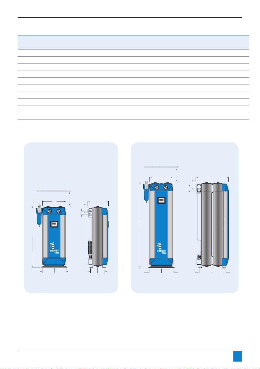
Section 3: Technical Data PD0046 - PD0360
Section 3: Technical Data PD0046 - PD0360
Dryer
model
Pipe
size
Inlet flow rate* Dimensions mm (inches)
Weight KgNo. of
cartridges
Recommended
Filter model
Filter
pipe size
Nm³/h
SCFM
ABCDEF
17745 655 (25.8) 76 (3) 50 (2) 600 (23.6) 50 2 ½
19455 735 (29) 76 (3) 50 (2) 700 (27.6) 58 2 ½
1 128 75 905 (35.6 76 (3) 50 (2) 850 (33.5) 66 2 ½
1 153 90 1030 (40.5) 76 (3) 50 (2) 1000 (39.4) 75 2
1 187 110 1260 (49.6) 76 (3) 50 (2) 700 (27.6) 105 4
1 255 150 1595 (62.8) 76 (3) 50 (2) 850 (33.5) 130 4 1
1 306 180 1845 (72.6) 76 (3) 50 (2) 1000 (39.4) 150 4 1
1½ 374 220 1262 (49.7) 76 (3) 62 (2.4) 700 (27.6) 250 8
1½ 510 300 1596 (62.8) 76 (3) 62 (2.4) 850 (33.5) 315 8
1½ 612 360 1845 (72.6) 76 (3) 62 (2.4) 1000 (39.4) 362 8 A159XA 1 ½
A
189189
175175
Models PD0046-PD0180
Models PD0220-PD0360
C
601601
B
A
175175
F
E
D
B
C
F
E
D
* Stated flows are for an inlet pressure of 7 barg (100 psig) with reference to 20°C (68°F), 1 barg (abs.), 0% relative water vapour pressure. For flow at other
pressures, apply the appropriate correction factors, terms and dewpoint.
380(15) 310 (12.2)
380(15) 310 (12.2)
380(15) 310 (12.2)
380(15) 310 (12.2)
380(15) 490 (19.3)
380(15) 490 (19.3)
380(15) 490 (19.3)
380(15) 310 (12.2)
380(15) 310 (12.2)
380(15) 310 (12.2)
Weight KgNo. of
cartridges
Recommended
Filter model
Filter
pipe size
A
189189
175175
Models PD0220-PD0360
B
C
F
E
D
Dryer
model
PD0046 1 77 45 655 (25.8) 380 (15) 310 (12.2) 76 (3) 50 (2) 600 (23.6) 46 2 A058XA ½
PD0056 1 94 55 735 (29) 380 (15) 310 (12.2) 76 (3) 50 (2) 700 (27.6) 51 2 A059XA ½
PD0075 1 128 75 905 (35.6) 380 (15) 310 (12.2) 76 (3) 50 (2) 850 (33.5) 62 2 A059XA ½
PD0090 1 153 90 1030 (40.5) 380 (15) 310 (12.2) 76 (3) 50 (2) 1000 (39.4) 70 2 A078XA ¾
PD0110 1 187 110 1260 (49.6) 380 (15) 325 (12.8) 76 (3) 50 (2) 700 (27.6) 85 4 A079XA ¾
PD0150 1 255 150 1595 (62.8) 380 (15) 325 (12.8) 76 (3) 50 (2) 850 (33.5) 105 4 A108XA 1
PD0180 1 306 180 1845 (72.6) 380 (15) 325 (12.8) 76 (3) 50 (2) 1000 (39.4) 122 4 A109XA 1
PD0220 1½ 374 220 1262 (49.7) 380 (15) 490 (19.3) 76 (3) 62 (2.4) 700 (27.6) 154 8 A128XA 1 ¼
PD0300 1½ 510 300 1596 (62.8) 380 (15) 490 (19.3) 76 (3) 62 (2.4) 850 (33.5) 195 8 A128XA 1 ¼
PD0360 1½ 612 360 1845 (72.6) 380 (15) 490 (19.3) 76 (3) 62 (2.4) 1000 (39.4) 225 8 A159XA 1 ½
* Stated ows are for an inlet pressure of 7 barg (100 psig) with reference to 20°C (68°F), 1 barg (abs.), 0% relative water vapour pressure. For
ow at other pressures, temperatures and dewpoints apply correction factors on page 13.
Inlet flow rate* Dimensions mm (inches)
Pipe
size
Nm³/hr SCFM A B C D E F
Weight KgNo. of
cartridges
Recommended
Filter model
Filter
pipe size
12
Page 13

Section 3: Technical Data PD0046 - PD0360
Dryer correction factors
Operating pressure (PCF)
barg
psig
Correction factor
4 5 6 7 8 9 10 11 12 13
58 72 87 100 115 130 145 160 174 189
0.62 0.75 0.87 1 1.12 1.25 1.37 1.5 1.62 1.75
Temperature (TCF)
Celcius °C
Farenheit °F
Correction factor
Pressure dewpoint (DCF)
Celcius °C
Farenheit °F
Correction factor
PRODRY Sizing Example
To correctly select the PRODRY model suitable for your application the following information is required: Minimum
Inlet Pressure, Maximum Inlet Temperature, Maximum Compressor Inlet Flow and Required Pressure Dewpoint (PDP).
Requirements Correction Factor
Maximum compressor inlet ow
Actual minimum inlet pressure
to the dryer
Maximum inlet temperature
Pressure dewpoint (PDP)
Corrected dryer ow rate
Appropriate Dryer Size
20 25 30 35 40 45 50
68 77 86 95 104 113 122
1.3 1.2 1.1 1 0.75 0.65 0.45
-20 -30 -40 -70 -74
-4 -22 -40 -94 -100
1.23 1.2 1 0.8 0.77
56 scfm -
6 barg PCF = 0.87
25°C (77°F) TCF = 1.2
-74°C (-100°F) DCF = 0.77
Inlet ow rate
PCF x TCF x DCF56(0.87 x 1.2 x 0.77)
Dryer model is selected based on the corrected ow rate, i.e. PD0075.
= =
69.7 scfm
(118 Nm³/hr)
Technical notes
Pre-filtration, including a water separator is essential to maintain dryer performance.
1.
An appropriate Water Separator must be installed. If bulk water enters the adsorption dryer it can cause heat
expansion to the desiccant, substantial rise in the dryer differential pressure, lead to poor outlet dewpoint, and
2.
cause potential dryer failure.
Walker Filtration recommends fitting an RXA dust filter to the outlet.
3.
Call your nearest Walker Filtration sales team for further information.
4.
13
Page 14
Section 4: Mechanical Installation
Mechanical Installation
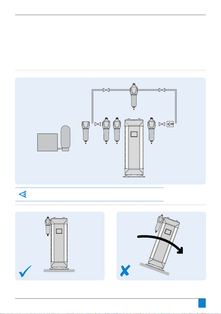
Figure 4.1: Typical installation
C
XA
To prevent back flow into the dryer a non-return valve should be placed in-line, downstream
of the dryer. This is essential when more than one dryer is used in a single application.
Figure 4.2: Level ground
WS X1 XA
RXA
14
Page 15
Section 4: Mechanical Installation
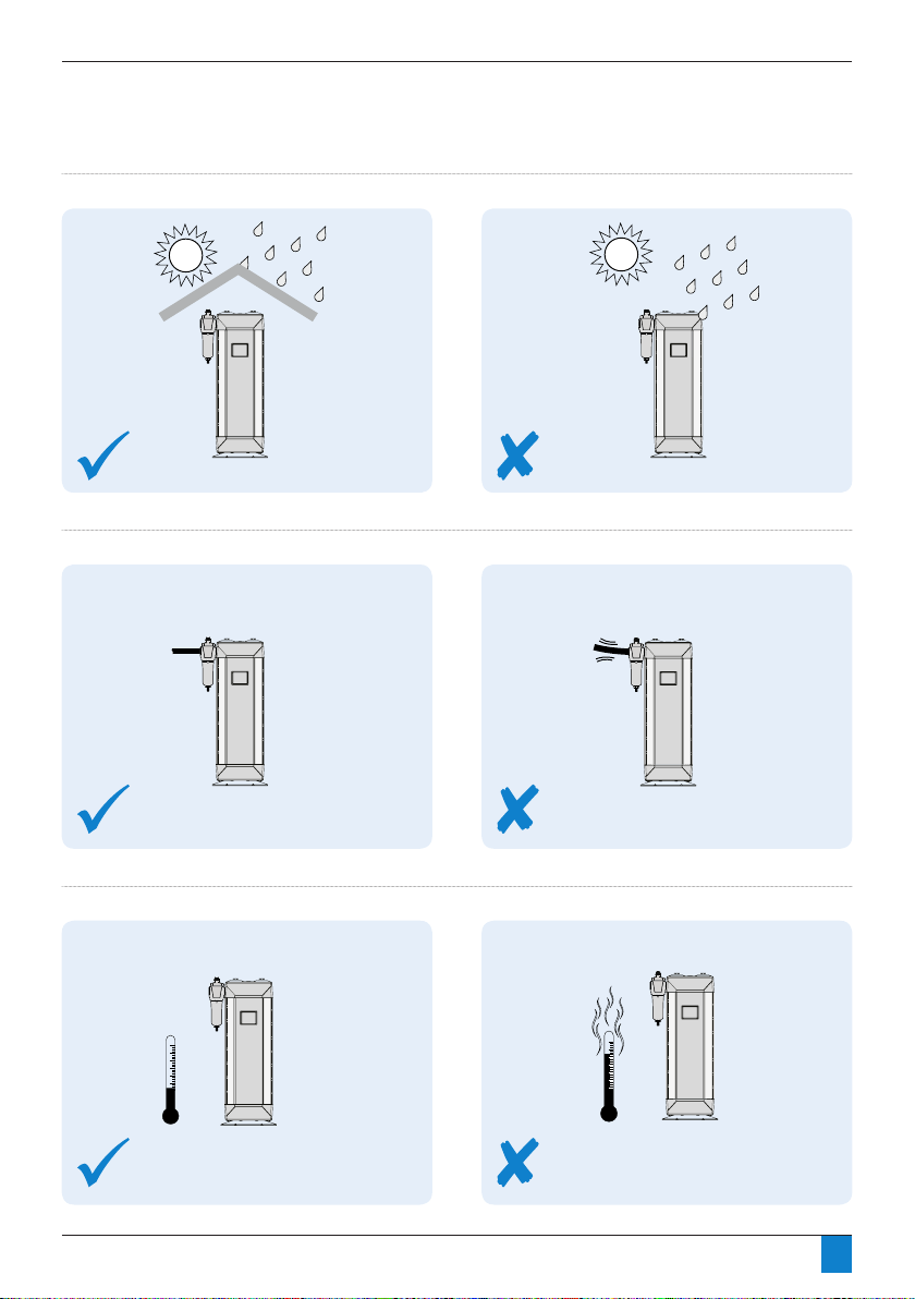
>Max 50OC (122OF)
Figure 4.3: Location
Figure 4.4: Hard piped installation
Figure 4.5 Exposure to heat
Max 50OC (122OF)
>Max 50OC (122OF)
15
Page 16
Section 4: Mechanical Installation
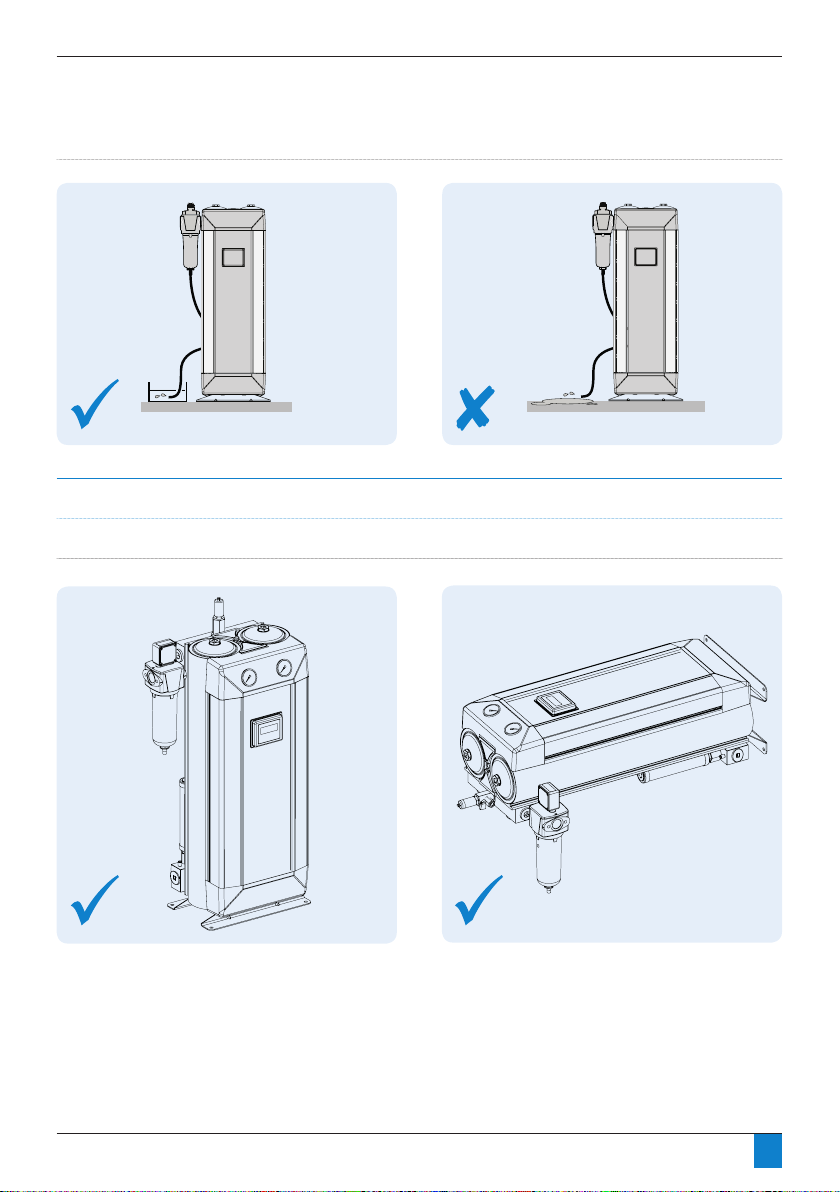
Figure 4.6: Drainage (all tubing should be secured up to the point of drain to prevent whipping during discharge)
Orientation
Figure 4.7: The PRODRY range of dryers is designed to operate in both vertical and horizontal orientation.
16
Page 17
Section 4: Mechanical Installation
Re conguration of the inlet / outlet ports
PD0046 – PD0360 models
• Dryer can be recongured to interchange position of
inlet and outlet ports as per gure 4.8.
• PRODRY has two inlet ports (A and B) and two outlet
ports (C and D). Either (A or B) can be used for inlet
and (C or D) for outlet. Make sure the un-used ports are
blanked off with provided pressure plugs.
Figure 4.8: Inlet/outlet ports
C
A
D
B
Any of the two outlet ports can be used on
Tools required
occasion. Please ensure flow at outlet should not
exceed specification. Please adhere to regional
regulations.
It is strongly advised to connect a non-return
valve to the outlet port of the dryer.
• Adjustable spanner
• Ratchet with 17mm Hexagonal connection
(PD0046 - PD0180)
• Ratchet with 1” Hexagonal connection
(PD0220 - PD0360)
Only use one inlet port at any one time
Ensure original seals are in place.
Check dryer is leak-free prior to operation.
17
Page 18
Section 4: Mechanical Installation
Figure 4.9: Co nnecting a pre- filter
Figure 4.9: Conn ecting a pre- filte r
Figure 4.10 : Conn ecting filte r dr ain
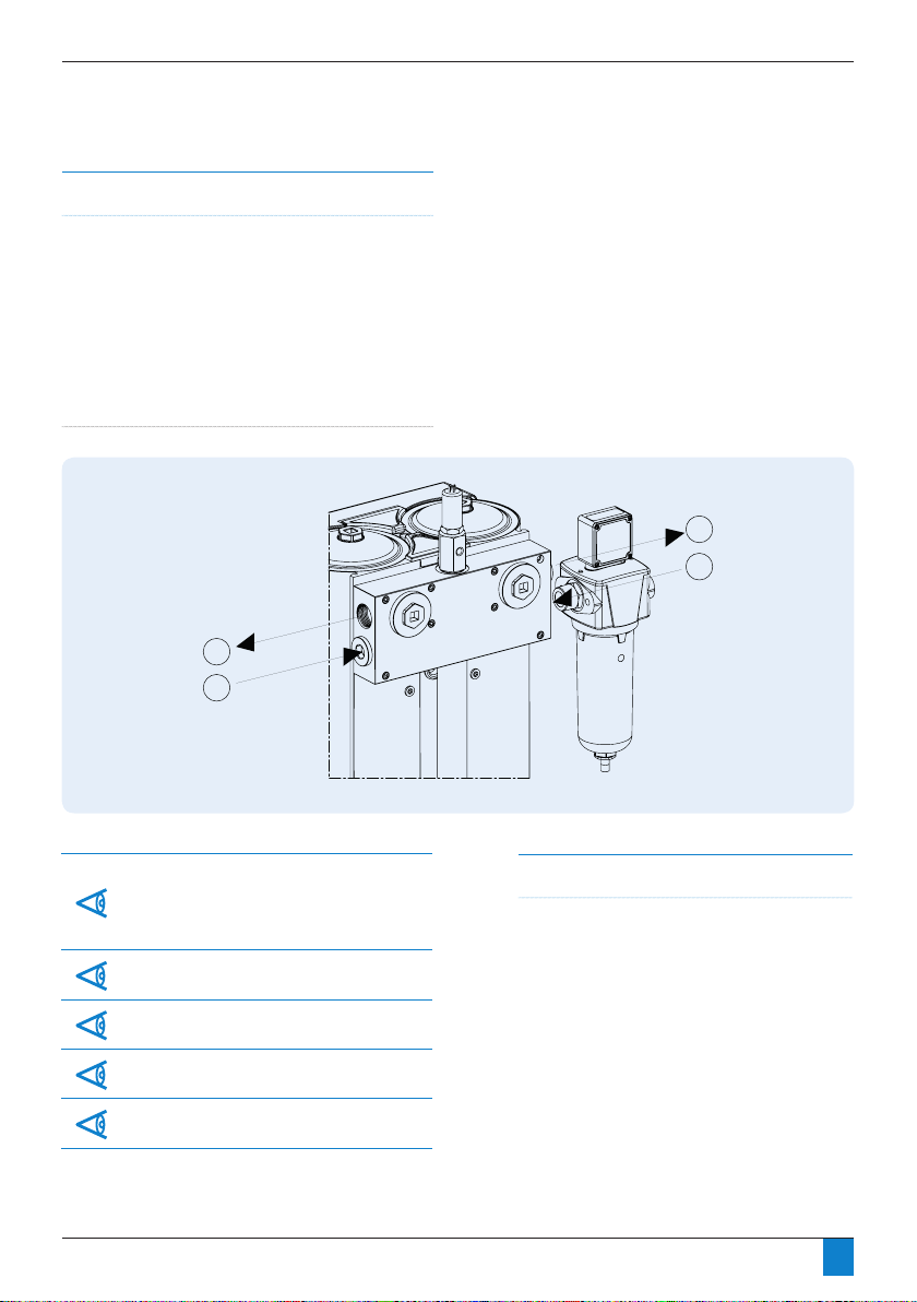
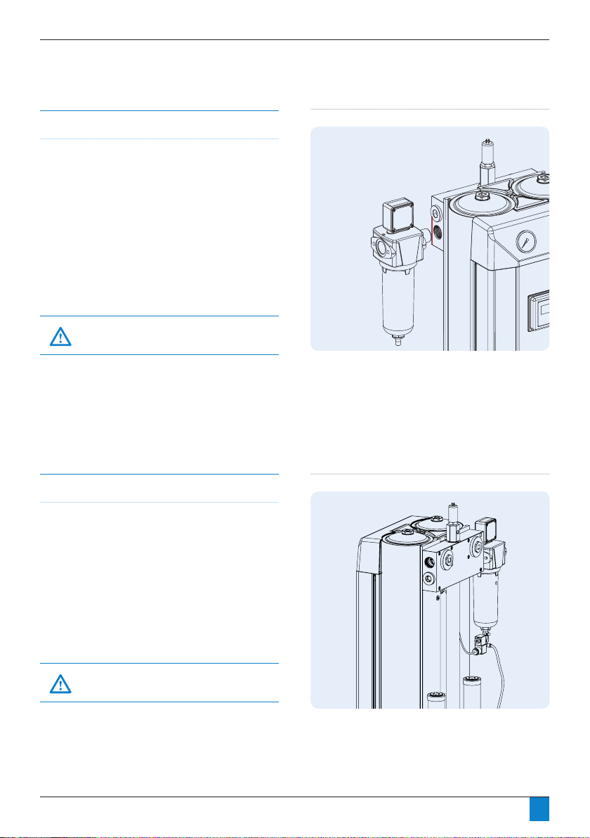
Connecting the pre-lter to the dryer
PD0046 – PD0360 models
• Attach pre-lter (purchased separately) utilising a pipe
nipple and/or pipe adapter.
• Pipe away condensate with tubing from drain outlet.
Ensure condensate is drained into an oil/water
separator.
• Fit any further ltration and/or ancillary equipment.
• Pre-lter is typically supplied with an autodrain installed
in the bowl drain port. On DMC models, this can
be replaced with a solenoid drain valve which is an
optional extra sold separately.
All tubing should be secured up to the point of
drain to prevent whipping during discharge.
• It is recommended that a bypass line including XA lter
is installed, as per gure 4.1.
Connecting the optional pre-lter drain valve
• Available on DMC models only.
• If necessary, remove existing autodrain valve from
pre-lter.
• Install pipe adapter into pre-lter drain port.
• Install optional solenoid drain valve onto pipe adapter(s)
taking care to note ow direction as indicated by arrow
etched into the side of the drain valve body.
• Pipe away condensate with tubing from drain outlet.
Ensure condensate is drained into an oil/water
separator.
Figure 4.9: Connecting a pre-filter
Figure 4.10: Connecting filter drain
All tubing should be secured up to the point of
drain to prevent whipping during discharge.
18
Page 19

Section 4: Mechanical Installation
Hygrometer
Sample Block
Hygrometer
Hygrometer
DIN Plug
PD0046 – PD0360 models
•
Installing the hygrometer (DMC models only)
•Remove hygrometer from packaging.
• Carefully remove plastic cover from the
sensor.
•
•
•
•
Hygrometer sample block is pre-installed in the dryer’s
top manifold assembly. Remove cover from threaded
port.
Confirm the threads on the hygrometer sample block
are clean and free from any dirt, water, cutting
lubricant, liquid thread sealant, oil and/or grease.
Per figure 4.11, insert hygrometer into the hygrometer
sample block and turn to clockwise to tighten .
Tighten
lightly with adjustable spanner.
Fit hygrometer DIN plug to the hygrometer and
tighten screw with pozi-head screwdriver.
Section 4: Mechanical Installation
Do not touch white sensor tube.
Open 2 full turns = 5Nl/min
Hygrometer Silencer Setting
Installing the hygrometer (DMC models only)
PD0046 – PD0360 models
• Remove hygrometer from packaging.
• Carefully remove plastic cover from the sensor.
Do not touch white sensor tube.
• Hygrometer sample block is pre-installed in the dryer’s
top manifold assembly. Remove cover from threaded
port.
• Conrm the threads on the hygrometer sample
block are clean and free from any dirt, water, cutting
lubricant, liquid thread sealant, oil and/or grease.
• Per gure 4.11, insert hygrometer into the hygrometer
sample block and turn to clockwise to tighten.
Tighten lightly with adjustable spanner.
• Fit hygrometer DIN plug to the hygrometer and tighten
screw with pozi-head screwdriver.
Figure 4.11 Attaching hygrometer
Figure 4.12 Hygrometer attached
Tools required
• Adjustable spanner
• Pozi-head screwdriver
19
Page 20

Section 4: Mechanical Installation
Purge Orice Size Identication
• Reference gure 4.13 and the Purge Plug Identication Table.
• Each dryer is pre-set with the correctly sized purge valve for an operating pressure of 7 barg (100 psig) at point of order.
• The lettering (A through S), located on the purge valve body, indicates the orice size selected to suit the operating pressure of
the dryer per the chart below.
• If the inlet pressure to the dryer will be different than the pre-set orice size, the purge valve can be adjusted.
• Most dryers use a single orice purge valve represented by the Blue and Green single letter references in the table below.
• Larger dryers may require a two or three hole purge valve as represented by the Red and Yellow two and three letter references.
• To select the correct orice size, locate the appropriate dryer model at the left side of the table and then the operating pressure
at the top.
• Make sure that the correct valve body (1, 2 or 3 hole) and orice disc (01, 02, 03 or 04) has been supplied with the dryer. The
discs have the number (01, 02, 03 or 04) stamped out at the top.
Purge Plug Identification
Operating
pressure
Dryer
PD0046
PD0056
PD0075
PD0090
PD0110
PD0150
PD0180
PD0220
PD0360
4 5 6 7 8 9 10 11 12 13
M K I H G F E E E D
P M L K J I H G F F
B S P M L L K I I H
C A P P N L K J I H
I E C A P M K K J I
CK M G F C B A S S P
EM CK P I G E C B A A
AFK FN DL P K H F E D C
EJP DIN CHM AFK AFK GP EM DL BJ AI
Disc
01
02
03
04
Every dryer is shipped with a purge orifice set up for 7 barg (100 psig) operation. The dryer will also include the necessary
purge valve components to configure the dryer to operate at any pressure from 4 barg (58 psig) to 13 barg (189 psig). For
example: A PD0150 dryer will be supplied with a single hole purge assembly with an 02 purge disc installed and indexed to
position F. Additional purge valve components will be included to allow the dryer to be configured to purge settings, CK, M,
H, D, B, A, S, P and N.
Appropriate purge plug selection is very important for function of the dryer. Failure to comply with this may affect your
warranty.
20
Page 21

Section 4: Mechanical Installation
Section 4: Mechanical Installation
Figure 4.13 Purge valve assembly
Orifice
Discs
Valve
Body
(Common to all dryers)
1 Hole Valve
Stem
2 Hole Valve Stem
Valve Control Spring
M4 Screw
3 Hole Valve Stem
Valve Stem O-ring(s)
(Fit into recess in
Valve Stem(s))
Gasket and Valve Stem are
rotated to align with index reference
letters on Valve Body
Index reference letters
Purge Sealing Gasket(s)
(1, 2 or 3 hole)
Disc
I.D.
Number
(01, 02, 03, 04)
Alignment
notches
Alignment
notches
3mm allen key
Figure 4.13 Purge valve assembly
Purge Valve Assembly
• Reference gure 4.13 and the Purge Plug Identication Table on Page 20.
• Once the correct purge body (1, 2 or 3 hole) and orice disc (01, 02, 03 or 04) has been selected per the instructions on Page
20, the purge valve may be assembled.
• The index letters located on the purge valve body correspond with the selected orice sizes per the Table on Page 20.
• Place the appropriate orice disc onto the valve body, taking care to align the notches. The disc will only t in one position.
• Place the valve stem O-ring(s) into their corresponding recesses on the back of the valve stem.
• Align the holes in the purge sealing gasket with the corresponding holes in the valve stem.
• Rotate the valve stem assembly so that the correct orice letters align with the notches corresponding to the holes (1, 2 or 3) in
the valve stem.
• Press the assembly together and fasten with the M4 screw.
• Double check to make sure that the open orice holes correspond with the correct orice selection as identied earlier.
21
Page 22

Section 5: Electrical Installation
Electrical Installation
PRODRY Controller power supply options
Models PD0046 - PD0360
• The dryer is designed to operate on either AC or DC
supply voltage dependant on controller option.
• Electrical wiring must comply with local regulations.
Voltage requirements must be conrmed to be within
the specication on the dryers rating plate.
• Ensure only one power source is connected at any one
time and is connected to the correct socket as shown in
gures 5.1 (LED Controller) and 5.2 (DMC Controller).
• The LED and DMC controller require a earth to be
connected within the DIN connector.
• The cable selection must suit local installation
regulations and be appropriate to power consumption
as shown in the Controller specication tables on pages
23 and 24.
PRODRY Recommended power cable specications
Controller Type
24VDC DMC 3
110/230VAC LED 3
Number
of cores
Cross Sectional
Area / AWG
0.75mm2 /
18 AWG
Recommended
Max. Length
3 Metres
Type
SJOW for Thermoset cable types
SVT and SJT for Thermoplastic cable types
or
Standard
Compliance
IEC 60227
or
IEC 60245
22
Page 23

Section 5: Electrical Installation
PIN OUTPUT
2
1
PIN
Earth
INPUT
N
L1 (110 VAC or 220 VAC*)
* Unit voltage rating must match supply voltage.
** Supplied from factory with jumper in female DIN
between pins 1 and 2.
12
3
12
POWER SUPPLYENERGY MANAGEMENT / ALARM
INPUT
N.C.
2
1
Energy Management Connections**
Alarm Connections
5VDC (+)
N.O.
3
12-24VDC
Section 5: Electrical Installation
Figure 5.1: LED Controlle r electrical connections
LED Controller Specifications
Ambient temperature 1.5°C to 50°C (35°F to 122°F)
Max. relative humidity 80% up to 31°C (88°F), decreasing linearly to 50% RH at 50°C (122°F)
Input voltage range (115V LED Controller) 115V, 50–60Hz,
Mains supply voltage not to exceed ±10% of nominal
Power Rating 16W (Max)
Input voltage range (230V LED Controller) 230VAC, 50-60Hz,
Mains supply voltage not to exceed 10% of nominal
Power Rating 16W (Max)
Protection class IP65
Transient over voltage IEC 60664 Class II
Pollution degree 2, IEC 60664
A circuit breaker or switch must be installed near the dryer. This should be easy to reach and shall be certified according to
EN60947-1 and EN60947-3. The switch or circuit breaker shall be marked as the disconn ecting device for th e dryer and needs
to be marked with on and positions.
Outp ut connections do not provide isolation from the mains connect ors and in terconnecting wiring must meet EN61010-1:2001
requireme nts for reinforced insulation.
LED Controller Specifications
Ambient temperature 5°C to 50°C (35°F to 122°F)
Input voltage range (115V LED Controller) 115V, 50–60Hz,
Input voltage range (230V LED Controller) 230VAC, 50-60Hz,
Protection class IP65
A circuit breaker or switch must be installed near the dryer. This should be easy to reach and shall be certified according
to EN60947-1 and EN60947-3. The switch or circuit breaker shall be marked as the disconnecting device for the dryer and
needs to be marked with on and off positions.
Figure 5.1: LED Controller electrical connections
Output connections do not provide isolation from the mains connectors and interconnecting wiring must meet EN610101:2001 requirements for reinforced insulation.
Mains supply voltage not to exceed ±10% of nominal
Mains supply voltage not to exceed 10% of nominal
Power Rating 16W (Max)
Power Rating 16W (Max)
23
Page 24

Section 5: Electrical Installation
2
3
24VDC (-)
Not used
Not used
Not used
N.O.
N.O.
Not used
Not used
Not used
Not used
Not used
Not used Not used
Not used
Not used Not used
Earth
1
PININPUT
INPUT
OUTPUT
OUTPUT
V.F.* OUTPUT
24VDC (+)
2
3
24 VDC (+)
24 VDC (-)
1
PIN
Signal (Hyg Pin 1)
Hygrometer Pin 2
Hygrometer Pin 3
2
3
1
PIN
24VDC (+)
2
3
* Volt Free
1
PIN
12-24VDC
OUTPUT
2
24VDC (-) Remote Valve Pin 2
1
PIN
24VDC (+) Remote Valve Pin 1
INPUT
INPUT
INPUT
1
2
3
1
2
3
1
2
3
1
2
3
1
2
POWER SUPPLY
HYGROMETER
ENERGY MANAGEMENT
ALARM
REMOTE DRAIN VALVE
Section 5: Electrical Installation
Figure 5.2: DMC Controller electrical connections
DMC Controller Specifications
Ambient temperature1.5°C to 50°C (35°F to 122°F)
Max. relative humidity 80% up to 31°C (88°F), decreasing linearly to 50% RH at 50°C (122°F)
Input voltage range (24VDC DMC Controller)
24VDC
Power Rating 16W (Max)
Protection class IP65
Transient over voltage IEC 60664 Class II
Pollution degree 2, IEC 60664
A circuit breaker or switch must be in stalled near the dryer. This should be easy to reach and shall be certified according to
EN60947-1 and EN60947-3. The switch or circuit breaker shall be marked as the disconnecting device for th e dryer and needs
to be marked with on and
positions.
Output co nnections do no t provide isolation from the mains connectors and in terconnecting wiring must meet EN61010-1:2001
requireme nts for reinforced insulation.
1-green
control
2-blue
3-red
1-brown
2-blue
DMC Controller Specifications
Ambient temperature 5°C to 50°C (35°F to 122°F)
Input voltage range (24VDC DMC Controller) 24VDC
Protection class IP65
Figure 5.2: LED Controller electrical connections
A circuit breaker or switch must be installed near the dryer. This should be easy to reach and shall be certified according
to EN60947-1 and EN60947-3. The switch or circuit breaker shall be marked as the disconnecting device for the dryer and
needs to be marked with on and off positions.
Output connections do not provide isolation from the mains connectors and interconnecting wiring must meet EN610101:2001 requirements for reinforced insulation.
Power Rating 16W (Max)
24
Page 25

Section 5: Electrical Installation
20 mm
3 mm
Outer insulation
must extend
through grommet
to ensure that
IP65 specification
is met
Gasket
Insert
Case
Grommet
Washer
Cable
Cable Gland
How to wire a DIN connector
Models PD0046 - PD0360
• Locate the DIN connector on the back of the controller.
• Remove the screw completely from the centre of the
connector.
• Remove the blanking plug, if present, from the
connector and discard.
• Insert a small at screwdriver into the small recess at
the edge of the insert, pry the insert out of the DIN
connector’s outer shell per gure 5.3.
• Per gure 5.4, slip cable end through DIN connector’s
cable gland, washer, grommet and out through the
front of the DIN connector case.
Cable diameter should be no greater than 6mm
(1/4”). Larger diameters do not fit well into the
cable gland of the DIN connectors.
Cable should be round as rectangular cable
or ribbon cable will not seal properly in DIN
connectors grommet.
• Strip the outer insulation of the cable back approx
20mm (3/4”).
• Strip the conductor insulation back approx 3mm (1/8”).
• Insert conductors into appropriate pins of insert.
Tighten retaining screws securely.
• Determine which direction the cable gland should
point.
• Carefully pull the cable back through the case until the
insert snaps back into place. Take care to work the wires
around the retaining screw hole as they can become
fairly easily pinched.
• Plug the DIN connector back onto the appropriate
electrical connection on the back of the dryer’s
controller per gure(s) 5.1 and 5.2. Take care to make
sure that sealing gasket is in place.
The male ground pin is slightly wider than
pins 1 & 2. Take care to ensure that the female
connector is oriented correctly.
Figure 5.3: DIN connector
Figure 5.4: DIN connector for LED and DMC Controller
25
Page 26

Section 5: Electrical Installation
LED Controller
Pin 3
Pin
1
2
3
DC Power
Supply
(Field Installed)
Remote
Visual or
Audible
Indicator
(Field Installed)
-VDC
+VDC
LED Controller
Pin 3
Pin
Pin 1
Pin 2
DMC
Controller
1
2
3
1
2
3
DC Power
Supply
(Field Installed)
Remote
Visual or
Audible
Indicator
(Field Installed)
-VDC
+VDC
+24VDC
-24VDC/COM
Remote
Visual or
Audible
Indicator
(Field Installed)
Alarm connection details
Models PD0046 - PD0360
• To enable the alarm facility, it is recommended that a
suitable cable is brought into the controller via the rear
panel with a grommet. An external power source is
required.
• Per Figures 5.5 (LED Controller) or 5.6 (DMC Controller),
connect the switching pole of an externally powered
alarm indication device to the corresponding terminals
of the controller’s alarm output.
For details regarding wiring of female DIN
connector refer to “How to wire a DIN connector”
on page 25.
Hirschmann GDS 207 industrial std DIN connector
Alarm Contact Rating (LED Controller) 3.0 AMPS 28VDC
Alarm Contact Rating (DMC Controller) 0.5 AMPS 24VDC
Alarm Connection Details
or equivalent
Fig 5. 5 Alarm contact connections (LED Controller)
Fig 5.6 Alarm contact connections (DMC Controller)
26
Page 27

Section 6: Operation
Detailed Operational Description - DMC Controller
•
•
•
•
•
•
•
Figure 6.1: Dewp oint selection switch cont rol
Range 2: -40° (-40°F)
Required outlet pressure dewpoint:
Purge turn on value:
Range 3: -74°C (-100°F)
Required outlet pressure dewpoint:
Purge turn on value:
DMC Controller operates on a standard timed cycle as detailed
Operational status is displayed in text form on the LCD display.
Range 1: -20°C (-4°F)
Required outlet pressure dewpoint:
Purge turn on value:
-20°C (-4°F)
-23°C (-9.4°F)
-21°C (-5.8°F)
-40°C (-40°F)
-43°C (-45.4°F)
-11°C (-41.8°F)
-74°C (-100°F)
-76°C (-104.8°F)
-74°C (-100 °F)
When installed, a hygrometer allows the DMC controller to shut
selectable dewpoint ranges. The ranges are controlled by a
switch located on the upper back side of the DMC controller as
Operation
Background / Function of the dryer
PRODRY is designed to provide a smooth, controlled and
uninterrupted delivery of dry compressed air. Wet air passes
through a pre-lter and travels down to the bottom valve
assembly. The air is then fed through the bottom of the
desiccant bed and moves through the high performance
desiccant until it becomes dry. On exit from the desiccant
cartridge, the air is passed through the outlet valve assembly.
During this process, the dryer control system cycles the process
air between the two desiccant towers. While one tower is on
stream removing water vapour, the other is being carefully
depressurised in preparation for regeneration. The desiccant
bed is regenerated by expanding a small amount of dry
process air, or purge air, through the saturated desiccant.
Purge air passes to atmosphere through the silencer, which is
tted to an exhaust valve. The chamber is then repressurised,
with the control system assuring each chamber is at full
operational pressure prior to changeover.
This ensures a reliable and efcient operation. The air stream is
switched and the cycle repeats on a continuous basis.
Detailed Operational Description - LED Controller
• Refer to detailed operational schematics, gure(s)
6.3 - 6.8.
• LED Controller operates on a standard timed cycle as
detailed in Figures 6.3 through 6.8.
• Panel LED’s illuminate to indicate various service
warnings, refer to Troubleshooting in Section 11 for
specic details.
• To reduce purge loss during periods of low and / or no
air demand the Energy Management feature may be
utilised. A detailed description is given in Section 7.
• For remote indication of any faults, the Alarm Contacts
may be utilised to send a signal to a light or remote
service panel. Further details are given on page 26.
Detailed Operational Description - DMC Controller
• Refer to detailed operational schematics, gure(s) 6.3
- 6.8.
• DMC Controller operates on a standard timed cycle as
detailed in Figures 6.3 through 6.8.
• Operational status is displayed in text form on the LCD
display.
• When installed, a hygrometer allows the DMC controller
to shut off the purge when the outlet dewpoint is within
one of three selectable dewpoint ranges. The ranges are
controlled by a switch located on the upper back side of
the DMC controller as detailed in gure 6.1.
• Range 1: -20°C (-4°F)
Required outlet pressure dewpoint:
Purge shut off value:
Purge turn on value:
• Range 2: -40° (-40°F)
Required outlet pressure dewpoint:
Purge shut off value:
Purge turn on value:
• Range 3: -74°C (-100°F)
Required outlet pressure dewpoint:
Purge shut off value:
Purge turn on value:
Figure 6.1: Dewpoint selection switch control
-20°C (-4°F)
-23°C (-9.4°F)
-21°C (-5.8°F)
-40°C (-40°F)
-43°C (-45.4°F)
-41°C (-41.8°F)
-74°C (-100°F)
-76°C (-104.8°F)
-74°C (-100°F)
If the hygrometer is not installed, the DMC controller
will default to the standard timed cycle of operation.
27
Page 28

Section 6: Operation
Section 6: Operation
•
•
s
s
•
Please note that the Energy Management feature should
not be used when a hygrometer is installed in the dryer.
A
C
B
D
• If not utilising a hygrometer, purge loss may be reduced during periods of low or no air demand the
Energy Management Feature (EM) may be utilised. A detailed description is given in Section 7.
Please note that the Energy Management feature should not be used when a hygrometer is
installed in the dryer.
• For remote indication of any electrical faults, the Alarm Contacts may be utilised to send a signal to a
light or remote service panel. Further details are given on page 26.
• An optional pre-lter drain solenoid valve is available for the DMC controller. When installed per gure
4.10, the drain will open for 2 seconds at the beginning of each cycle. Operational schematic, gure
6.8 provides additional detail.
Figure 6.2: Typical installation
Start-up procedure
• Refer to gure 6.2
• Close valves A, B, C and D.
• Switch on compressor.
• Open valve A slowly.
• Check there are no leaks from the dryer
• Switch on electric power, the panel will display the
operational features.
• The dryer will enter standard cycle mode.
On initial commissioning, only run the dryer for
a minimum of 6 hours to ensure dewpoint is
adequate.
• Open valve B slowly.
Shut-down Procedure
• Close valve B.
• Close valve A.
• Leave dryer running for 15 minutes to fully depressurise.
• Switch off all electrical power to the dryer.
Under no circumstances must compressed air
be allowed to flow through the dryer following
switch off of electrical power. This will result in
terminal failure of the desiccant cartridges and
regeneration will not be possible.
28
Page 29

Section 6: Operation
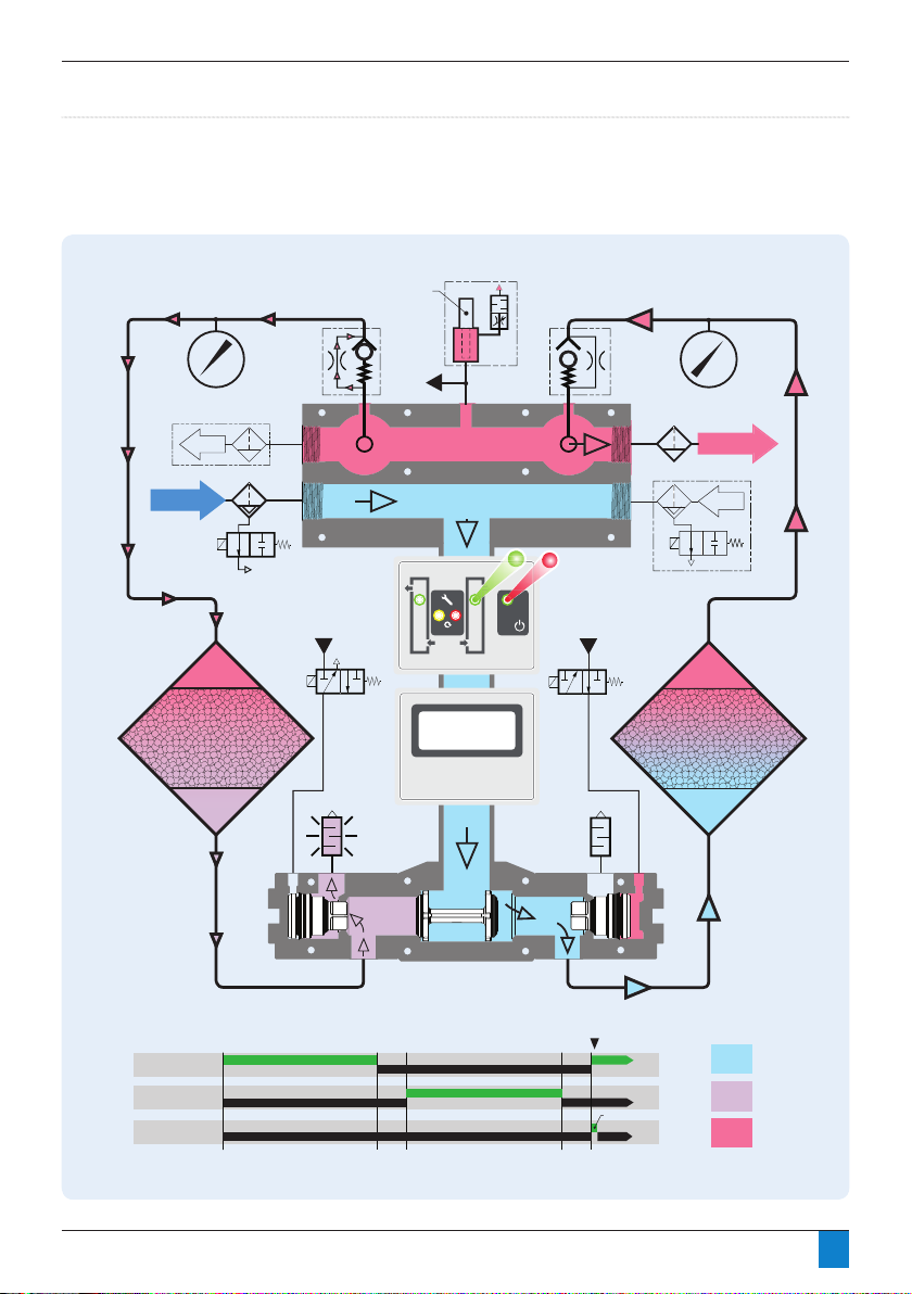
Figure 6.3: Initial Pressurisation (Power Off)
• With power off to the dryer, both towers pressurise to line pressure. All valves remain closed and the dryer remains air tight
(with the exception of a small bleed of air from the hygrometer sample block).
• Note: Any air owing through dryer, passes through both towers.
29
Page 30

Section 6: Operation
Figure 6.4: Stage 1: Left Tower Purging, Right Tower Drying
• After an initial 40 second delay, the left solenoid valve opens allowing the left exhaust shuttle valve to open. Air rushes from the
left tower out the silencer as it depressurises. For 120 seconds, a bleed of dry air from the outlet of the on-stream (right) tower
is directed through the left purge orice and down through the left tower to regenerate the off stream (left) desiccant bed.
30
Page 31

Section 6: Operation
Figure 6.5: Stage 2: Repressurisation
• At the completion of Stage 1, the left solenoid closes and the left tower repressurises for 25 seconds.
• Note: Any air owing through dryer, passes through both towers.
31
Page 32

Section 6: Operation
Figure 6.6: Stage 3: Left Tower Drying, Right Tower Purging
• At the completion of Stage 2, the right solenoid valve opens allowing the right exhaust shuttle valve to open. Air rushes
from the right tower out the silencer as it depressurises. For 120 seconds, a bleed of dry air from the outlet of the on-stream
(left) tower is directed through the right purge orice and down through the right tower to regenerate the off stream (right)
desiccant bed.
32
Page 33

Section 6: Operation
Figure 6.7: Stage 4: Repressurisation
• At the completion of Stage 3, the left solenoid closes and the left tower repressurises for 25 seconds.
• Note: Any air owing through dryer, passes through both towers.
33
Page 34
Section 6: Operation
A
INLET
OUTLET
Purge
Control
Non-Return
Valve
Purge
Control
Non-Return
Valve
To Drain Point
A
A
ON
OFF
ON
Wet
Purge
Dry
OFF
SV 2
(Right Solenoid Control Valve)
LEGEND:
SV 1
(Left Solenoid Control Valve)
ON
OFF
DV 1
(Prefilter Drain Solenoid Valve)
Seconds: 0 120 154 274308
Alternate Outlet Position
Alternate Inlet Position
RX-1
After Filter
2 Seconds
RESET
Standard Running Mode
-
Hours Run 456
Service History # 0
31
2
31
2
Left
Solenoid
Control Valve
Silencer Silencer
Right
Solenoid
Control Valve
LED
Controller
DMC
Controller
XA Pre-Filter
DV1 Optional
Drain Valve
(Optional on
DMC Models Only)
Left Tower
Pressure Gauge
Right Tower
Pressure Gauge
Left
Desiccant
Tower
Right
Desiccant
Tower
Hyg
Sample
Cell
Optional Hygrometer
(DMC Models Only)
TIMING CHART:
SV1 SV2
Figure 6.8: Drain Valve Activation
• At the completion of Stage 4, the dryer moves back to Stage 1.
• The drain valve opens at the beginning of the cycle (Stage 1) for a period of 2 seconds.
34
Page 35

Section 7: Energy Management
Fig 7. 1 Manu al switch purge contro l (LED Controller)
The following schemati
er an overview
of the devices mentioned as they might be connected for use in
details d er between device ma nufacturers, so in all cases th e
N.C.*
Manual Switch
(Field Installed)* Normally Closed, open to turn purge off
LED Controller
Pin 1
(Puts out
+5 VDC
signal)
Pin 2
Signal Out to Switch
Signal Back
1
2
3
Fig 7. 1 Manu al switch purge contro l (LED Controller)
The following schemati
er an overview
of the devices mentioned as they might be co nnected for use in
details d er between device manufacturers, so in all cases the
N.C.*
Manual Switch
(Field Installed)* Normally Closed, open to turn purge off
LED Controller
Pin 1
(Puts out
+5 VDC
signal)
Pin 2
Signal Out to Switch
Signal Back
Fig 7.2 Ma nual switch purge contro l (DMC Controller)
N.O.*
Signal Out to Switch (+24 VDC)
Manual Switch
(Field Installed)* Normally open, close to turn off purge
Pin 1
Pin 2
Signal Out to Switch
Signal Back
DMC
Controller
1
2
3
1
2
3
Energy Management
Please note that the Energy Management feature
should not be used when a hygrometer is
installed in the dryer.
Overview
Regenerative dryers must expel a portion of the process air
in order to free themselves of accumulated moisture. During
periods of low air demand, however, this air loss is not
necessary and is therefore undesirable. In many cases, the
compressor runs almost continuously in order to keep up with
the dryer’s purge loss.
All Walker Filtration dryers are equipped with an Energy
Management feature that allows the purge to be shut off
during periods of low or no demand. The dryer controller
is tted with a set of eld accessible contacts, that can be
employed to shut off the solenoid valves which control the
purge function of the dryer, therefore eliminating any air loss
from the dryer.
Developing a Purge Control Strategy
In order to utilise this function, the operator must provide a
switching system that provides acceptable logic to indicate to
the dryer that there is little or no air demand. On the following
pages, some examples of commonly used switching systems
are provided in ascending order of complexity.
Using a Manual Switch for Purge Control
The simplest of arrangements, a manual switch may be
employed to shut the purge off when the air downstream of
the dryer is not being used. Commonly used on point of use
systems. For example, if the dryer is only used to supply air of
an appropriate dryness to a specic machine or application,
the dryer will only be required when the machine is in use and
may be shut off either manually or possibly via extra contacts
provided in the machine’s on/off switch.
It is extremely important to understand that the purge may
only be shut off during periods of low or no demand. This
feature, if used otherwise, can result in permanent damage
to the desiccant beds resulting in loss of drying capacity
and possibly mechanical failure. The cartridges must not be
allowed to become fully saturated at any time.
The following schematic ( Fig 7.1) offers an overview of the
devices mentioned as they might be connected for use in
controlling a dryer’s purge function. Please note that specic
details differ between device manufacturers, so in all cases the
manufacturer’s specications should be adhered to.
Fig 7. 1 Manual switch purge control (LED Controller)
Fig 7.2 Manual switch purge control (DMC Controller)
35
Page 36

Section 7: Energy Management (LED Controller)
Fig 7. 3 Standard pressure switch purge contro l (LED Controller)
Pressure Switch
(Field Installed)* Normally Closed, open to turn purge off
LED Controller
Pin 1
(Puts out
+5 VDC
signal)
Pin 2
Signal Out to Switch
Signal Back
1
2
3
N.C.*
N.O.
Fig 7. 3 Standard pressure switch purge contro l (LED Controller)
Pressure Switch
(Field Installed)* Normally Closed, open to turn purge off
LED Controller
Pin 1
(Puts out
+5 VDC
signal)
Pin 2
Signal Out to Switch
Signal Back
Fig 7.4 Standard pressure switch purge contro l (DMC Controller)
(Field Installed)* Normally open, close to turn off purge
Pin 1
Signal Out to Switch (+24 VDC)
Pin 2
Signal Out to Switch
Signal Back
DMC
Controller
1
2
3
1
2
3
N.C.*
N.O.
N.C.
N.O.*
Pressure Switch
Using a Standard Pressure Switch for Purge Control
Many compressors come equipped with pressure switches
with extra contacts that can be utilised to switch off the
dryer’s purge when the compressor is in an unloaded state.
Unfortunately, many of these switches have signicantly large
dead bands (difference between the load (on) and unload (off)
settings that in most cases cannot be altered). The amount of
air that can pass downstream, through the dryer, while the
compressor is unloaded must be taken into consideration as it
can be signicant, especially if there is a large dead band and/
or large wet receiver.
Often, a stand-alone pressure switch is a better option
as it allows the user to adjust it independently from the
compressor’s pressure switch. When selecting a stand-alone
pressure switch, the smaller the dead band the better.
When using a stand-alone pressure switch, the dryer is wired
into the normally closed (LED Controller) or normally open
(DMC Controller) contacts on the pressure switch. When the
switch is actuated (at 100 psig in the example), the purge
shuts off until the pressure switch deactuates (at 95 psig in
example). The point at which the switch deactuates, may be
adjusted to suit the system.
If it is determined that the dewpoint drops to an unacceptable
level, the deactuation point must be increased. Please note
that with most standard pressure switches, the dead band is
xed such that the activation and deactuation points move
together.
It is extremely important to understand that the purge may
only be shut off during periods of low or no demand. This
feature, if used otherwise, can result in permanent damage
to the desiccant beds resulting in loss of drying capacity
and possibly mechanical failure. The cartridges must not be
allowed to become fully saturated at any time.
Figures 7.3 and 7.4 offer an overview of the devices
mentioned as they might be connected for use in controlling
a dryer’s purge function. Please note the specic details
differ between device manufacturers, so in all cases the
manufacturer’s specications should be adhered to.
Fig 7. 3 Standard pressure switch purge control (LED Controller)
Fig 7.4 Standard pressure switch purge control (DMC Controller)
36
Page 37

Section 7: Energy Management
signal)
Using an elec tronic pressure switch for purg e cont rol
The best choice if using a pressure switch is to select an
electronic programmable type pressure switch which is
effectively a pressure transmitter an d process controller
a standard pressure switch, an electronic programmable
pressure switch can be setup to provide a much more
customised operation. Typically, the dead band can be
reduced or eliminated so that an immediate reaction to
It is extremely important to understand that th e purge may
only be shut
during periods of low or no demand. Th is
feature, if used otherwise, can result in permanent damage
to the desiccant beds resulting in loss of drying capacity
and possibly mech anical failure. Th e cartridges must not be
allowed to become fully saturated at any time.
an overview of the devices
mentioned as they might be connected for use in controlling
d er between device manufacturers, so in all cases the
Se ctio n 7: Energy Management
This setup is for example only. This configuration can be
amended, depending on application.
SYSTEM PRESSURE (psig)
PURGE ON (switch deactivated) PURGE ON (switch deactivated)
PURGE OFF (switch activated)
PURGE OFF
ON
OFF
105
100
95
90
85
85
80
ADJUST TO SUIT SYSTEM
(pressure switch deactivation point)
Fig 7.5 Pressu re switch setting
DC Power
Supply
-VDC (COM)
+VDC
+VDC
Output
COM
Electronic
Pressure Switch
Relay
N.C.*
Figure 7.6 Electr onic press ure switc h f or purge co ntro l (LED Cont)
Figure 7.7 Electr onic pressure switch for purge co ntro l (DMC Cont)
* Normally open, close to turn off purge
Pin 1
Pin 2
Signal Out to Switch (+24VDC)
DMC
Controller
1
2
3
* Normally Closed, open to turn purge off
Signal Back
DC Power
Supply
-VDC (COM)
+VDC
+VDC
Output
COM
Electronic
Pressure Switch
Relay
N.O.*
Signal Back
LED Controller
Pin 1
(Puts out
+5 VDC
signal)
Pin 2
1
2
3
signal)
only be shut
during periods of low or no demand. Th is
feature, if used otherwise, can result in permanent damage
to the desiccant beds resulting in loss of drying capacity
and possibly mech anical failure. Th e cartridges must not be
allowed to become fully saturated at any time.
an overview of the devices
mentioned as they might be connected for use in controlling
d er between device manufacturers, so in all cases the
This setup is for example only. This configuration can be
amended, depending on application.
PURGE OFF
ADJUST TO SUIT SYSTEM
Figure 7.7 Electr onic pressure switch for purge co ntro l (DMC Cont)
* Normally open, close to turn off purge
Pin 1
Pin 2
Signal Out to Switch (+24VDC)
DMC
Controller
1
2
3
DC Power
Supply
-VDC (COM)
+VDC
+VDC
Output
COM
Electronic
Pressure Switch
Relay
N.O.*
Signal Back
signal)
Se ctio n 7: Energy Management
SYSTEM PRESSURE (psig)
PURGE ON (switch deactivated) PURGE ON (switch deactivated)
PURGE OFF (switch activated)
PURGE OFF
ON
OFF
105
100
95
90
85
85
80
ADJUST TO SUIT SYSTEM
(pressure switch deactivation point)
Fig 7.5 Pressu re switch setting
Figure 7.5: Typical installation
Using an Electronic Pressure Switch for Purge Control
The best choice if using a pressure switch is to select an
electronic programmable type pressure switch which is
effectively a pressure transmitter and process controller
built into one device. While signicantly more costly than
a standard pressure switch, an electronic programmable
pressure switch can be setup to provide a much more
customized operation. Typically, the dead band can be
reduced or eliminated so that an immediate reaction to
system pressure in system indicating air ow, can
be obtained.
Figure 7.6 Electronic pressure switch for purge control (LED Controller)
It is extremely important to understand that the purge may
only be shut off during periods of low or no demand. This
feature, if used otherwise, can result in permanent damage
to the desiccant beds resulting in loss of drying capacity
and possibly mechanical failure. The cartridges must not be
allowed to become fully saturated at any time.
Figures 7.6 and 7.7 offer an overview of the devices
mentioned as they might be connected for use in controlling
a dryer’s purge function. Please note that specic details
differ between device manufacturers, so in all cases the
manufacturer’s specications should be adhered to.
This setup is for example only. This configuration
can be amended, depending on application.
Figure 7.7 Electronic pressure switch for purge control (DMC Controller)
37
Page 38

Section 7: Energy Management
Process Controller
Dewpoint
Transmitter
Relay
Signal
+VDC
COM
N.C.*
Figure 7.8 : Process controller & hygrometer (LED Controller)
DC Power
Supply
-VDC (COM)
+VDC
+VDC
COM
Signal In
Signal Out
* Normally Closed, open to turn purge off
Signal Back
Signal Out
LED Controller
Pin 1
(Puts out
+5 VDC
signal)
Pin 2
1
2
3
Process Controller
Dewpoint
Transmitter
Relay
Signal
+VDC
COM
N.C.*
Figure 7.8 : Process controller & hygrometer (LED Controller)
Figure 7.9 : Process controller & hygrometer (DMC Controller)
DC Power
Supply
-VDC (COM)
+VDC
+VDC
COM
Signal In
Signal Out
* Normally Closed, open to turn purge off
Signal Back
Signal Out
LED Controller
Pin 1
(Puts out
+5 VDC
signal)
Pin 2
1
2
3
Process Controller
Dewpoint
Transmitter
Relay
Signal
+VDC
COM
N.O.*
DC Power
Supply
-VDC (COM)
+VDC
+VDC
COM
Signal In
Signal Out
Signal Back
Signal Out
Pin 1
Pin 2
Signal Out to Switch (+24VDC)
DMC
Controller
1
2
3
* Normally open, close to turn off purge
Using a hygrometer and process controller for
purge control
The best option for purge control if the delivered dryness
(pressure Dewpoint) of the air from the dryer is critical. If the
air is deemed dry enough, than the purge can be shut off until
the air’s moisture starts to climb. If the purge is turned off,
care must be taken to ensure that the desiccant beds are not
allowed to wet out too far before the purge is turned back
on. Also, after turning the purge back on, the air’s pressure
Dewpoint may increase a bit before starting to drop again.
This should be taken into consideration to ensure that the air
ow remains sufciently dry.
It is extremely important to understand that the purge may
only be shut off during periods of low or no demand. This
feature, if used otherwise, can result in permanent damage
to the desiccant beds resulting in loss of drying capacity
and possibly mechanical failure. The cartridges must not be
allowed to become fully saturated at any time.
Figures 7.8 and 7.9 offer an overview of the devices
mentioned as they might be connected for use in controlling
a dryer’s purge function. Please note that specic details
differ between device manufacturers, so in all cases the
manfacturer’s specications should be adhered to.
Making connections between a switching device &
dryer Energy Management contact
Cable / Wire Selection Criteria:
Selected wire should have:
At least 2 conductors. More conductors can be useful in
the case of a conductor break. Conductors can be swapped
without having to run new cable.
• A conductor gauge of no greater than 18 awg is
• An outside diameter of no greater than 6mm (1/4”).
• An insulation type compatible with the environment that
recommended to t comfortably into the DIN connector
insert.
Larger diameters do not t well into the cable gland of the
EM DIN connectors.
it will be run in.
Figure 7.8: Process controller & hygrometer (LED Controller)
Figure 7.9: Process controller & hygrometer (DMC Controller)
This setup is for example only. This configuration
can be amended, depending on application.
38
Page 39

Section 7: Energy Management
Figure 7.11 : Connecting to EM port (LED Controller)
LED Controller
EM Port
Figure 7.11 : Connecting to EM port (LED Controller)
DMC
Controller
LED Controller
EM Port
Figure 7.12 : Connecting to EM port (DMC Controller)
EM Port
Figure 7.11 : Connecting to EM port (LED Controller)
Figure 7.13 : Din co nnector for LED and DMC Controller
DMC
Controller
LED Controller
EM Port
Figure 7.12 : Connecting to EM port (DMC Controller)
EM Port
20 mm
3 mm
Outer insulation
must extend
through grommet
to ensure that
IP65 specification
is met
Gasket
Insert
Case
Grommet
Washer
Cable
Cable Gland
Se ctio n 7: Energy Management
Making connections between a switching device and dryer
Energy Management contact.
•
check continuity at the dryer end before connecting to the
dryer. Make sure that the co ntacts on the switch are normally
closed for the LED Controller and normally open for the DMC
Controller. Pi n 1 of the dryer EM co nnection puts out a 5 VDC
signal on the LED Controller and 24VDC on the DMC Controller.
Take care to ensure that the contacts on the switching
device are ‘dry’ and free of any voltage which could harm the
dryer controller.
•Locate the DIN connector on the ba ck of the controller
(Figure(s) 7.11 and 7.12).
•Remove the screw completely from the centre of the
connector.
•Remove the blanking plug from the connector and discard.
of the insert, pry the insert out of the DIN connectors outer
shell per
ure 7.10.
•
•For LED Controller, remove the jumper wire which is between
plug 1 and 2 and di scard.
•Slip cable en d through DIN connector’s cable gland, washer,
grommet and out through the front of the DIN connector case.
•Strip the outer insulation of the cable back a
pprox 20mm
(3/4”).
•Strip the conductor insulation back approx 3mm (1/8”).
•If possible using a meter, ve rify the switch function.
•Insert conductors into pins 1 & 2 of insert. Tighten retaining
screws securely.
•Determine which direction the cable gland should point.
•Carefully pull the cable back through the shell until the insert
snaps back into place. Take care to work the wires around the
retaining screw hole as they can become fairly easily pinched.
•Plug the DIN connector back onto the dr yer’s EM co nnection
taking care to make sure that sealing gasket is in place.
Figure 7.10: DI N conn ecto r
Figure 7.11 : Connecting to EM port (LED Controller)
Figure 7.13 : Din co nnector for LED and DMC Controller
DMC
Controller
LED Controller
EM Port
Figure 7.12 : Connecting to EM port (DMC Controller)
EM Port
The male ground pin is slightly wider than pins 1 & 2.
Take care to ensure that the female connector is
oriented corectly.
20 mm
3 mm
Outer insulation
must extend
through grommet
to ensure that
IP65 specification
is met
Gasket
Insert
Case
Grommet
Washer
Cable
Cable Gland
Making connections between a switching device and
dryer Energy Management contact.
• Make the connection at the switch end rst. This way you
can check continuity at the dryer end before connecting
to the dryer. Make sure that the contacts on the switch are
normally closed for the LED Controller and normally open
for the DMC Controller. Pin 1 of the dryer EM connection
puts out a 5 VDC signal on the LED Controller and 24VDC
on the DMC Controller. Take care to ensure that the
contacts on the switching device are ‘dry’ and free of any
voltage which could harm the dryer controller.
• Locate the DIN connector on the back of the controller
• Remove the screw completely from the centre of the
• Remove the blanking plug from the connector and
• Insert a small at screwdriver into the small recess at
• For LED Controller, remove the jumper wire which is
(Figure(s) 7.11 and 7.12).
connector.
discard.
the edge of the insert, pry the insert out of the DIN
connectors outer shell per gure 7.10.
between plug 1 and 2 and discard.
• Slip cable end through DIN connector’s cable gland,
washer, grommet and out through the front of the DIN
connector case.
• Strip the outer insulation of the cable back approx 20mm
(3/4”).
• Strip the conductor insulation back approx 3mm (1/8”).
• If possible using a meter, verify the switch function.
• Insert conductors into pins 1 & 2 of insert. Tighten
retaining screws securely.
• Determine which direction the cable gland should point.
• Carefully pull the cable back through the shell until the
insert snaps back into place. Take care to work the wires
around the retaining screw hole as they can become fairly
easily pinched.
• Plug the DIN connector back onto the dryer’s EM
connection
Figure 7.10: DIN connector
The male ground pin is slightly wider than
pins 1 & 2. Take care to ensure that the female
connector is oriented correctly.
Figure 7.11: Connecting to EM port (LED Controller)
Figure 7.12: Connecting to EM port (DMC Controller)
Figure 7.13: Din connector for LED and DMC Controller
39
Page 40

Section 8: Maintenance
Maintenance
Information
All maintenance information is provided in service /
maintenance leaets. These leaets are provided with each
serviceable item / kit showing how to carry out the change-out
component. The service leaet part numbers are shown
below:-
04 1220 001 01 (Desiccant Cartridge service leaet)
04 1220 002 01 (Purge Orice disc service leaet)
04 1220 003 01 (Exhaust Silencer service leaet)
04 1220 004 01 (Main Shuttle service leaet)
04 1220 005 01 (Exhaust Shuttle service leaet)
Service Intervals / Applicable Service Kits
Pre- Filter Element Every 1 year or 6000 hours
Exhaust silencer Every 1 year or 6000 hours
Desiccant cartridges Every 2 years or 12000 hours
Main shuttle Every 4 years or 24000 hours
Exhaust shuttle Every 4 years or 24000 hours
Solenoid valves Every 4 years or 24000 hours
Purge orice Every 4 years or 24000 hours
Important information.
Ensure shutdown and start-up procedures are
followed prior to carrying out any maintenance
work on the dryer.
Walker Filtration will not accept responsibility
for physical injury, damage or delays caused by
failure to observe the instructions in this manual
and manuals provided with your equipment.
40
Page 41

Section 9: Spares Information
Service kits
6,000 hour, Silencer Service kit
Dryer Model Kit Part Number Description Change-Out Period
PD0046 - PD0360 PD3SK01
Silencer Kit (Kit includes (2) silencers; reference gure 10.2)
12,000 hour, Desiccant Cartridge & Silencer Service Kit
Dryer Model Kit Part Number Description Change-Out Period
PD0046 PDSK0046-12000
PD0056 PDSK0056-12000 12,000 Hours or 2 Years
PD0075 PDSK0075-12000 12,000 Hours or 2 Years
PD0090 PDSK0090-12000 12,000 Hours or 2 Years
PD0110 PDSK0110-12000 12,000 Hours or 2 Years
PD0150 PDSK0150-12000 12,000 Hours or 2 Years
PD0180 PDSK0180-12000 12,000 Hours or 2 Years
PD0220 PDSK0220-12000 12,000 Hours or 2 Years
PD0300 PDSK0300-12000 12,000 Hours or 2 Years
PD0360 PDSK0360-12000 12,000 Hours or 2 Years
12,000 Hour Desiccant Cartridge and Silencer Kit
(Kit includes desiccant cartridges and associated
seals, and silencer service kit;
reference gures 10.2, 10.3 and 10.4)
12,000 hour, High Performance Desiccant Cartridge & Silencer Service Kit - for use where -74°C (-100°F) dewpoint is required
Dryer Model Kit Part Number Description Change-Out Period
PD0046 PDSK0046BA-12000
PD0056 PDSK0056BA-12000 12,000 Hours or 2 Years
PD0075 PDSK0075BA-12000 12,000 Hours or 2 Years
PD0090 PDSK0090BA-12000 12,000 Hours or 2 Years
PD0110 PDSK0110BA-12000 12,000 Hours or 2 Years
PD0150 PDSK0150BA-12000 12,000 Hours or 2 Years
PD0180 PDSK0180BA-12000 12,000 Hours or 2 Years
PD0220 PDSK0220BA-12000 12,000 Hours or 2 Years
PD0300 PDSK0300BA-12000 12,000 Hours or 2 Years
PD0360 PDSK0360BA-12000 12,000 Hours or 2 Years
12,000 Hour High Performance Desiccant Cartridge
(Kit includes High Performance desiccant cartridges and
associated seals, and silencer service kit;
and Silencer Kit
reference gures 10.2, 10.3 and 10.4)
6,000 Hours or 1 Year
12,000 Hours or 2 Years
12,000 Hours or 2 Years
18,000 hour, Silencer Service kit
Dryer Model Kit Part Number Description Change-Out Period
PD0046 - PD0360 PD3SK01
Silencer Kit (Kit includes (2) silencers; reference gure 10.2)
18,000 Hours or 3 Years
41
Page 42

Section 9: Spares Information
Service kits
24,000 Hour, Desiccant Cartridge, Silencer, Valve & Purge Valve Service Kit
Voltage
Dryer Model Kit Part Number Description Change-Out Period
PD0046 PDSK0046-24000-S24
PD0056 PDSK0056-24000-S24 24,000 Hours or 4 Years
PD0075 PDSK0075-24000-S24 24,000 Hours or 4 Years
PD0090 PDSK0090-24000-S24 24,000 Hours or 4 Years
PD0110 PDSK0110-24000-S24 24,000 Hours or 4 Years
PD0150 PDSK0150-24000-S24 24,000 Hours or 4 Years
DMC 24VLED 115VLED 230V
PD0180 PDSK0180-24000-S24 24,000 Hours or 4 Years
PD0220 PDSK0220-24000-D24 24,000 Hours or 4 Years
PD0300 PDSK0300-24000-D24 24,000 Hours or 4 Years
PD0360 PDSK0360-24000-D24 24,000 Hours or 4 Years
PD0046 PDSK0046-24000-S115
PD0056 PDSK0056-24000-S115 24,000 Hours or 4 Years
PD0075 PDSK0075-24000-S115 24,000 Hours or 4 Years
PD0090 PDSK0090-24000-S115 24,000 Hours or 4 Years
PD0110 PDSK0110-24000-S115 24,000 Hours or 4 Years
PD0150 PDSK0150-24000-S115 24,000 Hours or 4 Years
PD0180 PDSK0180-24000-S115 24,000 Hours or 4 Years
PD0220 PDSK0220-24000-D115 24,000 Hours or 4 Years
PD0300 PDSK0300-24000-D115 24,000 Hours or 4 Years
PD0360 PDSK0360-24000-D115 24,000 Hours or 4 Years
PD0046 PDSK0046-24000-S230
PD0056 PDSK0056-24000-S230 24,000 Hours or 4 Years
PD0075 PDSK0075-24000-S230 24,000 Hours or 4 Years
PD0090 PDSK0090-24000-S230 24,000 Hours or 4 Years
PD0110 PDSK0110-24000-S230 24,000 Hours or 4 Years
PD0150 PDSK0150-24000-S230 24,000 Hours or 4 Years
PD0180 PDSK0180-24000-S230 24,000 Hours or 4 Years
PD0220 PDSK0220-24000-D230 24,000 Hours or 4 Years
PD0300 PDSK0300-24000-D230 24,000 Hours or 4 Years
PD0360 PDSK0360-24000-D230 24,000 Hours or 4 Years
24,000 hour Desiccant Cartridge, Silencer,
Valve & Purge Valve Service Kit
(Kit includes desiccant cartridges and associated
seals; reference gures 10.3 and 10.4,
silencer service kit; reference gures 10.2, and
valve body stem and all associated seals; reference
24,000 hour Desiccant Cartridge, Silencer,
(Kit includes desiccant cartridges and associated
seals; reference gures 10.3 and 10.4,
silencer service kit; reference gures 10.2, and
valve body stem and all associated seals; reference
24,000 hour Desiccant Cartridge, Silencer,
(Kit includes desiccant cartridges and associated
seals; reference gures 10.3 and 10.4,
silencer service kit; reference gures 10.2, and
valve body stem and all associated seals; reference
gures 10.6)
Valve & Purge Valve Service Kit
gures 10.6)
Valve & Purge Valve Service Kit
gures 10.6)
24,000 Hours or 4 Years
24,000 Hours or 4 Years
24,000 Hours or 4 Years
42
Page 43

Section 9: Spares Information
Service kits
24,000 Hour, High Performance Desiccant Cartridge, Silencer, Valve & Purge Valve Service Kit
For use where -74°C (-100°F) dewpoint is required
Voltage
Dryer Model Kit Part Number Description Change-Out Period
PD0046 PDSK0046BA-24000-S24
PD0056 PDSK0056BA-24000-S24 24,000 Hours or 4 Years
PD0075 PDSK0075BA-24000-S24 24,000 Hours or 4 Years
PD0090 PDSK0090BA-24000-S24 24,000 Hours or 4 Years
PD0110 PDSK0110BA-24000-S24 24,000 Hours or 4 Years
PD0150 PDSK0150BA-24000-S24 24,000 Hours or 4 Years
DMC 24V
PD0180 PDSK0180BA-24000-S24 24,000 Hours or 4 Years
PD0220 PDSK0220BA-24000-D24 24,000 Hours or 4 Years
PD0300 PDSK0300BA-24000-D24 24,000 Hours or 4 Years
PD0360 PDSK0360BA-24000-D24 24,000 Hours or 4 Years
PD0046 PDSK0046BA-24000-S115
PD0056 PDSK0056BA-24000-S115 24,000 Hours or 4 Years
PD0075 PDSK0075BA-24000-S115 24,000 Hours or 4 Years
PD0090 PDSK0090BA-24000-S115 24,000 Hours or 4 Years
PD0110 PDSK0110BA-24000-S115 24,000 Hours or 4 Years
PD0150 PDSK0150BA-24000-S115 24,000 Hours or 4 Years
LED 115VLED 230V
PD0180 PDSK0180BA-24000-S115 24,000 Hours or 4 Years
PD0220 PDSK0220BA-24000-D115 24,000 Hours or 4 Years
PD0300 PDSK0300BA-24000-D115 24,000 Hours or 4 Years
PD0360 PDSK0360BA-24000-D115 24,000 Hours or 4 Years
PD0046 PDSK0046BA-24000-S230
PD0056 PDSK0056BA-24000-S230 24,000 Hours or 4 Years
PD0075 PDSK0075BA-24000-S230 24,000 Hours or 4 Years
PD0090 PDSK0090BA-24000-S230 24,000 Hours or 4 Years
PD0110 PDSK0110BA-24000-S230 24,000 Hours or 4 Years
PD0150 PDSK0150BA-24000-S230 24,000 Hours or 4 Years
PD0180 PDSK0180BA-24000-S230 24,000 Hours or 4 Years
PD0220 PDSK0220BA-24000-D230 24,000 Hours or 4 Years
PD0300 PDSK0300BA-24000-D230 24,000 Hours or 4 Years
PD0360 PDSK0360BA-24000-D230 24,000 Hours or 4 Years
24,000 hour High Performance Desiccant
Cartridge, Silencer,
Valve & Purge Valve Service Kit
(Kit includes desiccant cartridges and associated
seals; reference gures 10.3 and 10.4,
silencer service kit; reference gures 10.2, and
valve body stem and all associated seals; reference
24,000 hour High Performance Desiccant
(Kit includes desiccant cartridges and associated
seals; reference gures 10.3 and 10.4,
silencer service kit; reference gures 10.2, and
valve body stem and all associated seals; reference
24,000 hour High Performance Desiccant
(Kit includes desiccant cartridges and associated
seals; reference gures 10.3 and 10.4,
silencer service kit; reference gures 10.2, and
valve body stem and all associated seals; reference
gures 10.6)
Cartridge, Silencer,
Valve & Purge Valve Service Kit
gures 10.6)
Cartridge, Silencer,
Valve & Purge Valve Service Kit
gures 10.6)
24,000 Hours or 4 Years
24,000 Hours or 4 Years
24,000 Hours or 4 Years
43
Page 44

Section 9: Spares Information
Accessory kits
Solenoid Kit (Kit includes (2) solenoid control valves with attached tube fittings; reference figure 10.5)
Dryer Model Kit Part Number Description
PD0046 - PD0360 PD3SKV024 24VDC Solenoid Kit
PD0046 - PD0360 PD3SKV115 115V Solenoid Kit
PD0046 - PD0360 PD3SKV230 240V Solenoid Kit
Shuttle Service Kit (Kit includes (1) control shuttle, (2) exhaust shuttles and associated seals; reference figure 10.2)
Dryer Model Kit Part Number Description
PD0046 - PD0180 PD3SKS01 Simplex Shuttle Service Kit
PD0220 - PD0360 PD3SKD01 Duplex Shuttle Service Kit
Controller kit (Kit includes (1) controller and (2) control solenoid valves with installed tube fittings; reference figure 10.5)
Dryer Model Kit Part Number Description
PD0046 - PD0360 PD3CK024 24VDC Controller Complete with Valves
PD0046 - PD0360 PD3CK110 110V Controller Complete with Valves
PD0046 - PD0360 PD3CK240 240V Controller Complete with Valves
Purge Orifice (complete)
Dryer Model Kit Part Number Description
PD0046
PD0056
PD0075
PD0110
PD0150 PD3PPK3 PD0150 Purge valve kit
PD0180 PD3PPK4 PD0180 Purge valve kit
PD0220
PD0300
PD0360 PD3PPK6 PD0360 Purge valve kit
PD3PPK1 PD0046 - PD0056 Purge valve kit
PD3PPK2 PD0075 - PD0110 Purge valve kitPD0090
PD3PPK5 PD0220-PD0300 Purge valve kit
Complete kit for dryers operating between 4 and 13 barg and appropriate
purge orifice discs, fully assembled; reference figure 10.6
Purge disc kit (Kit includes (1) ea discs 01, 02, 03 and 04; reference figure 10.6)
Dryer Model Kit Part Number Description
PD0046 - PD0360 PD3PDK4 Purge orice disc kit
44
Page 45

Section 9: Spares Information
Hygrometer Kit (Kit includes hygrometer only)
Dryer Model Kit Part Number Description
PD0046 - PD0360 PD3HK01 Hygrometer Kit
Drain Valve Kit (Kit includes (1) solenoid drain valve with attached female DIN connector)
Dryer Model Kit Part Number Description
PD0046 - PD0360 PD3DVS01 Drain Valve Kit
Din Plug Kit (Kit includes (1), 3 pole + ground industrial standard DIN connector)
Dryer Model Kit Part Number Description
PD0046 - PD0360 PD3DIN01 Female DIN plug kit
Power Supply Kit (Kit includes power supply and DIN connector)
Dryer Model Kit Part Number Description
PD0046 - PD0360 PD3PSK01 100-240V to 24VDC Power Supply Lead (24VDC DMC controller only)
Although the power supply is supplied separately as an accessory and meets the required CE and UL approval, it is the
responsibilty of a competent person installing the equipment that all local installation regulations are adhered to.
Master seal kit (Kit includes all seals (except purge orifice seals); reference figures 10.1, 10.2, 10.3 and 10.4
Dryer Model Kit Part Number Description
PD0046 - PD0180 PD3MSKS Simplex master seal kit
PD0220 - PD0360 PD3MSKD Duplex master seal kit
45
Page 46
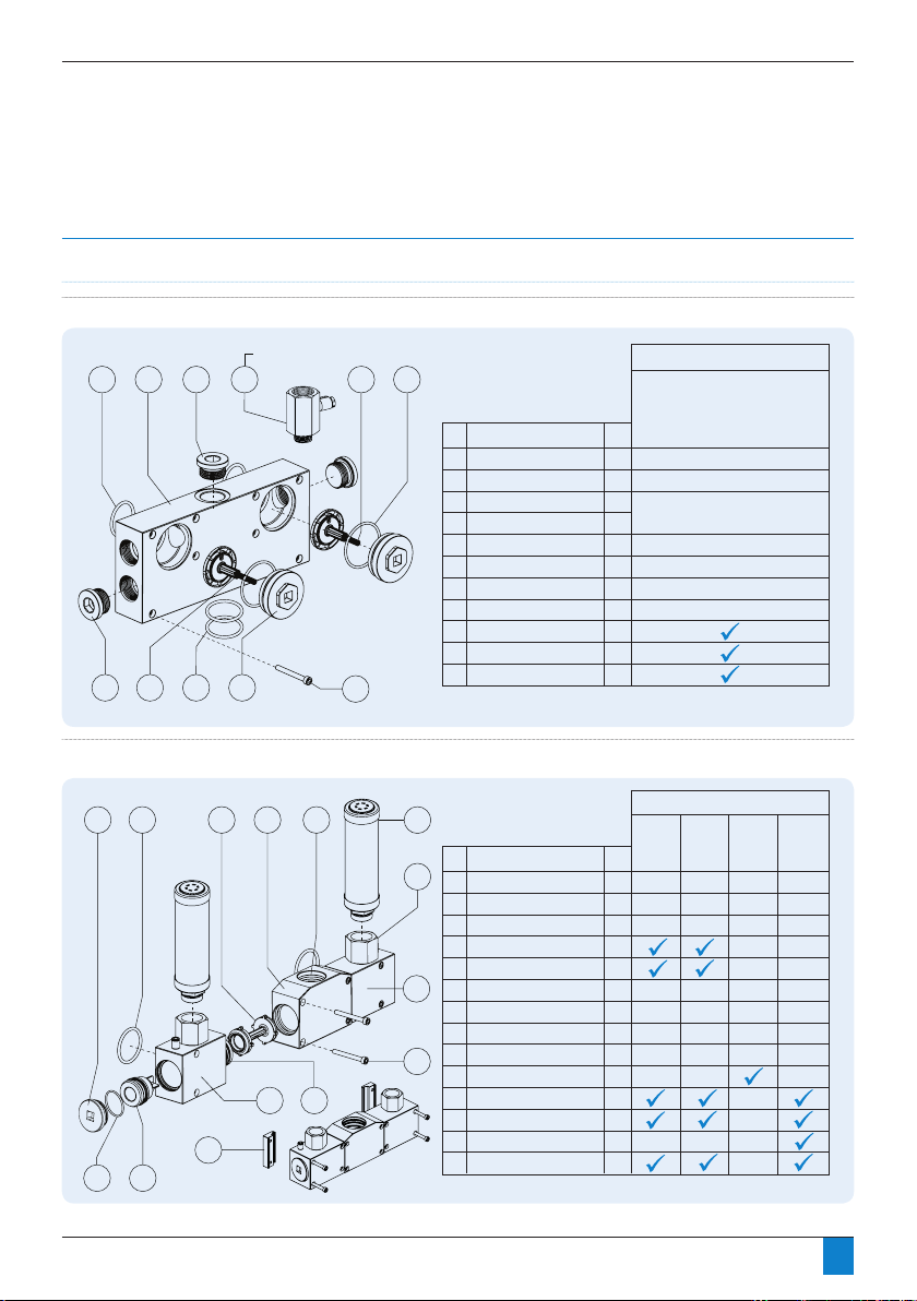
Section 10: Component Parts
Component parts
Fig 10.1 To p manifold assembly
P
Section 10: Component Parts
Component parts
Fig 10.1 To p manifold assembly
P
Section 10: Component Parts
Fig 10.2 Bottom manifold assembly
19
7
4
3
11
6
8
10
5 2
11
2
2
2
2
1
8
1
2
2
2
Itm QtyDescription
2
3
4
5
6
7
8
9
10
Inlet / outlet manifold
Purge valve service plug
Purge control valve
Valve control spring
See figure 10.6
Inlet/outlet blanking plug
Hyg port blanking plug
Manifold fixing bolts
Hygrometer sample block*
* Duplex Only
DMC Only
Manifold connection O-ring
Valve service plug O-ring
11 Down tube O-ring
Included in Service / Accessory Kit
Master Seal
Duplex or
Simplex
Component parts
PD0046 - PD0360
Fig 10.1 Top manifold assembly
DMC Only
6
19
8
Included in Service / Accessory Kit
10
4
5 2
Fig 10.2 Bottom manifold assembly
6 11
3
11
4 3
2 12
9
5
14
7
13
Itm QtyDescription
11
Inlet / outlet manifold
2
Purge valve service plug
3
Purge control valve
4
Valve control spring
5
Inlet/outlet blanking plug
6
Hyg port blanking plug
7
Manifold fixing bolts
8
Hygrometer sample block*
9
Manifold connection O-ring
10
Valve service plug O-ring
11 Down tube O-ring
10
Itm QtyDescription
7
1
RH exhaust manifold
2
LH exhaust manifold
3
Centre shuttle manifold
4
Control shuttle
5
Exhaust control valve
1
6
Valve service plug
7
Silencer adapter
8
Manifold fixing bolt*
9
Duplex fixing clip
8
10
Silencer
Manifold connection O-ring
11
Exhaust manifold O-ring
12
Down tube O-ring
13
14 Valve Service Plug O-ring
Duplex
2
2
2
2
1
8
1
2
2
2
Included in Service / Accessory Kit
1
1
1
1
2
2
2
8/12
2
2
2
4
2
2
Master Seal
See figure 10.6
Valve
Service
Shuttle
Service
* 8 for Simplex / 12 for Duplex
Duplex or
Simplex
Silencer
* Duplex Only
Master
Seal
46
Page 47

Section 10: Component Parts
0 0 0
Section 10: Component Parts
Fig 10.3 To we r assembly (Simplex)
PD0046 - PD0180
Fig 10.3 Tower assembly (Simplex)
Included in Service / Accessory Kit
78
ItmQtyDescription
Tower extrusion
2
9
10
4
1
Extrusion tower plug
2
Desiccant cartridge*
3
4
Cartridge pressure spring
5
Support circlip
6
Floor mounting bracket
7
Trim caps
8
Controller reset magnet
Service cap outer O-ring
9
10
Service cap inner O-ring
3
Desiccant
Cartridge
1
1
2/4
1
2
2
2
2
4
4
* Quantity varies per dryer model
Master
Seal
1
5
6
47
Page 48

Section 10: Component Parts
0
Section 10: Component Parts
Fig 10.4 To we r assembly (Duplex)
PD0046 - PD0180
Fig 10.4 Tower assembly (Duplex)
10
8
Included in Service / Accessory Kit
3
11
ItmQtyDescription
1
12
5
4
2
1
Tower extrusion (Front)
Tower extrusion (Rear)
2
Extrusion tower plug
3
4
Desiccant cartridge
5
Cartridge pressure spring
Support circlip
6
Floor mounting bracket
7
Trim caps
8
9
Clamp assembly
Controller reset magnet
10
11
Service cap outer O-ring
Service cap inner O-ring
12
13
Extrusion O-ring
Desiccant
Cartridge
1
1
8
8
8
4
2
4
4
1
8
8
4
Master
Seal
13
9
6
7
48
Page 49

0
Section 10: Component Parts
Fig 10.5 Controller assembl ies
2
1
1
1
2
3
ItmQtyDescription
Solenoid control valves*
LED controller
DMC controller
* Includes installed tube fittings
** Specify which controller model and/or voltage when ordering
Included in Service /Accessory Kit
Valve Service
Controller**
Solenoid
1
2
3
1
Section 10: Component Parts
0
Section 10: Component Parts
Fig 10.5 Controller assembl ies
Fig 10.6 Purge valve assembly
2
1
1
1
2
3
ItmQtyDescription
Solenoid control valves*
LED controller
DMC controller
* Includes installed tube fittings
** Specify which controller model and/or voltage when ordering
Included in Service /Accessory Kit
Valve Service
Controller**
Solenoid
1
1
1
1
1
1
1
1
1
1
1
1
1
1/2/3
1
2
3
4
5
6
7
8
9
10
11
12
13
14
ItmQtyDescription
Purge valve body
Orifice disc (01)
Orifice disc (02)
Orifice disc (03)
Orifice disc (04)
Sealing gasket (1 Hole)
Sealing gasket (2 Hole)
Sealing gasket (3 Hole)
Valve stem O-ring
Valve stem (1 Hole)
Valve stem (2 Hole)
Valve stem (3 Hole)
M4 screw
Valve control spring
Included in Service / Accessory Kit
Purge Valve Body (1 Hole)
Purge Valve Body (2 Hole)
Purge Valve Body (3 Hole)
Purge Orifice Disc
1
2
3
1
1
2
3
4
5
13 14
6 7 8 129
1110
PD0046 - PD0180
Fig 10.5 Controller assemblies
Fig 10.6 Purge valve assembly
49
Page 50

Section 11: Troubleshooting
Troubleshooting
General troubleshooting
Before specic identication of any fault is looked for, the following general points must be veried:
• Has the unit been damaged externally or are any parts missing?
• Is power being supplied to the unit?
• Was start-up carried out in accordance with the instructions in this manual?
• Are all external valves correctly set for operation?
• Do the operational conditions meet those specied at time of ordering and used for product selection?
• Did the dryer operate normally for a period of time before the problem occured?
Before calling for service assistance, please obtain dryer model
and serial number from dryer specification label.
Troubleshooting: General
Problem
Poor dewpoint
Incorrect dryer operation,
won’t switch towers
Incorrect dryer operation,
won’t depressurise towers
Excessive or loud purge,
or purge on only one tower
Possible Cause Action
Liquid water at dryer inlet Check pre-filtration and drains
Excessive flow Check actual flow against maximum specified
Low inlet pressure Check against specification
High inlet temperature Check against specification
Incorrect purge orice size Check against specication and recongure
Silencer blocked or damaged Replace silencer
Air leaks Tighten joints or fit new seals
Desiccant life exceeded Replace desiccant cartridges
Desiccant contaminated
EM is active when air is owing
through dryer
Power to dryer off while air is owing through
dryer
Jammed shuttle valves Clean or replace shuttles
Faulted electrical components See electrical operation troubleshooting section
Jammed purge exhaust shuttle Clean or replace exhaust shuttles and solenoid valves
Blocked and/or damaged silencer Replace silencer
Jammed main control shuttle valve Clean or replace shuttles
Jammed purge exhaust shuttle Clean or replace exhaust shuttles
Faulty solenoid valve Clean or replace solenoid valve
Not utilising Energy Management feature Refer to Energy Management instructions (Section 7)
Blocked and/or damaged silencer Replace silencer and check desiccant cartridges
Damaged purge valve(s) Replace purge valve bodies
Incorrect purge orifice size Double check and select correct size
Check inlet lter and drains,
replace cartridges
Check EM wiring, DMC and/or control method used
Ensure that power is on whenever air is owing
through dryer
50
Page 51

Section 11: Troubleshooting
Troubleshooting: Electrical
Problem
No dryer function No power supply Check supply
Dryer does not activate external
alarm
when display panel indicates alarm
condition
Possible Cause Action
Power connected to wrong controller input Check connections with specifications
Faulty controller Replace controller
Shorted or incorrect device wiring Correct external wiring
External power not supplied Add external power source per specifications
Faulty external indication device Repair or replace device
Faulty controller Replace controller
listed in
Section 5
given in Section 5
Troubleshooting: Energy Management
Problem
Dryer does not enter Energy
Management when switching device is
activated and/or Dryer does not enter
Energy Management when EM contacts
are opened.
Possible Cause Action
Shorted or incorrect device wiring Remove external wiring from the dryer’s EM
Faulty switching device Consult device manufacturer
Faulty controller output Replace controller
contacts:
• On LED controllers, dryer should enter
EM mode.
• On DMC controllers, place jumper
between pins 1 and 2 of EM male
connector. Dryer should enter EM
mode.
• If dryer enters EM mode, correct
external wiring problem
• If dryer does not enter EM mode,
replace controller
Troubleshooting: Dewpoint control (DMC Controller only)
Problem
Dryer does not enter dewpoint mode Hygrometer Din plug not connected correctly
Dryer controller displaying hygrometer
out of range
Possible Cause Action
to hygrometer
Demand is too high, dryer undersized Check against specification
Hygrometer not reading accurately / fouled Verify hygrometer calibration
Hygrometer failed (electrically) Replace hygrometer
Hygrometer is reading an outlet dewpoint of
either +20°C or -100°C which is the
maximum limits of the hygrometer
Check Din plug is tightly connected to
hygrometer with the Din plug
Check hygrometer is functioning correctly
and not damaged
51
Page 52

RESET
RESET
RESET
RESET
RESET
RESET
RESET
RESET
RESET
RESET
RESET
RESET
RESET
RESET
RESET
RESET
RESET
RESET
RESET
RESET
RESET
RESET
RESET
RESET
RESET
RESET
RESET
RESET
RESET
RESET
RESET
RESET
RESET
RESET
RESET
Section 11: Troubleshooting
Troubleshooting - LED Display Status Identication
LED Identification Function Indication Remark
N/A Power Off Power supply disconnected
Z Power On
X Left tower ‘Online’ Left tower drying
Y Right tower ‘Online’ Right tower drying
X & Y Both towers ‘Online’
RESET
RESET
RESET
RESET
One tower drying, the other tower
RESET
repressurising
X Left solenoid failure Clean or replace solenoid
RESET
52
Page 53

Section 11: Troubleshooting
RESET
RESET
RESET
RESET
RESET
RESET
RESET
RESET
RESET
RESET
LED Number Function Indication Remark
Y Right solenoid failure Clean or replace solenoid
1 Service warning 11500 hours continuous operation
RESET
RESET
2 Service alarm 12000 hours continuous operation
1 & 2 Controller reset
N/A Power Failure Replace controller
RESET
Activated when the reset magnet
RESET
RESET
is applied
53
Page 54

Section 11: Troubleshooting
Function Indication Remark
Full DMC message layout
Line message 1
Line message 2
Line message 3
Line message 4
Dryer functioning in standard
running mode
Dryer functioning in standard
running mode (service due)
Dryer functioning in standard
running mode (service overdue)
Energy management mode
active
Energy management mode
active (service due)
Line message 1
Line message 2
Line message 3
Line message 4
Line message 1
Line message 2
Line message 3
Line message 4
Line message 1
Line message 2
Line message 3
Line message 4
Line message 1
Line message 2
Line message 3
Line message 4
Line message 1
Line message 2
Line message 3
Line message 4
STANDARD RUNNING MODE
-
HOURS RUN XXXXX
SERVICE HISTORY # XX
STANDARD RUNNING MODE
-
SERVICE DUE (XXX HOURS)
SERVICE HISTORY # XX
STANDARD RUNNING MODE
-
SERVICE OVERDUE
SERVICE HISTORY # XX
ENERGY MANAGEMENT MODE
-
HOURS RUN XXXXX
SERVICE HISTORY # XX
ENERGY MANAGEMENT MODE
-
SERVICE DUE (XXX HOURS)
SERVICE HISTORY # XX
(500 hour countdown until 12000 hours
(12000 hours continuous operation)
(500 hour countdown until 12000 hours
Service due
continuous operation)
Service overdue
Service due
continuous operation)
Energy management mode
active (service overdue)
Line message 1
Line message 2
Line message 3
Line message 4
ENERGY MANAGEMENT MODE
-
SERVICE OVERDUE
SERVICE HISTORY # XX
Service overdue
(12000 hours continuous operation)
54
Page 55

Section 11: Troubleshooting
Function Indication Remark
Dewpoint mode active (-20)
Dewpoint mode active (-40)
Dewpoint mode active (-74)
or
or
Line message 1
Line message 2
Line message 3
Line message 4
DEWPOINT MODE (-20) (-40) (-74)
DRYER DEWPOINT -XXX PDP
HOURS RUN XXXXX
SERVICE HISTORY # XX
Dewpoint mode active but dryer in standard
cycle mode
Dewpoint hold active (-20)
Dewpoint hold active (-40)
Dewpoint hold active (-74)
Dewpoint mode active (-20) –
Dewpoint mode active (-40) –
Dewpoint mode active (-74) –
Dewpoint mode active (-20) –
Dewpoint mode active (-40) –
Dewpoint mode active (-74) –
Dewpoint hold active (-20) –
Dewpoint hold active (-40) –
Dewpoint hold active (-74) –
Dewpoint hold active (-20) –
Dewpoint hold active (-40) –
Dewpoint hold active (-74) –
or
or
service due
or
service due
or
service due
service overdue
or
service overdue
or
service overdue
service due
or
service due
or
service due
service overdue
or
service overdue
or
service overdue
Hygrometer out of range
Line message 1
Line message 2
Line message 3
Line message 4
Line message 1
Line message 2
Line message 3
Line message 4
Line message 1
Line message 2
Line message 3
Line message 4
Line message 1
Line message 2
Line message 3
Line message 4
Line message 1
Line message 2
Line message 3
Line message 4
Line message 1
Line message 2
Line message 3
Line message 4
DEWPOINT HOLD (-20) (-40) (-74)
DRYER DEWPOINT -XXX PDP
HOURS RUN XXXXX
SERVICE HISTORY # XX
DEWPOINT MODE (-20) (-40) (-74)
DRYER DEWPOINT -XXX PDP
SERVICE DUE (XXX HOURS)
SERVICE HISTORY # XX
DEWPOINT MODE (-20) (-40) (-74)
DRYER DEWPOINT -XXX PDP
SERVICE OVERDUE
SERVICE HISTORY # XX
DEWPOINT HOLD (-20) (-40) (-74)
DRYER DEWPOINT -XXX PDP
SERVICE DUE (XXX HOURS)
SERVICE HISTORY # XX
DEWPOINT HOLD (-20) (-40) (-74)
DRYER DEWPOINT -XXX PDP
SERVICE OVERDUE
SERVICE HISTORY # XX
XXXXXXXXXXXXXXX
XXXXXXXXXXXXXXXXXXXXX
XXXXXXXXXXXXXXXXXXXXX
HYGROMETER OUT OF RANGE
Dewpoint hold active purge flow has been
Dewpoint mode active but dryer in standard
cycle mode (500 hour countdown until 12000
Dewpoint mode active, dryer in standard cycle
mode (12000 hours continuous operation)
Dewpoint hold active, purge flow has been
isolated – 500 hour countdown until 12000
Dewpoint hold active, purge flow has been
isolated – 12000 hours continuous operation
Check din plug and wiring connections
between hygrometer and Dryer controller
isolated
hours continuous operation)
hours continuous operation
55
Page 56

Section 12: Warranty
Warranties and liabilities
Claims for warranty and liability concerning personal injury or
material damage are excluded if they resulted due to one or
more of the following factors:
• Inappropriate use
• Inappropriate application of the dryer.
• Technically incorrect installation, start-up operation or
maintenance of the dryer.
• Operation of a known damaged dryer.
• Failure to observe the information given in this manual
concerning all life phases of the dryer.
• Undertaking constructional or operational modications to
the dryer without prior agreement with Walker Filtration.
• Inadequate monitoring and replacement of components
of the dryer that are subject to wear.
• Improper completion of repairs.
• Use of non-original or non-approved parts for service or
maintenance.
The warranty of this product could become void if the
correct filtration is not installed upstream of the dryer.
It is recommended that the inlet filtration upstream of
the dryer consists of a WS, X1 then XA. However, it is
essential that a WS followed by a XA is used
Important Note
Industrial Compressed Air Desiccant Dryers
The Walker Filtration Ltd desiccant dryer range is designed for,
warrantied and intended for use in xed industrial compressed
air applications only.
Use on non-xed installations such as :
Such additional undertakings are the responsibility of
the package or system builder, installer or end user.
• marine (e.g. offshore, shipboard)
• transportable (e.g. portable air treatment units)
• non-xed (e.g. rolling stock, railway etc)
are not strictly prohibited, however use in such applications is
not recommended nor endorsed as additional design features,
function testing, certication (both mechanical and electrical)
and validation may be required to satisfy relevant end user
application specic specications and/or mandatory and
non-mandatory local, national or international standards
and legislation.
56
Page 57

Section 13: Declaration of Conformity
Declaration of Conformity
2014/30/EU, 2014/35/EU, 2014/68/EU (97/23/EC)
Name of Manufacturer
Address of Manufacturer
Description of Product
Designation of Product
Standards Used
Harmonised Standards* applied where
available — with alternatives specified where
harmonised standards do not exist.
Notified Body
Pressure Equipment Directive (PED) Only
Conformity Assessment Module
Pressure Equipment Directive (PED) Only
Quality Assurance System
Year of Manufacture
Name of Authorised Representative
Position of Authorised Representative
Walker Filtration Ltd.
Birtley Road, Washington, Tyne & Wear, NE38 9DA, England.
PRODRY Compressed Air Desiccant Dryers
PD0046, PD0056, PD0075, PD0090, PD0110, PD0150, PD0180, PD0220, PD0300, PD0360
LVD: 2014/35/EU EN 61010-1:2010*
EMC: 2014/30/EU EN 61000-6-2:2005+AC:2005*
PED: 97/23/EC
PED: 2014/68/EU (From 19-07-2016)
Lloyds Register EMEA
Notied Body No.0038
71 Fenchurch Street, London, EC3M 4BS, England
PD0046-PD0180: Cat II Module D1 [COV0310124/1]
PD0220-PD0360: Cat III Module B1 [COV1611049/1]**+ D [COV1112690/1]
**Module B1 certicate issued by conformity assessment body under directive 97/23/EC and
remains valid under the new directive as dened in 2014/68/EU Article 48.
ISO 9001:2008
Certicate Number LRQ 0930553
Lloyds Register Quality Assurance Ltd (LRQA)
1 Trinity Park, Bickenhill Lane, Birmingham, B37 7ES, United Kingdom
Refer to product marking
Simon Wise
CTO (Chief Technical Ofcer)
This declaration of conformity is issued under the sole responsibility of the manufacturer. I
declare on behalf of Walker Filtration Ltd (the manufacturer) and as authorised representative,
that the above stated products full the requirements of the new approach directives
EN 61000-6-3:2007+A1:2011+AC:2012*
Generally in accordance with
ASME VIII Division 1
Rules for Construction of Pressure Vessels
July 2016
57
Page 58

3770B Laird Road, Unit 2
Mississauga, Ontario L5L 0A7
Tel: 800-951-0777 Fax: 905-820-3490
www.cagpurification.com
 Loading...