

P.1
W70FENSMD
Copyright
©
2020
, by Walker Edison Furniture Co., LLC. All rights reserved.
Please visit our website for the most current instructions, assembly tips, report damage,
TM
Walker Edison
or request parts. www.walkeredison.com
Revised 27/07/2020(C)
®
General Assembly Guidelines
Copyright
©
2020
, by Walker Edison Furniture Co., LLC. All rights reserved.
P.2
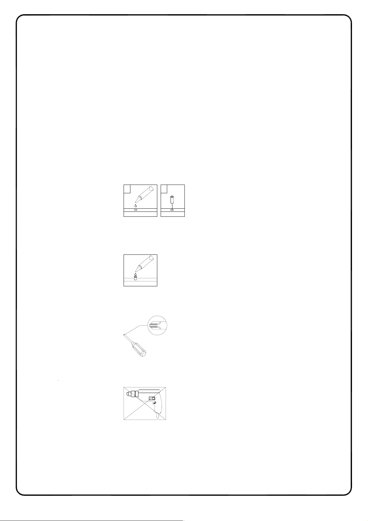
I. Ensure that all parts and hardware are available before beginning assembly.
II. Follow each step carefully to ensure the proper assembly of this product.
III. Two people are recommended for ease in the assembly of this product.
IV. The three main types of hardware used to assemble this product are: wood
dowels, screws and bolts.
V. The provided glue is to secure wood dowels in place. When first inserting dowels,
locate the appropriate hole for the dowel, place a small amount of glue in the hole
and insert the dowel. Wipe away excess glue immediately.
21
In future assembly steps when dowels are necessary to attach assembly parts
together, place a small amount of glue on the end of the dowel before attaching
parts together. Wipe away excess glue immediately.
VI. A Phillips head screwdriver is required for the assembly of this product .
VII. Power tools should not be used to assemble this product.
VIII. Drill may be needed for securing product to wall.
P.3
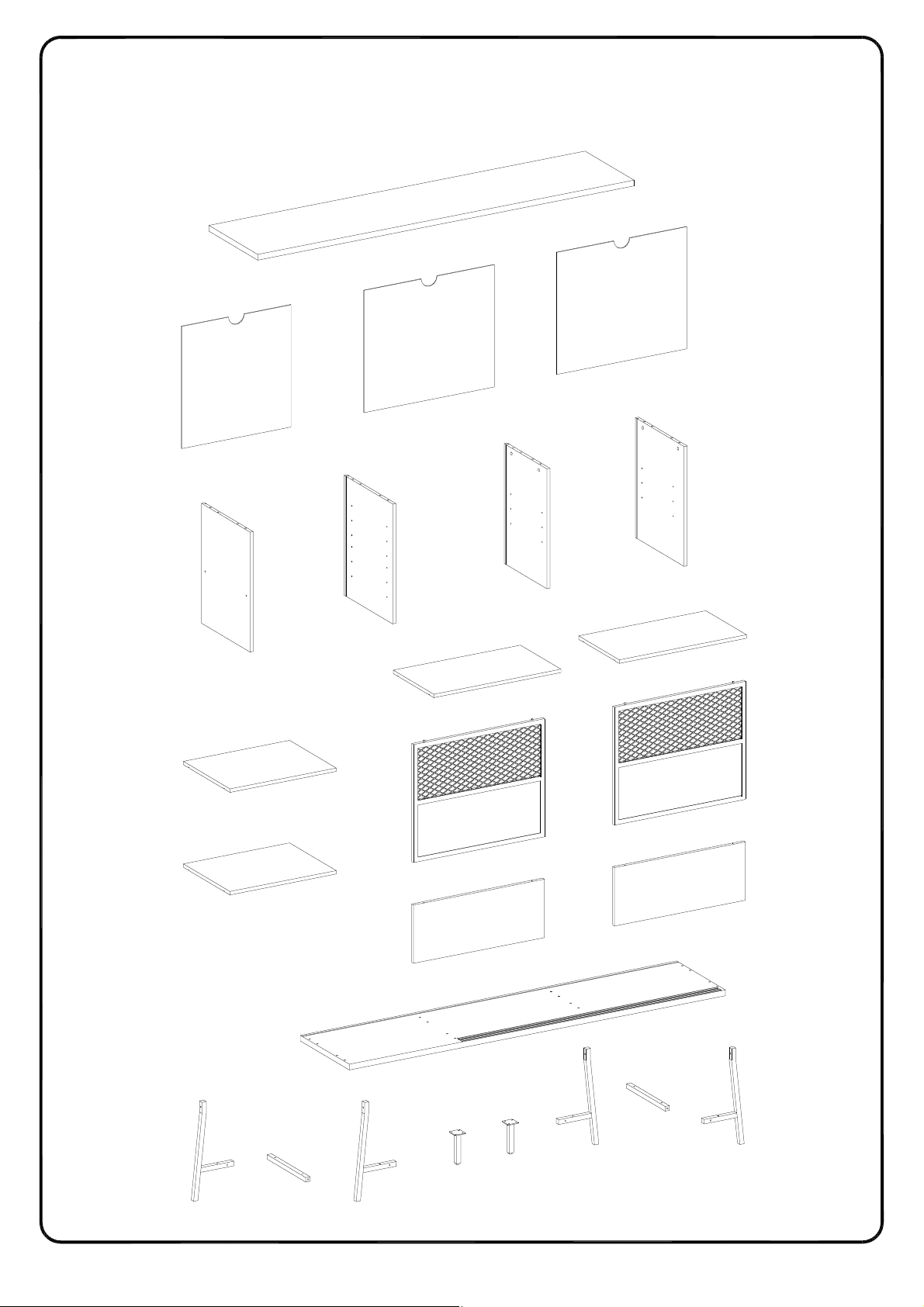
Parts List
Copyright
©
2020
, by Walker Edison Furniture Co., LLC. All rights reserved.
1
4
4
3
8
7
6
5
10
10
9
11
11
9
12
12
13
14
13
15
15
2
13
14
13
P.4
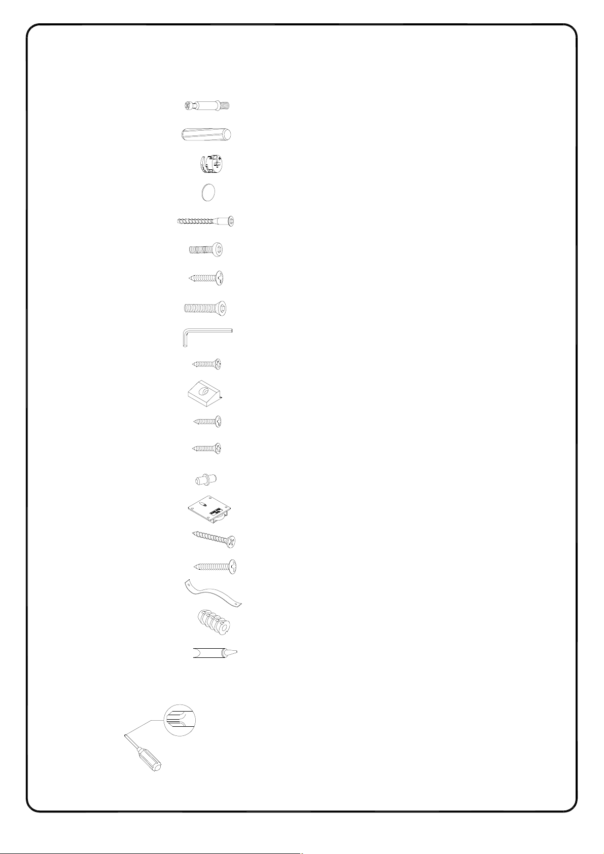
Hardware List
Copyright
©
2020
, by Walker Edison Furniture Co., LLC. All rights reserved.
A
B
G 10 pcs
H 4 pcs
J 1 pc
Ø6x35mm Cam bolt
Ø8x30mm Wooden dowel
Ø15x11mm Cam lockC 8 pcs
Ø30mm StickerD 8 pcs
Ø6x50mm ScrewE 8 pcs
Ø1/4"x30mm BoltF 12 pcs
Ø4x12mm Screw
Ø1/4"x30mm Bolt
M 4 Hex key
Ø3x17mm ScrewK 12 pcs
Plastic wedgeL 12 pcs
8 pcs
16 pcs
M 4 pcs
N 16 pcs
Q
R
S
T
U
V
Ø3x15mm Screw
Ø3x12mm Screw
Shelf support pinP 16 pcs
Pulley 4 pcs
Ø4x38mm Screw
Ø4x30mm Screw
Plastic strap
Nut
Glue tube
4 pcs
2 pcs
2 pcs
2 pcs
1 pc
Philips head screwdriver required for assembly
The hardware quantities listed above are required for proper assembly.
Some extra hardware may also have been included.
(not included)
P.5
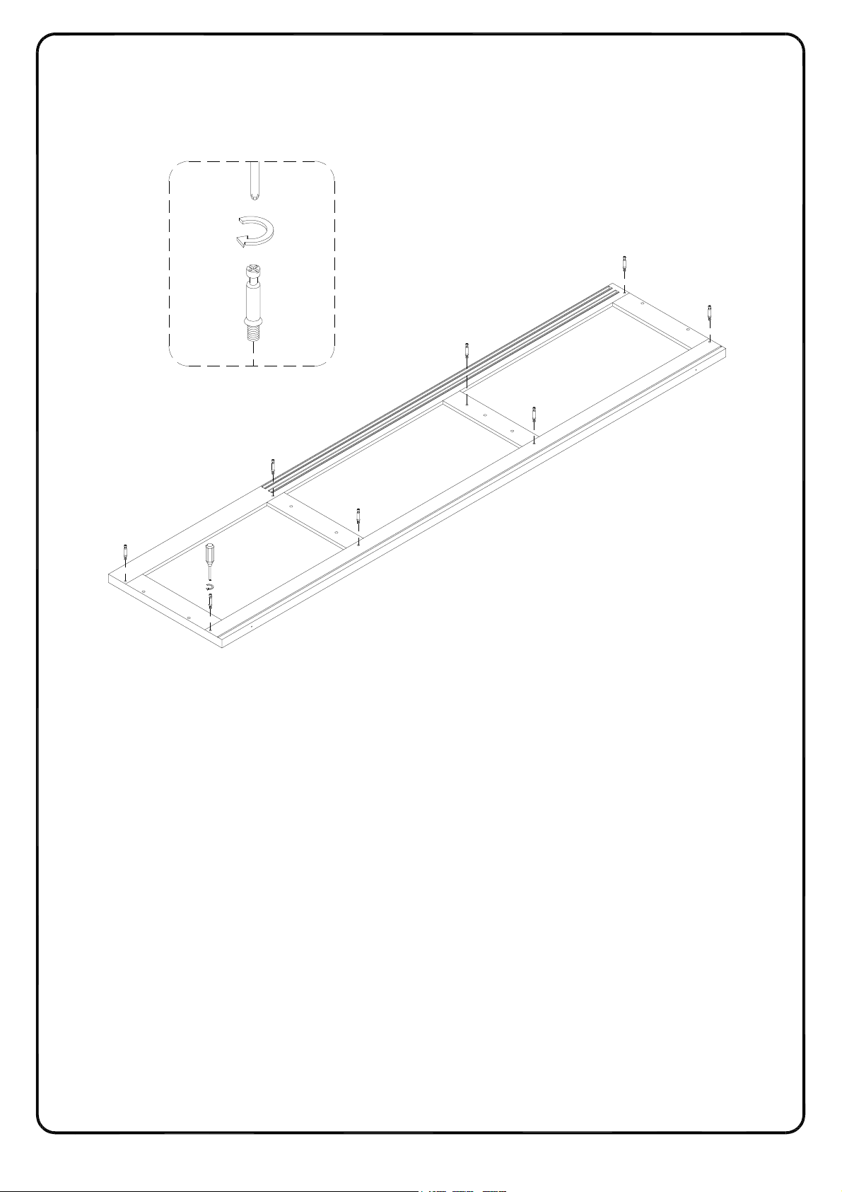
Step 1
Copyright
©
2020
, by Walker Edison Furniture Co., LLC. All rights reserved.
Secure cam bolt (A) into part (1) with Philips head screwdriver as per diagram.
A
1
P.6
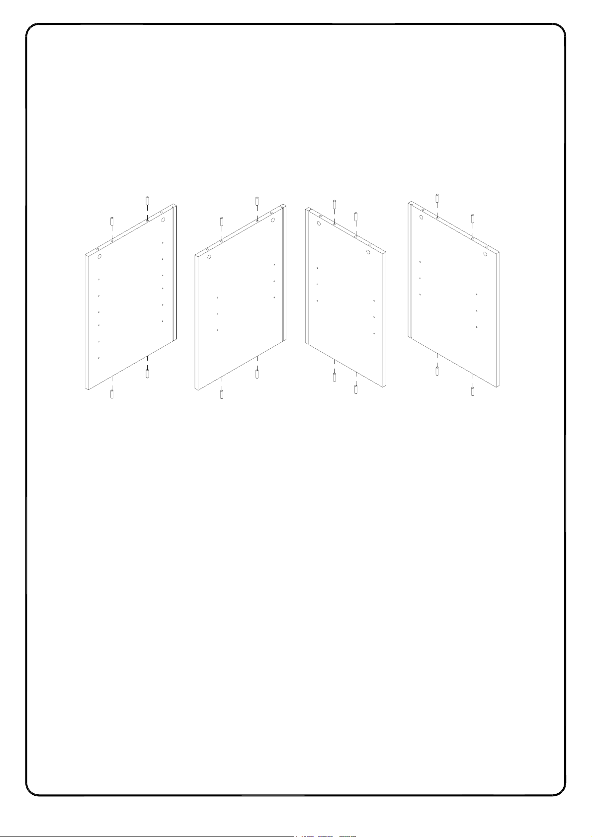
Step 2
Copyright
©
2020
, by Walker Edison Furniture Co., LLC. All rights reserved.
Insert wooden dowel (B) into parts (5,6,7,8) as per diagram.
B
B
5
B
B
B
B
B
B
6
B
7
B
B
B
8
B
B
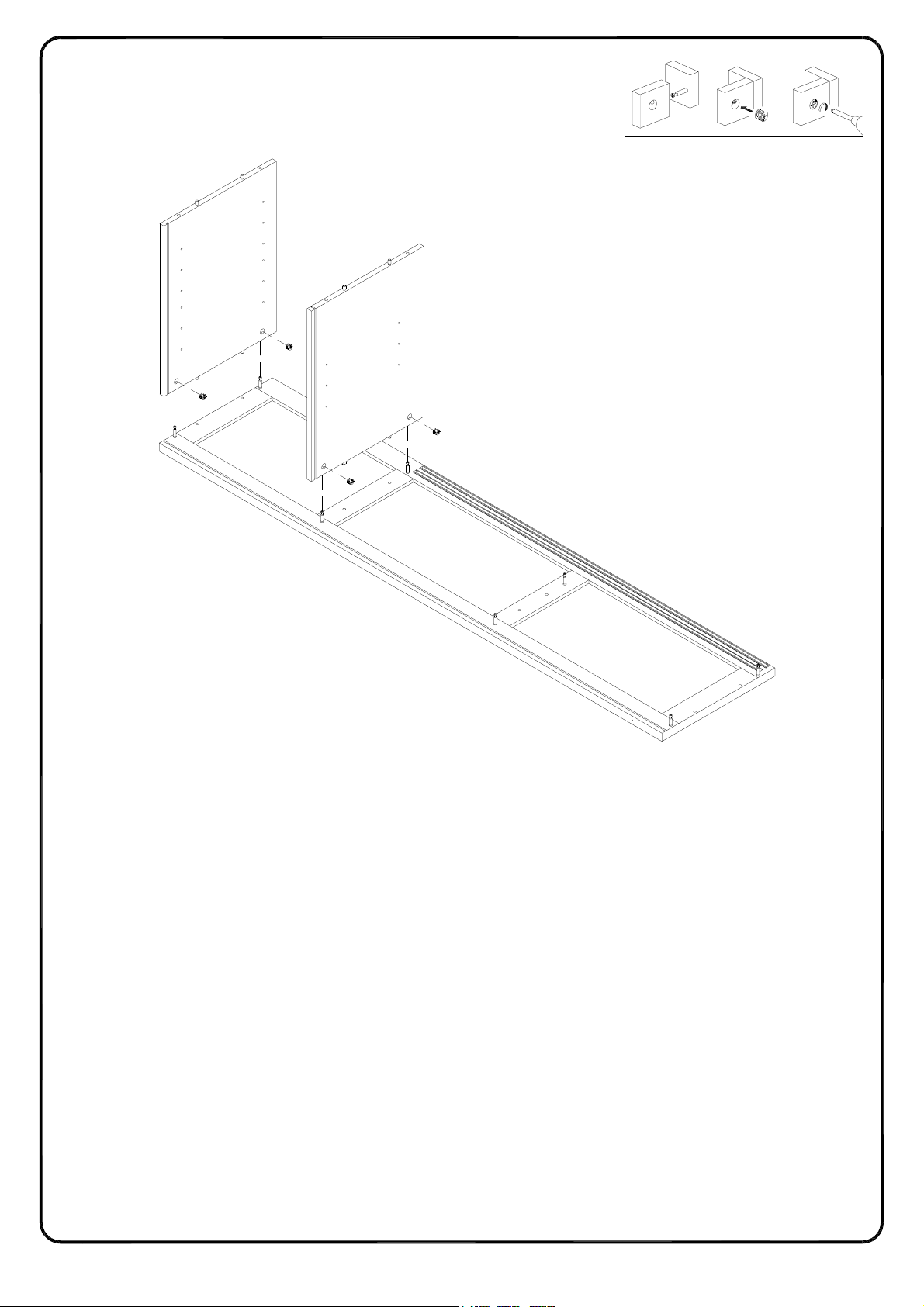
Step 3
P.7
Copyright
©
2020
, by Walker Edison Furniture Co., LLC. All rights reserved.
Using Cam lock(C) secure parts (5,6) to part (1) with Philips head screwdriver as per diagram.
21 3
5
C
C
6
C
C
1
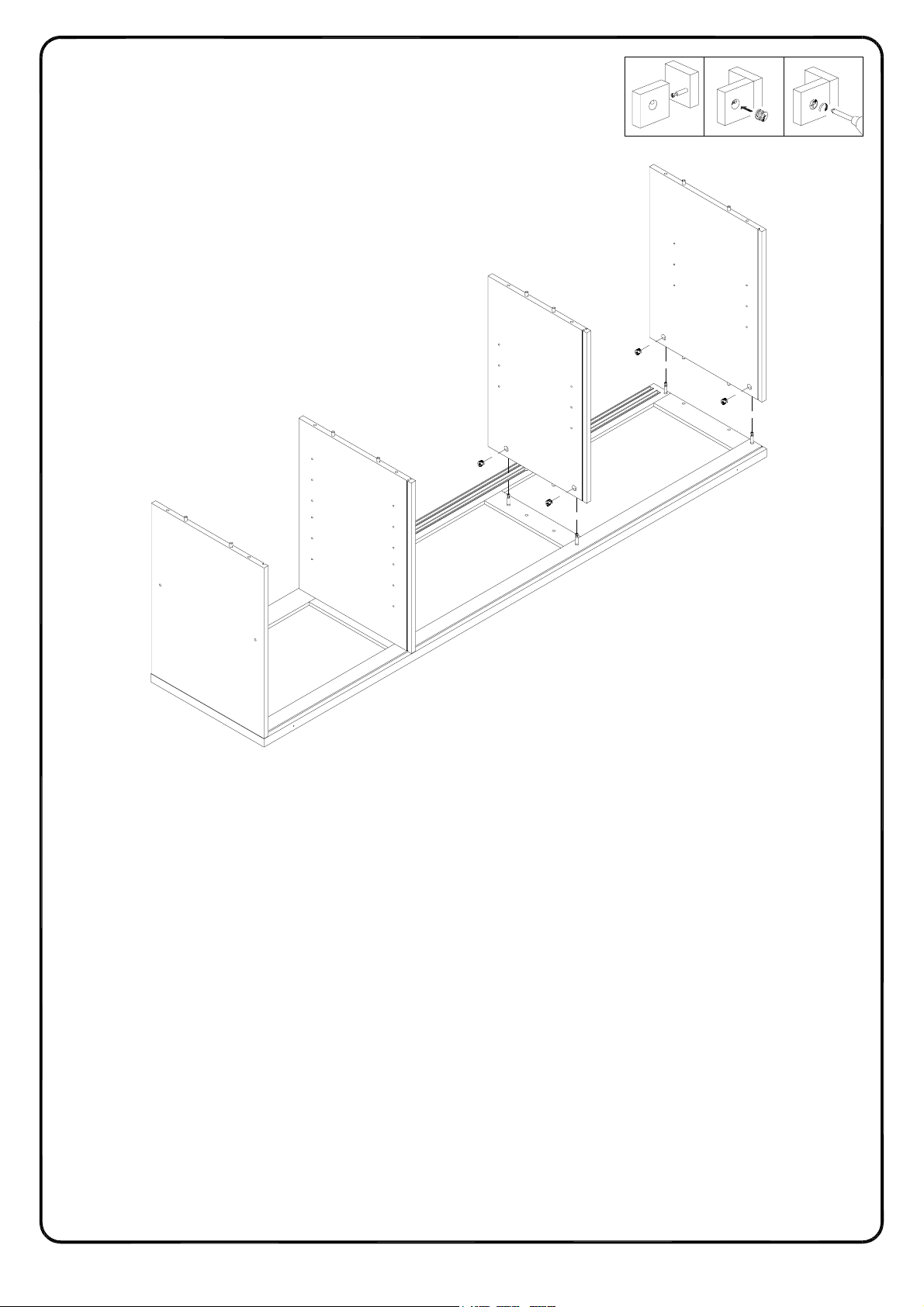
Step 4
P.8
Copyright
©
2020
, by Walker Edison Furniture Co., LLC. All rights reserved.
Using Cam lock(C) secure parts (7,8) to part (1) with Philips head screwdriver as per diagram.
21 3
8
C
7
C
C
C
1
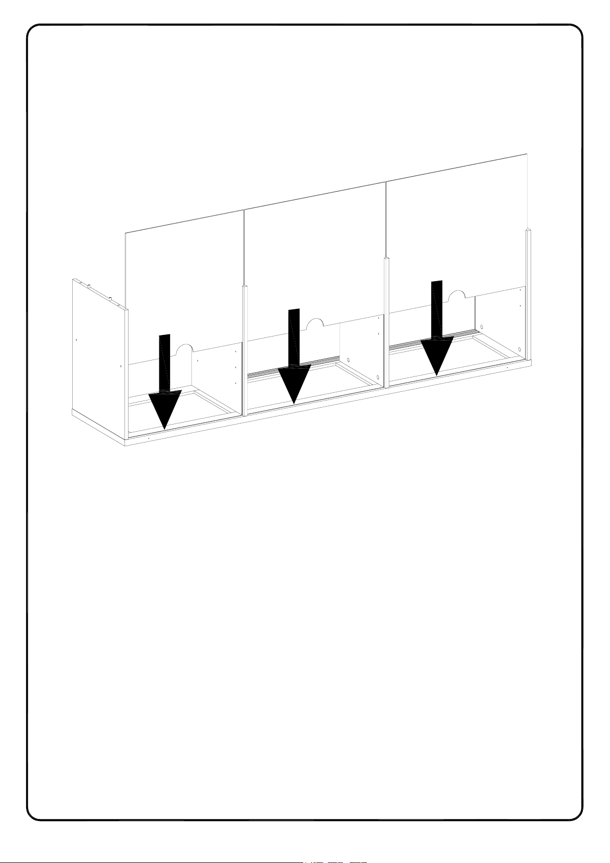
Step 5
P.9
Copyright
©
2020
, by Walker Edison Furniture Co., LLC. All rights reserved.
Put parts (3,4) as per diagram.
4
4
3
8
5
1

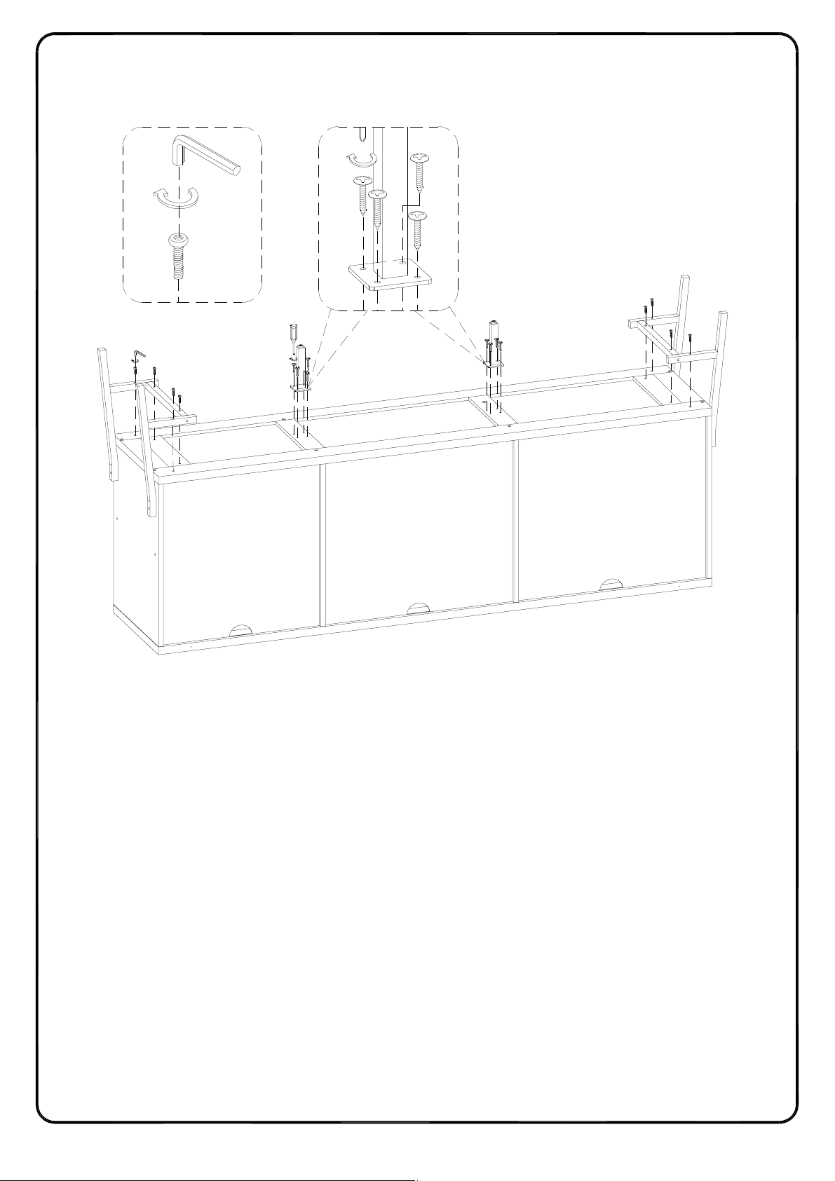
Step 6
P.10
Copyright
©
2020
, by Walker Edison Furniture Co., LLC. All rights reserved.
Using screw (E) attach part (2) into parts (5,6,7,8) with Hex key (J) as per diagram.
J
E
2
8
7
6
5

P.11
Step 7
Copyright
©
2020
, by Walker Edison Furniture Co., LLC. All rights reserved.
Using Bolt (F) attach part (13) to part (14),then using bolt (F) attach part (13) to part (14)
with Hex key (J) as per diagram.
J
14
F
14
13
13
x 2
Copyright
©
2020
, by Walker Edison Furniture Co., LLC. All rights reserved.
P.12
Step 8
Using bolt (F) attach part (13) to part (2) with Hex key (J) ,then using screw (G) attach part (15)
to part (2) with Philips head screwdriver as per diagram.
J
13
13
G
F
15
F
F
14
G
13
F
15
14
2
13
F
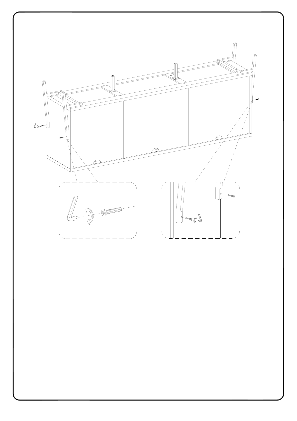
Step 9
P.13
Copyright
©
2020
, by Walker Edison Furniture Co., LLC. All rights reserved.
Using bolt (H) attach part (13) to parts (5,8) with Hex key (J) as per diagram.
13
13
5
H
H
8
13
J
H
J
13
Step 10
P.14
Copyright
©
2020
, by Walker Edison Furniture Co., LLC. All rights reserved.
Using screw (K) secure plastic wedge (L) with Philips head screwdriver as per diagram.
L
K
L

Step 11
P.15
Copyright
©
2020
, by Walker Edison Furniture Co., LLC. All rights reserved.
Place sticker (D) cover the holes as per diagram .
D

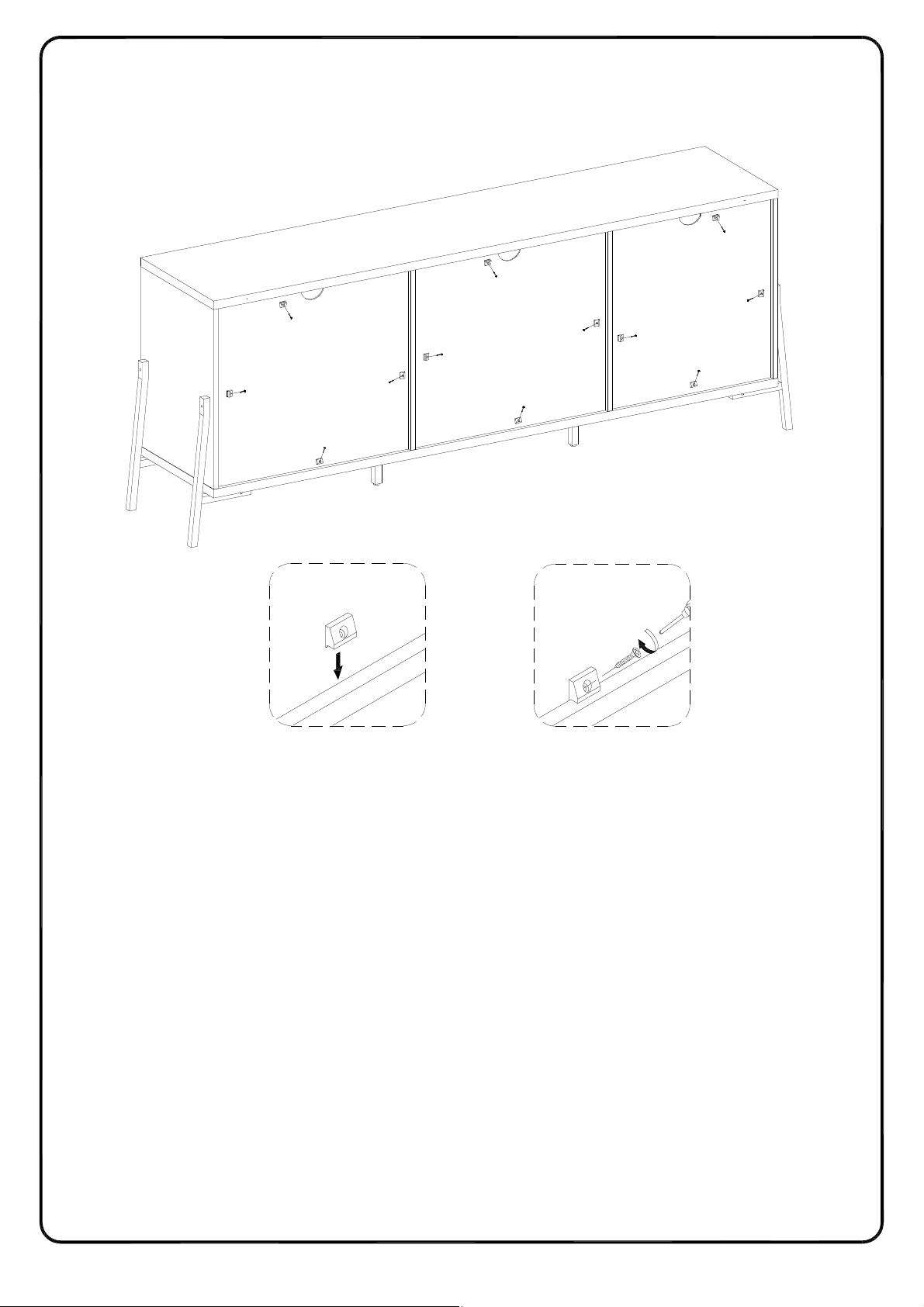
Step 12
P.16
Copyright
©
2020
, by Walker Edison Furniture Co., LLC. All rights reserved.
Place part (12) to part (11) ,then using screws (M,R) secure part (11) to part (12) with Philips head
screwdriver as per diagram.
M
12
12
11
11
R
x 2

Step 13
P.17
Copyright
©
2020
, by Walker Edison Furniture Co., LLC. All rights reserved.
Using screw (N) attach Pulley (Q) to part (12) with Philips head screwdriver as per diagram.
N
N
Q
12
x 2

Step 14
P.18
Copyright
©
2020
, by Walker Edison Furniture Co., LLC. All rights reserved.
Please kindly note that you can adjust the height of the wheels to make the door keeping good fit
by adjusting the screw as per diagram.
Q
12
x 2

Step 15
P.19
Copyright
©
2020
, by Walker Edison Furniture Co., LLC. All rights reserved.
Insert the upper pins of part (11) into the groove of part(1) .Lift up the door in vertical position with
the bottom panel (2) ,lay down the door and keep the wheels matching with the track in bottom
panel as per diagram .
1
1
11
2
Q
2

Step 16
P.20
Copyright
©
2020
, by Walker Edison Furniture Co., LLC. All rights reserved.
Insert the upper pins of part(11) into the groove of part(1) .Lift up the door in vertical position with
the bottom panel (2) ,lay down the door and keep the wheels matching with the track in bottom
panel as per diagram .
1
1
11
2
Q
2

Step 17
P.21
Copyright
©
2020
, by Walker Edison Furniture Co., LLC. All rights reserved.
Slide the doors (11) to the left and right .If necessary , re-assemble the doors for a good fit
and sliding smoothly.
11

Step 18
P.22
Copyright
©
2020
, by Walker Edison Furniture Co., LLC. All rights reserved.
Please kindly note that you can adjust the height of the wheels to make the door keeping good fit
by adjusting the screw as per diagram.
11
Q

Step 19
P.23
Copyright
©
2020
, by Walker Edison Furniture Co., LLC. All rights reserved.
Slide the doors (11) to the left and right .If necessary , re-assemble the doors for a good fit
and sliding smoothly.
11

Step 20
P.24
Copyright
©
2020
, by Walker Edison Furniture Co., LLC. All rights reserved.
Insert shelf support pin (P) into parts (5,6,7) as per diagram. Make sure you place the shelf
support pins (P) in the same level. So the shelf is not titled .Put parts (9,10) into unit as
per diagram. Tilt and rest the adjustable shelves (9,10) onto the shelf support pins .
7
5
P
6
9
9
10
Finished edge
P

Copyright
©
2020
, by Walker Edison Furniture Co., LLC. All rights reserved.
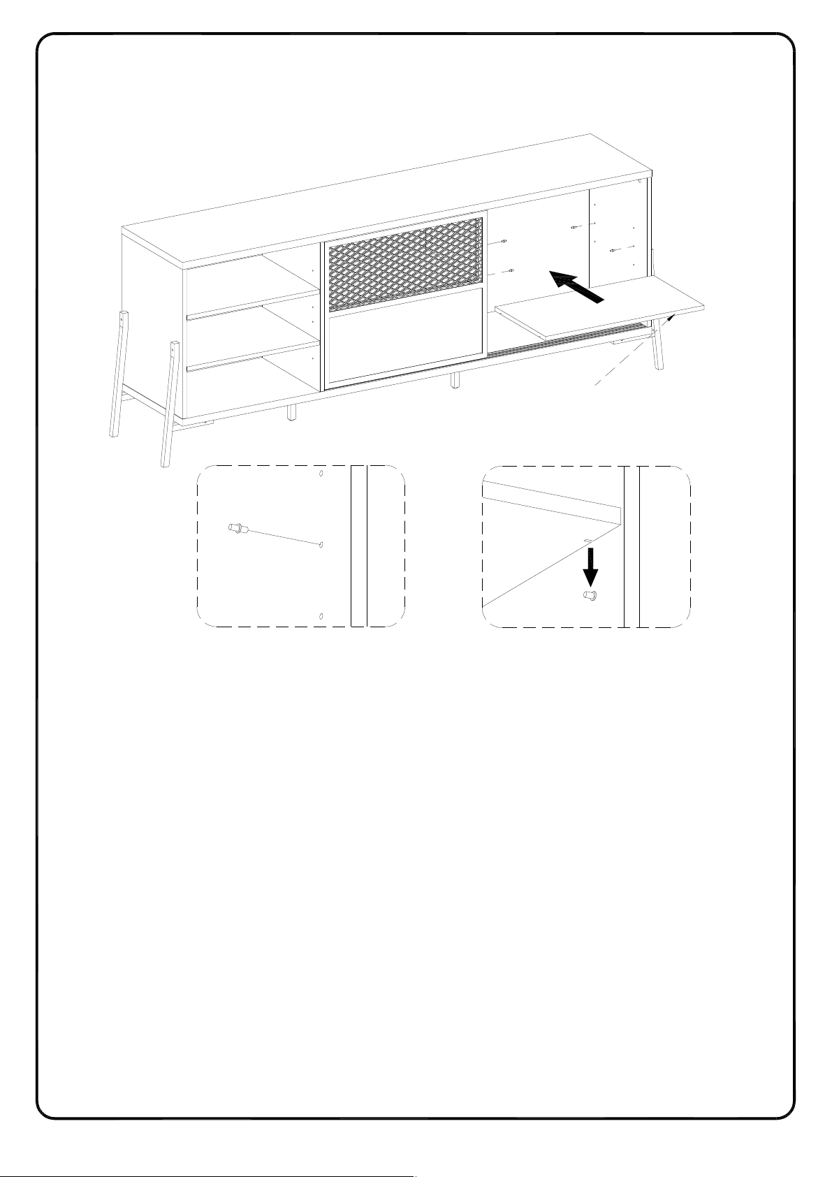
Step 21
P.25
Slide the doors (11) to the left and right as per diagram.
11
Copyright
©
2020
, by Walker Edison Furniture Co., LLC. All rights reserved.
Step 22
P.26
Insert shelf support pin (P) into parts (7,8) as per diagram. Make sure you place the shelf
support pins (P) in the same level. So the shelf is not titled .Put part (10) into unit as
per diagram. Tilt and rest the adjustable shelf (10) onto the shelf support pins .
8
7
Finished edge
P
P
10

Copyright
©
2020
, by Walker Edison Furniture Co., LLC. All rights reserved.
Step 23
P.27
Position the assembled unit at the desired location ,if necessary adjust the floor leveler at the
bottom of the support leg to level the unit .
P.28
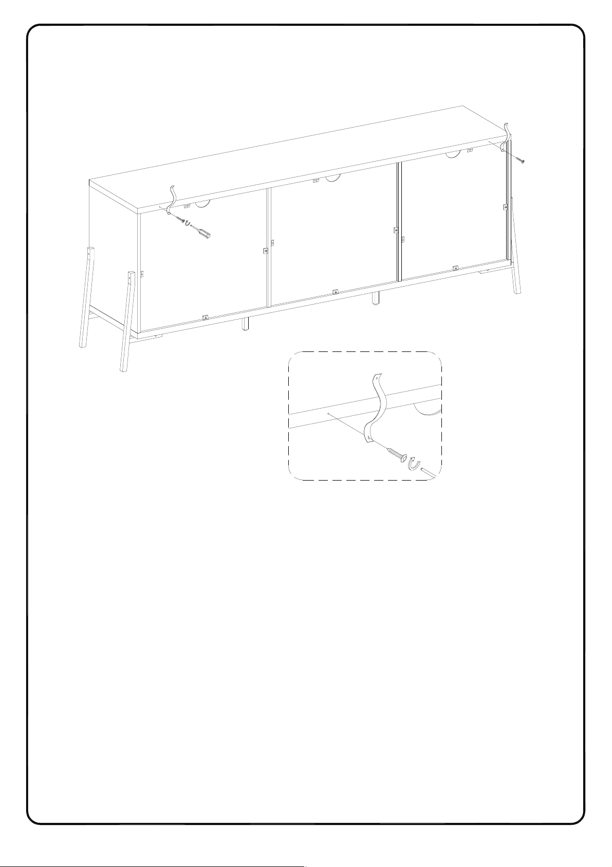
Step 24
Copyright
©
2020
, by Walker Edison Furniture Co., LLC. All rights reserved.
Using screw (G) attach Velcro strap (T) into part (1) with Philips head screwdriver as per diagram.
1
T
G

21 3
Copyright
©
2020
, by Walker Edison Furniture Co., LLC. All rights reserved.
P.29
Using screw (S) attach Velcro strap (T) into Nut (U) to wall with Philips head screwdriver
as per diagram.
Step 25
WARNING
Serious or fatal injuries can occur from furniture tipping over. To prevent the furniture from tipping over we recommend
that it is permanently fixed to the wall. Wall anchor and hardware are included with this product. Please make sure
hardware is suitable for your walls before installing, as different wall materials may require different types of anchors.
Wall
U
S
T

Copyright
©
2020
, by Walker Edison Furniture Co., LLC. All rights reserved.
Step 26
P.30
Final Assembly
 Loading...