

Page 1
ASSEMBLING INSTRUCTIONS
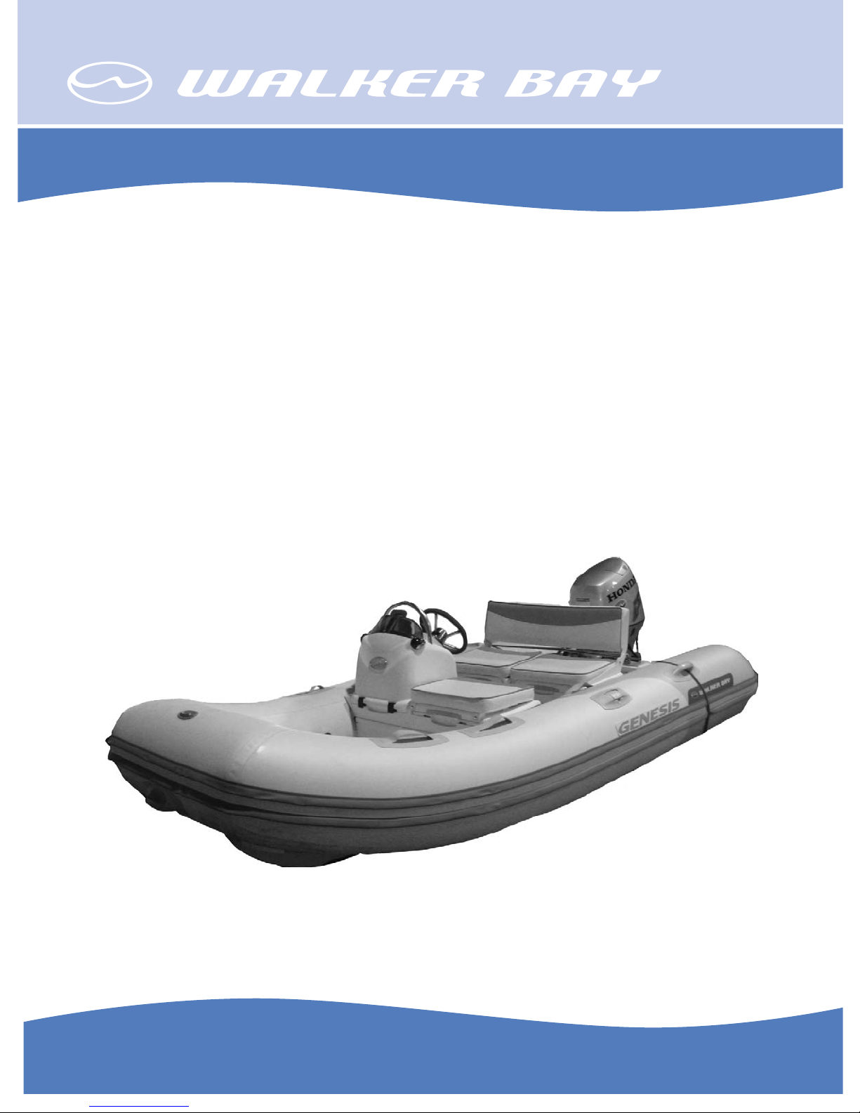
Genesis Console
310 & 340
For Customer Service or Technical Support visit www.walkerbay.com
Page 2

INTRODUCTION
The Genesis Center Console package is a modular retrofi t system which allows
you to upgrade the 310 and 340 model Genesis RIB’s as either a Deluxe
Genesis Console RIB or as a scaled down Light Genesis Console runabout/
tender. This package provides the fi rst fully integrated injection molded center
console to the market, and is designed specifi cally for Walker Bay’s award
winning Genesis line.
Space and storage were two of the primary attributes Walker Bay took into
account when designing these packages. The console’s ergonomic design
provides the driver with more foot room, creating a more comfortable riding
position, and the integrated seat storage compartments make effi cient use of
space. The center console has two compartments, one designed to take a
battery and the other for gear. The console itself is sold as a Basic Console Kit.
In addition to the standard Basic Console Kit (P/N 925100), two deluxe kits can
be purchased which add additional comfort, storage and lighting:
The Deluxe Tender Kit (P/N: 925140) comes with a deluxe driving seat and
several cushions for added comfort. The seat has an integrated, hinged
backrest that lifts to reveal two large water resistant storage compartments
underneath, one of which has a secure ventilated area designed to hold a 3gallon gas tank in place.
The Electrical & Lighting Kit (P/N: 925180) provides dual color directional lights
and a customer wiring harness which attaches to the center console itself. This
kit also comes equipped with a 360o rear light which attaches to the back of
the rear seat frame.
The Basic Console Kit is meant to be installed with the Genesis 310FTL, whereas the Basic Console Kit, Deluxe Tender Kit and Electrical Kit can be purchased
as a package, with either the Genesis 310FTD or Genesis 340FTD. These three
kits, when combined with Walker Bay’s larger Deluxe boats, create a truly
deluxe package at a very competitive price.
Please visit www.walkerbay.com if you need more information of the Genesis
Console boats, or call 1 - 888 - 449 2553.
Assembling Instruction
for Genesis Console 310 & 340
Rev Date: TH.05.26.08
P/N 925225
2
Page 3

CONTENTS
Introduction ...................................................... 2
Boating Safety Signs & Symbols ............................. 4
Completed Boats ................................................. 5
925100 Basic Console Kit ............................... 6 - 12
Steering Wheel .................................................. 7
Console and Seat ......................................... 7 - 12
925180 Electrial/Lighting Kit ............................... 13
Side Lights ....................................................... 14
Switch Panel ..................................................... 15
Pole Light ......................................................... 16
925140 Deluxe Tender Kit .................................. 17
3
Page 4
BOATING SAFETY SIGNS AND SYMBOLS
This is the safety alert symbol. It is used to alert you to potential personal
injury hazards. Obey all safety messages that follow this symbol to avoid
possible injury or death.
DANGER
Indicates an imminently hazardous situation which, if not avoided, will result in death or
serious injury or substantial property damage.
WARNING
Indicates an imminently hazardous situation which, if not avoided, could result in death
or serious injury or property damage.
CAUTION
Indicates an imminently hazardous situation which, if not avoided, may result in
property damage.
CAUTION
Used without the safety alert symbol indicates a potentially hazardous situation,
which, if not avoided, may result in property damage.
NOTICE
Indicates installation, operation or maintenance information which is important but not
hazard related.
4
Page 5

Completed Boats:
Front View:
Left View:
Right View:
5
Page 6

925100 Basic Console Kit (Remote Steering Kit)
The followings will cover the installation of the Console Kit.
The Console Kit have the following parts:
A. The Console and Seat Assembly
B. Components
o
n
w
n Console and Seat Assembly with Steering Cable
u
p
q
r
v
s Steering Wheel Cap
s
t
w
o Deluxe Seat Tray (white)
p Ratchet Seat Clip Adapters with release straps
q Console Seat Cap (black)
r Accessory Holder (white)
t Steering Wheel
u Ratchet Seat Clips
v Cable Sheathing
w Seat Box lock-down screws
CAUTION
z Before proceeding to install the console, read this manual carefully, and check whether you have
received all components as shown in the pictures above.
z Do not lock the seat into the ratcheting adapters until you are completely satisfi ed with your
installations of all the cables (steering, electrical, fuel, etc.) and have tested the functioning of them.
Also cover the cables with the white cable sheathing provided.
Pushing and locking down the seats should be the fi nal step of assembling.
z If you have any questions during assembling, call Walker Bay at 1-888-44 WALKER.
6
Page 7

STEP ONE: INSTALLING THE STEERING WHEEL
1. Remove the nut and washer from the steering
shaft, slide the steering wheel down on the shaft,
put the washer and nut back and tighten with a 3/4”
deep-well socket wrench.
2. Install the steering wheel cap by fi rstly loosen-
ing the small bolt on the side of the steering wheel
housing with a small fl at screwdriver, insert the cap
into place, and re-tighten the bolt.
STEP TWO: INSTALLING THE CONSOLE & SEAT ASSEMBLY
1. Infl ate the tubes of the boat to full air pressure.
Prepare a bottle of clear soap water (note: do not
use colored soap).
2. Spray soap water into the front seat patches
where the console will be mounted. Spray all 4
patches.
7
Page 8

3. Insert the ratchet clip adapter into the seat
patches from below. The pull strap should face
down and the opening of the adapter should face
up.
4. Push the adapter all the way up until it sits
fi rmly inside the seat patch. Repeat this with the
other adapter, also with the strap facing down.
5. Install the other pair of adapters on the other
side of the tube in the same way.
7. Note that the rachet clips should be inserted
that they align with the curve of the infl ated
tubes. Pull down until they lock.
6. Open the lid of the console and the seat,
and fi nd the slots on the edges to insert the
rachet clips.
8. Position the console & seat above the
opening of the adapters, and guide the rachet clips into the adapter.
8
Page 9

CAUTION
z Do not lock down the console until you are satisfi ed with the set-up of the entire boat. Complete the
installation of all other controls, gauges, cables and wires fi rst.
z The seat racheting system is designed to hold the seat fi rmly in place. It could be diffi cult to remove
it from the tube once locked down.
9. Do not push down on one side fi rst. Work
on both sides until all 4 ratchet clips are fully
inserted and lock into place.
11. Slide the Console Accessory Holder down
along the rib on the opening.
10. Open the console and drop the black tray
in. The tray is to separate the battery compartment from the lower seat box.
12. It will fi t fi rmly in place. This tray is for
small accessories such as sun glasses.
9
Page 10

13. The next step is to further secure the seat
box to the fl oor. Look for the 2 sets of drywall
screws, small screws and washers in the box.
14. Open the seat lid, and look for the two
rounded spots at the center of the bottom of the
seat box. They are the positions for the screws.
15. Use a #2 Philips screwdriver to drill the drywall screw down into the hole. Drill slowly until
the screw stops.
WARNING
Use the 2 pre-set positions for drilling only.
Do not drill on the other places on the fl oor or near the tube, or you could drill a hole through
the hull and cause permanent damage and cause the boat to leak.
10
16. Place the washer on top of the drywall
screw head, and drill the smaller screw right
into the head of the drywall screw. Drill slowly
until it stops.
Page 11

17. The completed lock-down screws. Do
exactly the same with another set of screws
at the other spot.
18. If you are not installing the Deluxe Seat & Cushion
Kit, you can install the original Genesis seat on the
2nd set of seat patches.
19. Lift the seat lid and drop in the seat tray.
Now the installation of Console is complete.
20. Battery is to be placed inside the console,
under the steering wheel helm. Use the Battery
Tie-down Brackets and straps provided to secure
the battery fi rmly in place.
NOTE
1. Battery:
Please use a starting battery which is no taller than 8 inches, due to the limited space inside
the console. The following battery has been tested by us and has been working well with the
Honda 30 hp motor we installed.
Optima Batteries - Blue Top for marine use
P/N: 34M (8006-006) - unboxed
P/N: 34M (9006-006) - boxed
Specs: BlueTop®; Marine Battery; Group 34M; Cold Crank Amps 800; Crank Amps 1000;
Reserve Capacity 110; Ampere Hour 50; Top Terminal.
Dimensions: L - 10 in.; W - 6 7/8 in.; H - 7 13/16 in.
11
Page 12

NOTE
2. Steering Cable:
The steering cable cannot be bent at a sharp angle, or steering performace will be affected,
or the cable could come loose during operation.
We suggest that the black tray between the console and under seat box to be removed, and
the steering cable to be guided down towards the bottom of the seat box. And then it could
come out of the seat box from the lower starboard side via the round opening, and along
below the tube all the way to the motor at the rear.
3. Fuel Tank:
Since the tray in the battery compartment is to be removed because of the steering cable,
you MUST NOT place the fuel tank inside the lower seat box under the console.
According to marine safety regulations, the battery and the fuel tank must be separated.
Walker Bay recommends that the fuel tank to be placed under the rear seat, if you install the
Genesis seat there.
If you are going to install the Deluxe Tender Kit, you will have a similar seat box under the
rear seat, in which the fuel tank can also be placed.
There is a warning lable in the battery compartment showing such a warning (see below).
If this label is missing or worn out, you could order a replacement by calling us at 1-888-44
WALKER. The part number is: ____________.
4. Installing Throttle Control and Outboard Motor:
For Outboard Motor installation instructions, please see owner's manual of the Genesis boats
by Walker Bay Boats.
For throttle controls, there are 2 types that can be installed: fl ush mount, or side mount.
Please follow the installation instructions that come with the throttle control unit that you are
going to use.
Note: If you are installing side lights, please make sure that you position the throttle control
far back enough from the starboard light so the handle, when in full throttle position, will not
interfere with the light.
12
 Loading...