

Walkeraid 4200-100 Instruction Manual
A PRODUCT
Instruction Manual for Rehabilitation Facilities
Model 4200-100
A Computer-Based DME Device
Follow this instruction manual to ensure
safe use of the Walker Alarm Device.
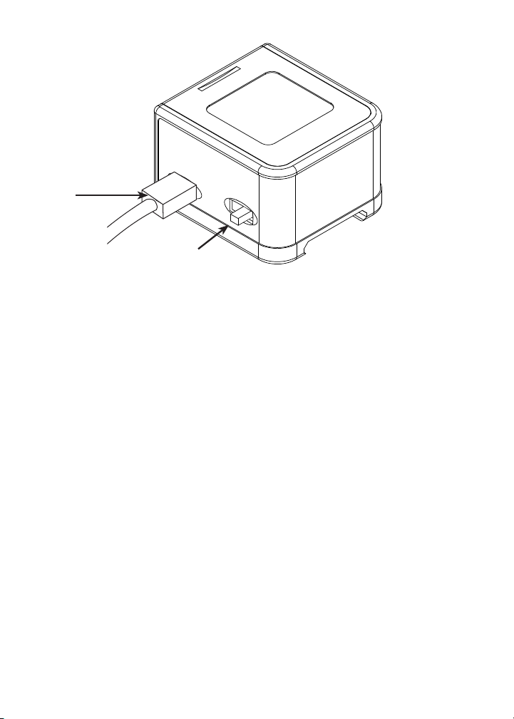
START UP
CHARGING
CABLE
ON/OFF
SWITCH
CHARGING
IMPORTANT: Charge the Walker Alarm at least
6 hours; but not more than 24 hours.
➊ Turn switch to OFF position
➋ Plug in charging cable to the wall outlet and plug charging
cable into the side charging port on the
Walker Alarm.
A YELLOW LED lights during charging.
A GREEN LED indicates a full charge.
The battery manufacturer recommends not to leave
the battery in a charge function over 24 hours.
LOW BATTERY INDICATION
After 8 hours or more of continuous normal use the YELLOW
Low Battery Light will start to ash indicating 10-15 left of
battery charge left. After the remaining 10-15 minutes is up,
the Walker Alarm will CHIRP and ash YELLOW for about 2
seconds and then shut off.
Note: Please read the information on lithium polymer batteries on page 10.
2
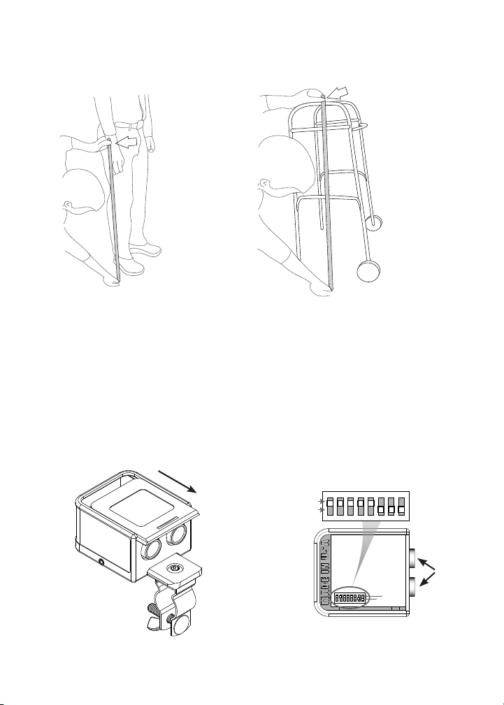
SUGGESTED BEST PRACTICE
Top View Lid Removed
Select, measure and adjust walker to patient.
STEP 1:
MEASURE FROM
WRIST TO FLOOR.
STEP 2:
WALKER IS
ADJUSTED TO
MEASUREMENT
FROM STEP 1
Follow the manufacturer’s suggested procedures to t each
style of walker.
SWITCH SET-UP
➊ Slide Cover open by
lightly pressing down and
forward on the rear of the
cover. If needed, gently lift
front with ngernail.
➋ To get the feel of the Dip
switches, move a switch
up or down with a tip of a
ball point pen, feel when
the switch engages into
the up or down position.
1
2 3 4 5 6 7 8
Up
Down
UP
DOWN
➌ Leave switches 7& 8 in the down position to maintain
factory settings.
SENORS
3
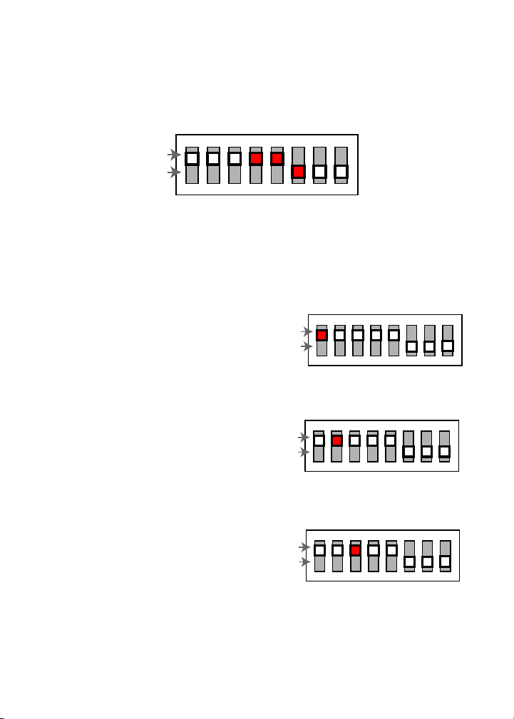
MATCHING WALKER ALARM TO PATIENT NEEDS
1
Up
Down
Switch 2: Beep Alarm On/Off
2345678
VIBRATE, ALARM, GLOW, DIP SWITCH SETTINGS:
1
Up
Down
Switch 1: Vibrate On/Off
2 3 4 5 6 7 8 1
Up
Down
Switch 2: Beep Alarm On/Off
2 3 4 5 6 7 8
Switch 3: Color Glow On/Off
VIBRATE, ALARM, GLOW, DIP SWITCH SETTINGS:
The Walker Alarm device as shipped from the factory comes
with 3 biofeedback controls TURNED ON or in the UP position:
1
2 3 4 5 6 7 8
Up
Down
Factory Switch Setting
Select which feature, and the number of features to be used
based on impairment and assessment.
1
SWITCH 1: Vibration Control.
The ON position activates the
VIBRATION sensory feature.
SWITCH 2: Sound Control.
The ON position activates the
BEEP audio alarm feature.
SWITCH 3: Light Control.
The ON position activates the
LED light visual feature that
ashes WHITE then RED or
Glows GREEN.
Up
Down
Up
Down
Up
Down
2345678
Switch 1: Vibrate On/Off
1
2 3 4 5 6 7 8
Switch 2: Beep Alarm On/Off
1
2 3 4 5 6 7 8
NOTE: The GREEN GLOW give the person the instant gratification
that they are using the walker correctly.
4
 Loading...