

Page 1

mmzseap,rmair
**MMUS, OfilifiC11110101
RC HIHICOnfer
User Handbook
Specifications:
Main Rotor Dia. : 105.5mm
Overall Length: 145mm
Overall Width: 145mm
Receiver: RX2646H-DS
Software: WK-REMOTE
Transmitter: 2402 D/DEVO-4/6/7/7E/8S/10/12S/F4/F7
All-up Weight: 89g( Battery included)
Gyro: Six-Axis
Drive Motor: HS-8520
Battery: 3.7V 600mAh Li-Po
Features:
1)
Equipped with Wi-Fi module, support 1phone, !pad series products.
2)
Support Walkera Devo series Transmitters.
3)
The usage of 6-Axis gyro and lntergration design of the flight status control, ensures the precise location of
the flight performance.
4)
Adopting quad-motors Ratio Gear driving system, stable flight, and can easily do the front and back,
left and right rolls.
5)
The simple and compact modularized design, easy to install and maintain.
6)
Flight time will be up to 10 minutes on a 3.7V 600mAh Li
-
Po.
7)
The RX firmware can be Updated Online (required UP02 upgrade cable and adapter ).
Page 2

Support iphone and Devo Seris Radios
(MODEL with WiFi module)
clek)enticy.
DIY Video Version
Upgrade WK series
radios with FPV function!
OR W100S
PHOTO
1:11
CAMERA
DEVO
REV ROE
n
Available on the
U App Store
Adopted with ratio gear motor
Doubled the flight time, up to 10 minutes
Lower power loss and improvement in efficiency
More stable and easier to control
Support the FPV radio DEVO F4/F7 and to enjoy the FPV videos
(exchange the WiFi module to TX5805/5806 module)
Support WK/Spectrum/Futaba/JR series Radios and
DIY Video with iPhone or iPad.
(Model With WiFi module and needed to complete RC Cube)
Page 3
Contents
01. Forewords
1
8.4 Function setting
7
02. Safety matters needing attention
1
8.4.1 Base setting
7
2.1 Important Statement
1
8.4.2 Expert setting
8
2.2 Safety matters needing attention
1
8.5 Operating methods
8
1 Manual flight control (take
5.
(1) Far away from obstacles and people
1
8.5.1
8
Mode 1 as example)
(2) Keep away from humidity
1
8.5.2 Gravity sensor control when flying
8
( take sample for mode 1)
(3) Proper operation and maintenance
1
(4) Avoid flying alone
1
8.6 Matters needing attention
9
(5)
Safety operation
2
09. Transmitter control
10
(6) Away from highly spinning parts
2
9.1 Transmitter setup
10
(7) Protect from heat
2
9.1.1 DEVO-6/7/7E/8S/10/12S/F4/F7
10
(optional radio)settings
2.3 Attention before flight
2
9.1.2 2402D/DEVO-4 radio reverse setting
11
03. Definition of UFO Orientation
3
9.2 DEVO-F4/F7 with TX5805/TX5806(FCC)
11
Video Select
04. Standard equipment
3
9.2.1 TX5805 Transmitting channel selection
11
9.2.2 TX5806(FCC) Transmitting channel selection
11
05. Additional Instruction
4
9.3 Flight Modes switches of the Receiver
11
06. Setup of the RX2646H-DS receiver
4
9.3.1 With DEVO-4/F4 radio
11
6.1 RX2646H-DS receiver features
4
9.3.2 With DEVO-6/7/7E/8S/10/12S/F7 radio
12
6.2 Function of receiver
5
9.3.3 With 2402D radio
12
6.3 Adjustment of receiver
5
9.4 Turn on the power
13
6.4 Matters needing attention
5
9.4.1 Turn on the power
13
9.4.2 Matters needing attention
13
07. Instruction for GA006 Charger
6
9.4.3 Trouble shooting a flashing receiver
LED
13
after connecting the power cable
08. WK-REMOTE software control
6
9.5 Disconnect the power
14
8.1 Software Installing
6
9.6 Flight control
14
8.2 Connecting instruction
6
9.7 Trimming the flight actions
15
8.3 Control interface instruction
6
9.8 Flight practice
16
Page 4
9.8.1 Flight practice for the beginner
16
10.5.2 Gravity sensor control when flying
21
( take sample for mode 1)
(1) Matters needing attention
16
10.6 The Usage of mobile extended line(Optional)
22
(2) Steps
16
10.7 MTC-01 for WK Series radios function manual
22
9.8.2 Advanced practice
17
10.8 Update Online
23
(1) Frog-hopping practice
17
10.9 Charger
24
(2) Practicing controlled take off and landing
17
10.10 Matters needing attention
24
(3) Practicing square flight
17
(4) Figure eight practice
17
9.8.3 Roll flight practice
18
10. MTC-01 control
19
10.1 MTC-01 controller module illustration
19
10.2 Download Software
19
10.3 Method
19
10.3.1 Active RC-COPTER software
19
10.3.2 Following picture shows instruction
in the control interface
19
10.3.3 Binding
20
10.4 Function setting
20
10.4.1 Model select
20
10.4.2 Reverse setting
20
10.4.3 Vibration switch
20
10.4.4 AUX trims
20
10.4.5 Channel Select
20
10.4.6 Mode switch
20
10.4.7 Reset
21
10.4.8 Throttle curve , Dual Rate and
21
Exponential curve: no need to set
10.5 Operating methods
21
10.5.1 Manual flight control (take
21
Mode 1 as example)
Page 5
01
Forewords
02
Safety matters
needing
attention
moo
2-aiGHz
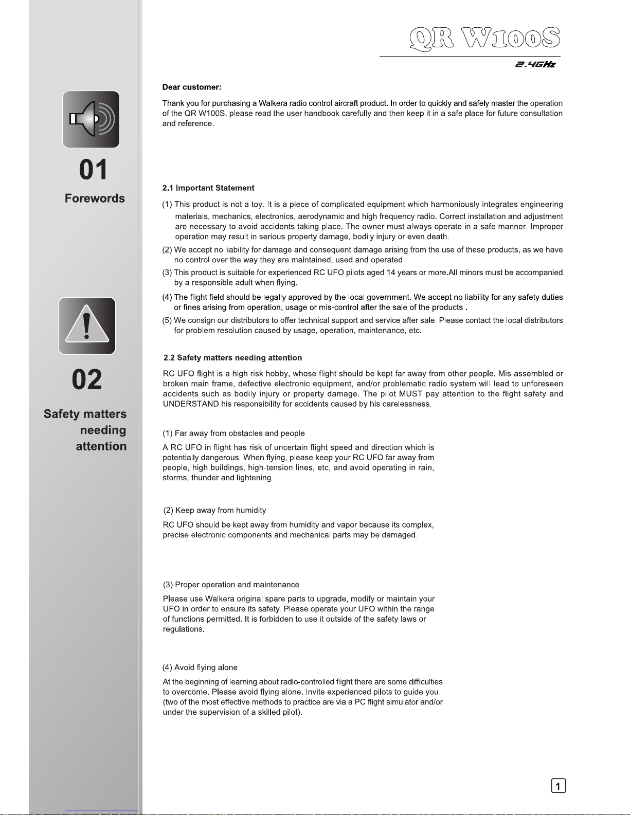
Dear customer:
Thank you for purchasing a Walkera radio control aircraft product. In order to quickly and safely master the operation
of the QR W100S, please read the user handbook carefully and then keep it in a safe place for future consultation
and reference.
2.1 Important Statement
(1)
This product is not a toy. It is a piece of complicated equipment which harmoniously integrates engineering
materials, mechanics, electronics, aerodynamic and high frequency radio. Correct installation and adjustment
are necessary to avoid accidents taking place. The owner must always operate in a safe manner. Improper
operation may result in serious property damage, bodily injury or even death.
(2)
We accept no liability for damage and consequent damage arising from the use of these products, as we have
no control over the way they are maintained, used and operated.
(3)
This product is suitable for experienced RC UFO pilots aged 14 years or more.All minors must be accompanied
by a responsible adult when flying.
(4)
The flight field should be legally approved by the local government. We accept no liability for any safety duties
or fines arising from operation, usage or mis-control after the sale of the products .
(5)
We consign our distributors to offer technical support and service after sale. Please contact the local distributors
for problem resolution caused by usage, operation, maintenance, etc.
2.2 Safety matters needing attention
RC UFO flight is a high risk hobby, whose flight should be kept far away from other people. Mis-assembled or
broken main frame, defective electronic equipment, and/or problematic radio system will lead to unforeseen
accidents such as bodily injury or property damage. The pilot MUST pay attention to the flight safety and
UNDERSTAND his responsibility for accidents caused by his carelessness.
(1)
Far away from obstacles and people
A RC UFO in flight has risk of uncertain flight speed and direction which is
potentially dangerous. When flying, please keep your RC UFO far away from
people, high buildings, high-tension lines, etc, and avoid operating in rain,
storms, thunder and lightening.
(2)
Keep away from humidity
RC UFO should be kept away from humidity and vapor because its complex,
precise electronic components and mechanical parts may be damaged.
(3)
Proper operation and maintenance
Please use Walkera original spare parts to upgrade, modify or maintain your
UFO in order to ensure its safety. Please operate your UFO within the range
of functions permitted. It is forbidden to use it outside of the safety laws or
regulations.
(4)
Avoid flying alone
At the beginning of learning about radio-controlled flight there are some difficulties
to overcome. Please avoid flying alone. Invite experienced pilots to guide you
(two of the most effective methods to practice are via a PC flight simulator and/or
under the supervision of a skilled pilot).
1
Page 6
02
Safety matters
needing
attention
(9_4 wzoo
O
2.A1Gffs
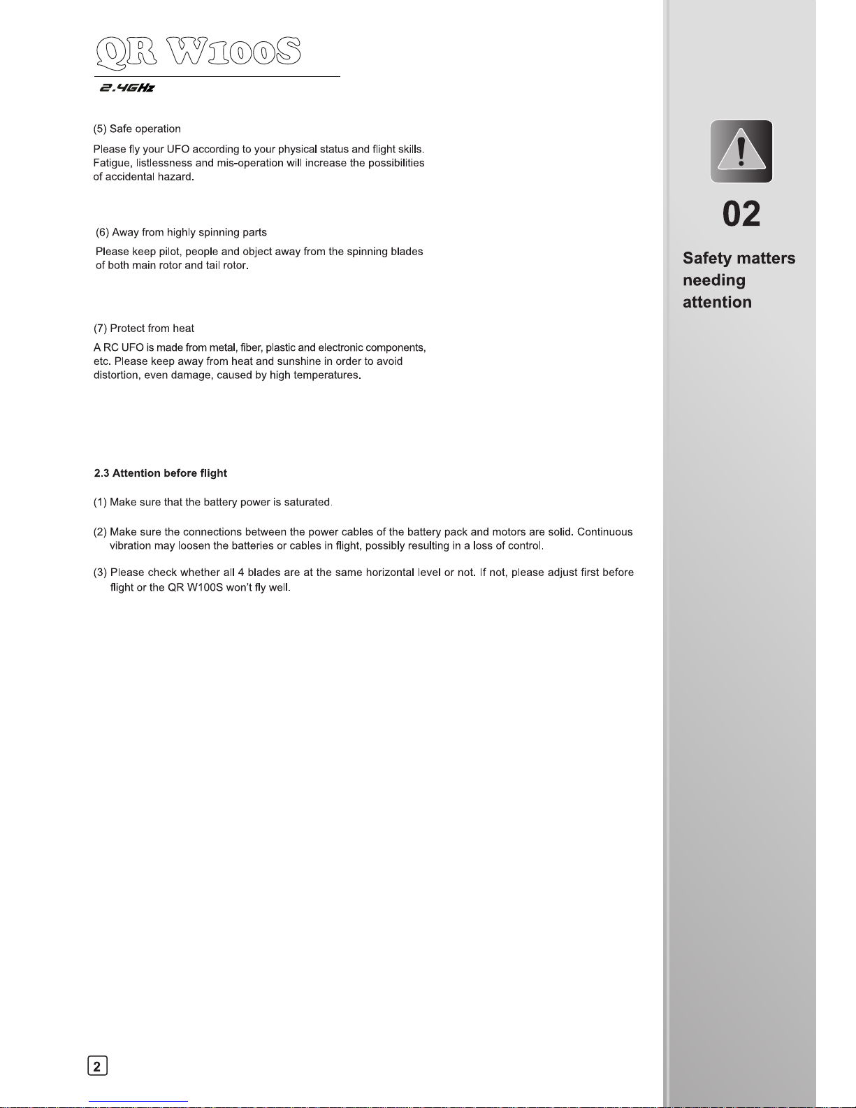
(5)
Safe operation
Please fly your UFO according to your physical status and flight skills.
Fatigue, listlessness and mis-operation will increase the possibilities
of accidental hazard.
(6)
Away from highly spinning parts
Please keep pilot, people and object away from the spinning blades
of both main rotor and tail rotor.
(7)
Protect from heat
A RC UFO is made from metal, fiber, plastic and electronic components,
etc. Please keep away from heat and sunshine in order to avoid
distortion, even damage, caused by high temperatures.
2.3 Attention before flight
(1)
Make sure that the battery power is saturated.
(2)
Make sure the connections between the power cables of the battery pack and motors are solid. Continuous
vibration may loosen the batteries or cables in flight, possibly resulting in a loss of control.
(3)
Please check whether all 4 blades are at the same horizontal level or not. If not, please adjust first before
flight or the QR W100S won't fly well.
2
Page 7
131
•
QR W100S
2.giG
Hz
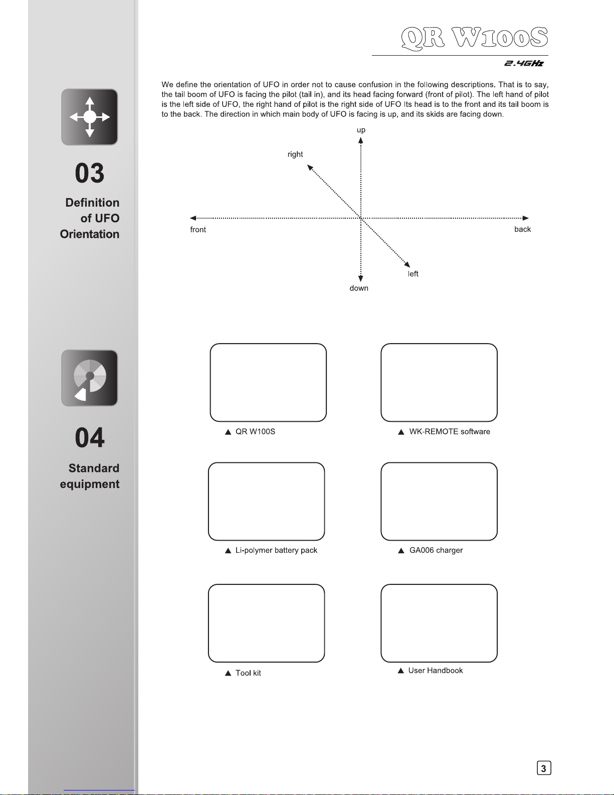
We define the orientation of UFO in order not to cause confusion in the following descriptions. That is to say,
the tail boom of UFO is facing the pilot (tail in), and its head facing forward (front of pilot). The left hand of pilot
is the left side of UFO, the right hand of pilot is the right side of UFO Its head is to the front and its tail boom is
to the back. The direction in which main body of UFO is facing is up, and its skids are facing down.
up
A
right
front
•
Li-polymer battery pack
•
Tool kit
•
GA006 charger
•
User Handbook
•
WK-REMOTE software
03
Definition
of UFO
Orientation
31
04
Standard
equipment
Page 8
CW CCW
CCW CW
9. Gyro sensitivity adjust knob
8. Signal indicator light
7. Upgrade channel two
6. Upgrade channel one
5. Power wire
05
Additional
Instruction
06
Setup of the
RX2646H-DS
receiver
2.‘IGHz
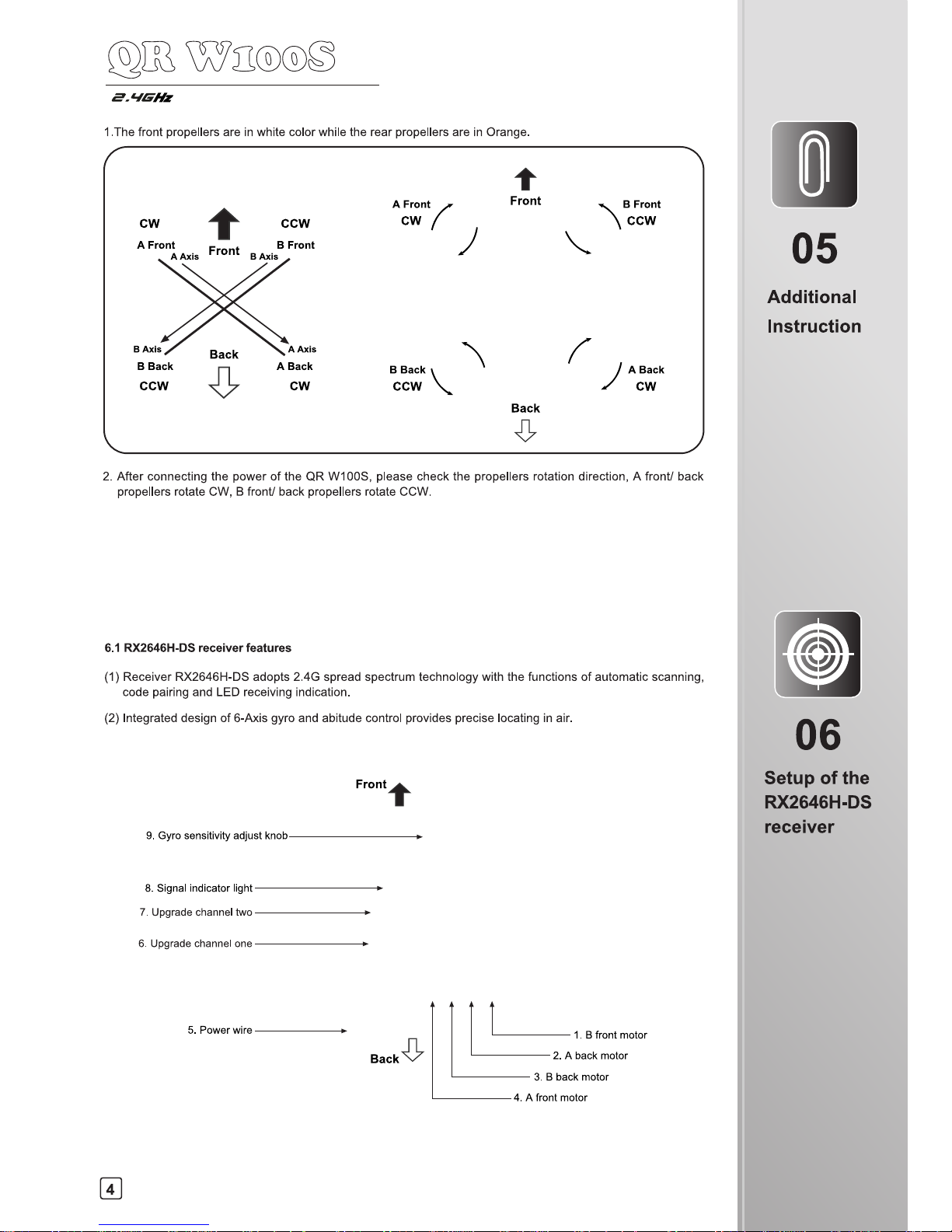
1.The front propellers are in white color while the rear propellers are in Orange.
2. After connecting the power of the QR W100S, please check the propellers rotation direction, A front/ back
propellers rotate CW, B front/ back propellers rotate CCW.
6.1 RX2646H-DS
receiver features
(1)
Receiver RX2646H-DS adopts 2.4G spread spectrum technology with the functions of automatic scanning,
code pairing and
LED
receiving indication.
(2)
Integrated design of 6-Axis gyro and abitude control provides precise locating in air.
4
Page 9
2.
1
-MHz
6.2 Function of receiver
S/N
Full name
Function
Connection
1
B front motor Connect to the B front motor wire.
Terminal is facing right.
2
A back motor
Connect to the A back motor wire.
Terminal is facing right.
3
B back motor
Connect to the B back motor wire.
Terminal is facing right.
4
A front motor
Connect to the A front motor wire.
Terminal is facing right.
5
Power wire Connect to the lipo battery.
6
Upgrade channel one
a.
Upgrade spare;
b.
Connect with the Wi-Fi module signal wire;
c.
Connects to the plug of TX5805/TX5806
(FCC) transmitter power wire;
Terminal is facing left.
7
Upgrade channel two
Upgrade spare or insert the bind plug to
clear the ID memory.
Terminal is facing left.
8
Signal indicator light
Display the status of received signal.
9
Gyro sensitivity
adjust knob
Adjust the gyro sensitivity of the front/back
/left/right /tail.
6.3 Adjustment of receiver
(1)
Adjust knob of the gyro: CW rotating increase the sensitivity of the Gyro, CCW rotating decrease the sensitivity
of the Gyro. The default setting is Middle, generally there is no need to trim.
(2)
Clear fixed ID in receiver: Insert plug terminal into upgrade channel two of the receiver to clear fixed ID
memory and disconnect plug terminal when the indicator of the receiver start to slowly flash.
(3)
Receiver upgrade:
(3.1) QR W100S control program upgrade can be downloaded online at Walkera Offical Website:www.walkera.com.
(3.2) QR W100S control program upgrade tool includes UP02 cable and UP02 Adapter.
UP02 Adapter
UP02
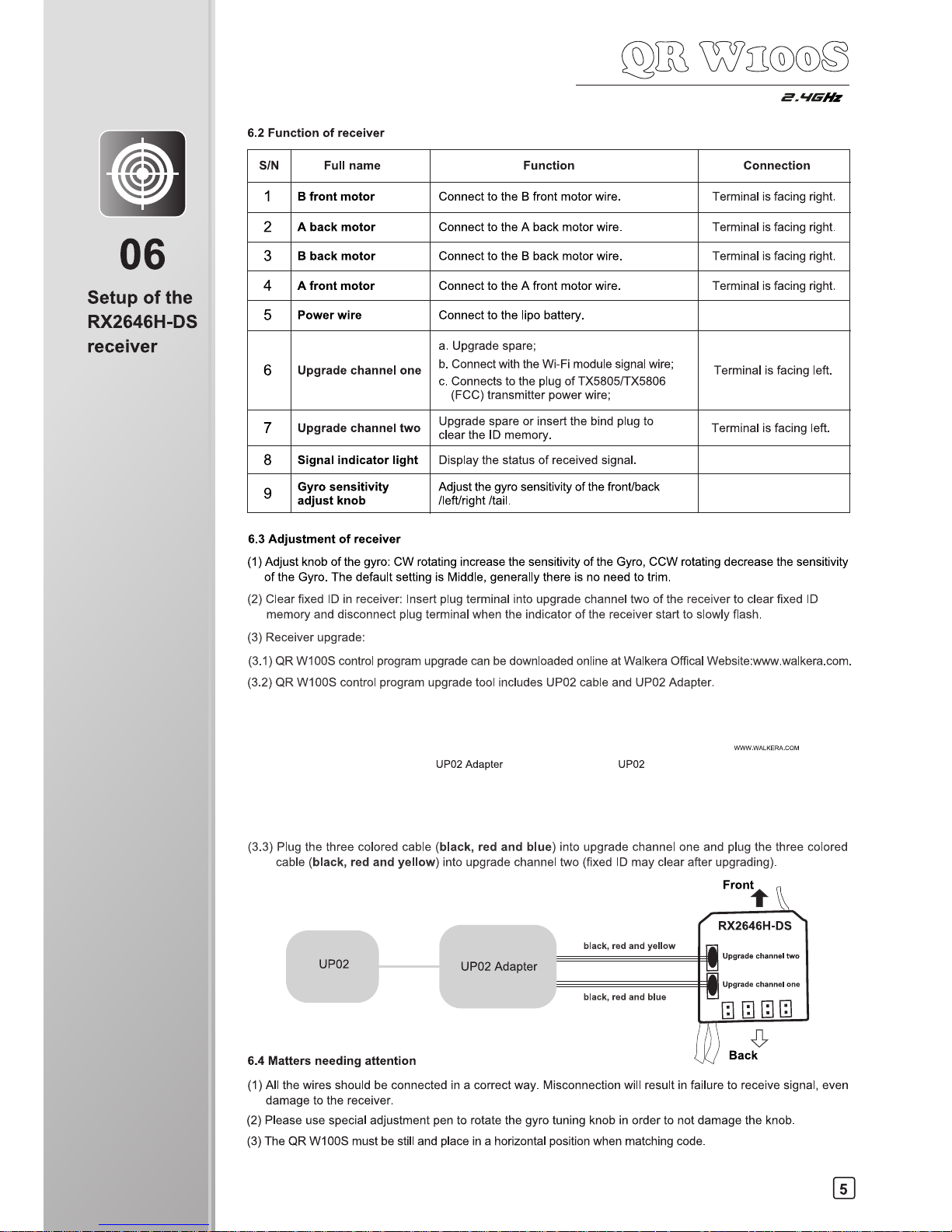
(3.3) Plug the three colored cable (black, red and blue) into upgrade channel one and plug the three colored
cable
(black, red and yellow) into upgrade channel two (fixed ID may clear after upgrading).
Frontt
RX2646H-DS
0
Upgrade channel two
Upgrade channel one
black, red and yellow
black, red and blue
UP02
UP02 Adapter
6.4 Matters needing attention
Back
(1)
All the wires should be connected in a correct way. Misconnection will result in failure to receive signal, even
damage to the receiver.
(2)
Please use special adjustment pen to rotate the gyro tuning knob in order to not damage the knob.
(3)
The QR W100S must be still and place in a horizontal position when matching code.
LJ
06
Setup of the
RX2646H-DS
receiver
5
Page 10

S
Wi Fi Signal
Setting
Rotate
Send the data
THRO/AILE stick
Booting interface
8.3 Control interface instruction
Camera
Return to the
previous interface
Video
Photo and View
ELEV/RUDD stick
Model Select interface
Control interface
07
Instruction
for GA006
Charger
IN=MI
Z
SN
O
08
WK-REMOTE
software
control
aia wzooc
2.
1
1Gliz
(1)
GA006 is suitable for 1 cell (3.7V) Li-ion or Li-polymer battery and can charge 2 pieces of batteries maximum
at the same time.
(2)
Please plug the pin of your battery into the jack of the GA006 first and then connect to the power. Otherwise,
the LED may not become red and the voltage may be higher than 3.8V. You need to disconnect the USB
power supply and reconnect it.
(3)
When USB power supply is well connected and battery is charging, the LED will become red. After your battery
is full charged, the LED will not become red.
8.1 Software Installing
The software is designed for iPhone or iPad, please download the software WK-REMOTE at APP Store.
8.2 Connecting instruction
(1)
Connect the UFO power and the indicator light will flash quickly.
(2)
Enter the iPhone or iPad setting interface to active the Wi-Fi. Then the WK******** could be found at the
Wi-Fi search list. If there is a "V" symbol, it means successful binding. Exit after finish.
(3)
Enter software in the iPhone or iPad and then enter Model Select interface. Touch icon 0 to enter control
interface. And then touch the icon (c of data transmission switch(data transmission switch is colorful). It means
successful binding if the UFO indicator light becomes solid. On the iPhone or iPad screen, there will be realtime video image shown. Then you are able to control the UFO.(Note: When flying, please keep away from
other Wi-Fi signal environment in case of interference)
6
Page 11

O
08
WK-REMOT
software
control
Iri)c-Dai))
•
Aileron •
• Rudder •
•
aT
Mode 4(Throttle stick on the left)
re ra, (ii) 0
a_f_i) (-6 6 -
4 .
- - ) (6)
•
Rudder •
• Aileron •
/----
t ....
3
• PI
P
/
al ,... ../
1 g
Mode 2(Throttle stick on the left)
Mode 3(Throttle stick on the right)
_LIGHz
8.4 Function setting
Touch in flight control interface to enter to setting menu, show as below:
Base setting
Expert setting
8.4.1 Base setting
Touch base setting icon shown as on above picture, there are Model select, Mode select, Reverse setting. Shown
as below:
Model select
MOD
Reset
Mode select
MODE:
Reverse setting
REVERSE:
ELEV AILE TIRO RUDD GYRO PIT
(1)
Model select: there are 4 model can be selected.
(2)
Mode select : there are 4 mode available. Throttle stick on the right (Model and Mode3) and throttle stick on
the left(Mode2 and Mode4).
(i)
] (ismii)
,
0 (i)
(is)
) (;-.--,-
)(6)
--.......
•
---- -
----.
•
m
.7
_
<
._
su
e
T
i
3
a)
•
•
Rudder •
—
•
•
•
Aileron •
Mode I (Throttle stick on the right)
7
Page 12

CXDOCICOCD©
C>00-DCDC)CDCD
08
WK-REMOTE
software
control
zoco
2_AIGHz
(3)
Reset: When touch this Reset icon, all settings will be reset to the factory original setting.
(4)
Reverse setting: Elevator, Aileron, Throttle, Rudder, Gyro, Pitch and so on, all of them are normal. Unselected
symbol is gray means normal options, selected the symbol is colorful means reverse setup.
8.4.2 Expert setting: It doesn't need any Expert setting.
8.5 Operating methods
8.5.1 Manual flight control (take Mode 1 as example)
(1) Throttle stick control: Press and hold the throttle
control ball and then pushed up, the motor rotates,
the higher it push, the faster the motor will rotate(fly
higher); The motor will slow down when push down,
the lower it push, slower the motor rotates.
(2) Aileron stick control (left and right): When moving
the AILE control ball left, the UFO accordingly flies
left; When moving the AILE control ball right, the
UFO accordingly flies right.
(3) Elevator stick control(forward and backward):
When moving the ELEV control ball up, the UFO
accordingly flies forward; When moving the ELEV
control ball down, the UFO accordingly flies
backward.
(4) Rotate control: When moving the RUDD control
ball left, the UFO accordingly rotate left(CCW);
When moving the RUDD control ball right, the
UFO accordingly rotate right(CW).
8.5.2 Gravity sensor control when flying( take sample for mode 1 )
Touch the gravity sensor button on the screen, colorful is ON while gray is OFF. Please refer to below Illustration:
Gravity Sensor key Non Active status Gravity Sensor key Active status
8
Page 13

S
•
08
WK-REMOT
software
control
_LIGHz
When switch the gravity sensor to colorful status, elevators and aileron control will be changed to gravity sensor
control mode(can be operated by one hand). the direction control show as below:
CrOC)®0®(7000
,\ 4
Tr '0
(1) Throttle stick control: Press and hold the throttle
control ball and then pushed up, the motor rotates,
the higher it push, the faster the motor will rotate(fly
higher); The motor will slow down when push
down, the lower it push, slower the motor rotates.
(2) Aileron stick control (left and right): When moving
the phone to the left, the UFO will fly to the left;
when moving the phone to the right, the UFO will
fly to the right (The control ball won't scroll in mode
1 and mode 4 while in mode 2 and mode 3, the
ball will scroll.)
(3) Elevator stick control(forward and backward):
When moving the phone to the front, the UFO
will fly forward; when moving the phone to the
back, the UFO will be backward. (The control
ball won't scroll in mode 1 and mode 4 while in
mode 2 and mode 3, the ball will scroll.)
8.6 Matters needing attention
(4) Rotate control: When moving the RUDD control
ball left, the UFO accordingly rotate left(CCW);
When moving the RUDD control ball right, the
UFO accordingly rotate right(CW).
(1)
Touch the icon C) for pause during the flight. Gray is OFF and forbid to use the control ball on the screen.
Touch the icon again to continue. Colorful is ON and active the control ball at the same time.
(2)
If the Wi-Fi can not to connect:
Possible causes
Solutions
The UFO battery is low. Confirm the battery is fully charged.
Wi-Fi can not search the network.
Please close the Wi-Fi and research with the net again.
(3)
If you need to change the UFO battery, please exit the software WK-REMOTE programe completely. When
the Wi-Fi search list is re-fresh again, please select the corresponding net to connect . After success binding
with the phone, please enter to the software WK-REMOTE again.
(4)
The WK-REMOTE software's maximum remote radius is 25 meters, so do not operate exceed this radius.
9
Page 14

09
Transmitter
control
Q`
.12,®clo
2_AIGHz
9.1 Transmitter setup
9.1.1 DEVO-6/7/7E/8S/10/12S/F4/F7(optional radio)seftings
(1) Type:Helicopter
(2) Swash type:1 Servo Normal
(3) Device Output
DEVO-6
DEVO-7 DEVO-7E
DEVO-F7
Gear
Pitch
FMOD SW
System
Active
Active
GEAR
AUX2
GEAR
FMD
ACT
ACT
Gear
AUX2
HOLD SW
FMOD SW
Active
Active
Gear
Pitch
AUX2
GEAR SW
System
FMOD SW
Active
Active
Active
DEVO-8S
DEVO-10
DEVO-12S
Gear
Pitch
AUX2
AUX3
GEAR SW
System
FMOD SW
RUDD D/R
Active
Active
Active
Active
Gear
AUX2
AUX3
AUX4
AUX5
GEAR SW
FMOD SW
RUDD D/R
AUX4 KB
AUX5 KB
Active
Active
Active
Active
Active
Gear
Pitch
AUX2
AUX3
AUX4
AUX5
AUX6
AUX7
GEAR SW
System
FMOD SW
AUX3 Lever
AUX4 Lever
AUX5 Lever
AUX6 Knob
AUX7 Knob
Active
Active
Active
Active
Active
Active
Active
Active
(4) Reverse switch settings
DEVO-6
DEVO-7
DEVO-7E
DEVO-8S
Elevator
Aileron
Throttle
Rudder
Gear
Pitch
Normal
Normal
Normal
Normal
Normal
Normal
ELEV
AILE
THRO
RUDD
GEAR
PITCH
AUX2
NORM
NORM
NORM
NORM
NORM
NORM
NORM
Elevator
Aileron
Throttle
Rudder
Gear
Pitch
AUX2
Normal
Normal
Normal
Normal
Normal
Normal
Normal
Elevator
Aileron
Throttle
Rudder
Gear
Pitch
AUX2
AUX3
Normal
Normal
Normal
Normal
Normal
Normal
Normal
Normal
DEVO-F4
DEVO-F7
DEVO-10
DEVO-12S
Elevator
Aileron
Throttle
Rudder
Normal
Normal
Normal
Normal
Elevator
Aileron
Throttle
Rudder
Gear
Pitch
AUX2
Normal
Normal
Normal
Normal
Normal
Normal
Normal
Elevator
Aileron
Throttle
Rudder
Gear
Pitch
AUX2
AUX3
AUX4
AUX5
Normal
Normal
Normal
Normal
Normal
Normal
Normal
Normal
Normal
Normal
Elevator
Aileron
Throttle
Rudder
Gear
Pitch
AUX2
AUX3
AUX4
AUX5
A
AUX6
AUX7
Normal
Normal
Normal
Normal
Normal
Normal
Normal
Normal
Normal
Normal
Normal
Normal
10
Page 15

09
Transmitter
control
9.1.2 2402D/DEVO-4 radio reverse setting
2402D
DEVO-4
ELEV
AILE
THRO
RUDD
NOR
NOR
NOR
NOR
ELEV
AILE
THRO
RUDD
NOR
NOR
NOR
NOR
Remark:
the switch in the "ON" position
for reverse (REV); the switch in the "ON"
reverse position for normal (NOR).
9.2 DEVO-F4/F7 with TX5805fTX5806(FCC) Video Select
move the cursor — to point to System Menu, press ENT to
— to point to Video Select, press ENT to Video Select setting
Press ENT to the Main Menu. Press UP or DN to
System Menu; Press UP or DN to move the cursor
interface. Press R or L to select Active. Press
DN to move the cursor — to point to Channel
item, press R or L to make the Number change
between 1 and 8. With the TX5805/TX5806
(FCC) transmitting channel,1-8 channels could
be choosed to receive the image signal. Press
ENT to confirm and then press EXT to exit.
Video Select
7.4V
—
Status
Active
Channel
1/8
Video Select
7.4V
Status
Active
Channel
1/8
9.2.1 TX5805 Transmitting channel selection
There are 8 different channels can be selected. You can choose the best frequency channel according to the
image quality like follows(The left code switch 1 is idle):
ON ON
ON ON ON ON ON
O
N
E E E
E
E
E
U E E
E
0
E
E E
E
E E E
E
E E
E E
E
1 2 1
2
1 2 1
2
1 2 1
2
1 2 1
2
1 2 1
2
1 2 1
2
1 2 1 2
1 2 1 2
Channel 1 Channel 2 Channel 3 Channel 4 Channel 5 Channel 6 Channel 7 Channel 8
code position code position code position
code position code position code position code position code position
Remark:
TX5805 Transmitting channel is corresponding to the video receive channel.
9.2.2 TX5806(FCC) Transmitting channel selection
There are 4 different channels can be selected. You can choose the best frequency channel according to the
image quality like follows:
ON
ON
ON
ON
U
U
0
E
1 2
1 2
1 2
1 2
Channel 2
code position
Channel 4
code position
Channel 6
code position
Channel 8
code position
Remark:
TX5806(FCC) Transmitting channel is corresponding to the video receive channel.
9.3 Flight Modes switches of the Receiver
9.3.1 With DEVO-4/F4 radio
Note:Please strictly refer to below operations.
(1) Pull the throttle stick to the lowest position, turn on the radio and connect the UFO battery, then comes to
the code pairing status. Disconnect the UFO battery after code pairing successfully. Then push the throttle
stick to the top position and connect the UFO battery, then comes to the code pairing status again. The receiver
indicator will flash between red and green alternately after code pairing successfully. That's the flight mode
switch status.(Shown as picture 1)
11
Page 16

(2) In Flight Mode switch status, push and
pull the Elevator Stick up and down four
times or above to change the Flight Mode
(Finish within 2 seconds). If red indicator
flashes quickly, it's normal flight mode.
If green indicator flashes quickly, it's roll
flight mode.
1. Push and pull the Elevator
2. It is in Normal Flight mode when the red
stick up and down four times
indicator flashes quickly, and it's in Roll Flight
or more(flnish in 2 second)
mode when the green indicator flashes quickly.
(The Flight Mode can be changed)
2. Turn on the 3. Turn on the radio and
4. After code pairing
transmitter
connect the UFO battery,
successfully,
then comes to the code
disconnect the
pairing status.
UFO battery
6. Connect the UFO
battery then comes
to the code pairing
status again.
7.After code pairing
successfully, the
receiver indicator will
flash between red and
green alternately.
1. Push the TX throttle stick to the top position
09
c):
2.AIG
Hz
(3) After choose the Flight Mode, pull the throttle stick at the lowest position, then flight available.
9.3.2 With DEVO-6/7/7E/8S/10/12S/F7 radio
Note:
Please set the FMOD switch as "ACTIVE" in the Output setting of Transmitter.
Type
Channel
Mode
Status
DEVO-6
Gear
FMOD Switch
Active
DEVO-7
AUX2
FMD
ACT
DEVO-7E
AUX2
FMOD Switch
Active
DEVO-8S
AUX2
FMOD Switch
Active
DEVO-10
AUX2
FMOD Switch
Active
DEVO-125
AUX2
FMOD Switch
Active
DEVO-F7
AUX2
FMOD Switch
Active
When the FMOD Flight Mode switch of the radio at "0" position, the receiver's red indicator
of Flight Mode turns solid as the Normal Flight Mode; and turns to normal flight mode; When
the FMOD mode switch of the radio at "2" position, (DEVO 7E at "1" postion), the receiver's
green indicator of Flight Mode flashing and turns solid as the Roll Flight Mode.
9.3.3 With 2402D radio
Note:Please strictly refer to below operations.
(1) Push the throttle stick to the top position, turn on the radio and connect the UFO battery , then comes to
the code pairing status.The receiver indicator of Flight Mode will flash between red and green alternately
after code pairing successfully. That's the Flight Modes switch status.
2. Turn on the transmitter
3. Connect the power
of the QR W100S
4. Begin the code
pairing process
5. The indicator of Flight Mode will
flash between red and green
alternately.
12
Page 17

1. Push and pull the Elevator
2. It is in Normal Flight mode when the red indicator flashes
stick up and down four times
quickly, and it's in Roll Flight mode when the green
or more(finish in 2 second)
indicator flashes quickly.(The Flight Mode can be changed)
Step 1
Step 2
Step 3
Step 4
Step 1: Open the battery compartment, Install the battery pack into
the battery compartment along the arrow direction.
Step 3: Pull down the throttle stick and throttle trim of transmitter to
the lowest position, and then move the elevator trim, aileron
trim, and rudder trim at the neutral positions, respectively.
Step 4: Connect the power cable of UFO to
receive signal from transmitter.
Step 2: Turn on the power of transmitter.
09
Transmitter
control
2-aiGHz
(2)
In Flight Mode switch status, push and pull the Elevator Stick up and down four times or above to change
the Flight Mode(Finish within 2 seconds). If red indicator flashes quickly, it's normal flight mode. If green
indicator flashes quickly, it's roll flight mode.
(3)
After choose the Flight Mode, pull the throttle stick at the lowest position, then flight available.
9.4 Turn on the power
9.4.1 Turn on the power
9.4.2 Matters needing attention
(1)
Please follow the rule: Power on the radio first then connect the battery of the quadcopter. After power on
the radio, connect the UFO battery in 10 seconds, the indicator starts flashing. the indicator becomes solid
after 1 to 3 seconds. After binding with the radio, the red indicator flash quickly means the radio binding
successfully.
(2)
If more than 10 seconds passed before the power cable was connected binding will fail. When binding fails,
disconnect the battery, tum off the transmitter and repeat step (1).
9.4.3 Trouble shooting a flashing receiver LED after connecting the power cable
Possible causes
Solutions
Code pairing failed.
Turn transmitter off then on and re-connect UFO
power cable.
The throttle trim and throttle stick of transmitter
are not at the lowest position.
Pull down the throttle trim and throttle stick to the
lowest position and re-code pair.
The transmitter battery is low or empty. Replace transmitter battery and re-code pair (re-bind).
The UFO battery is low or empty.
Replace the UFO battery with a fresh pack and re-code pair.
No function in receiver or transmitter. Replace faulty receiver or transmitter and re-code pair.
13
Page 18

14
Step 1: disconnect the power
cable of QR W100S
Step 2: turn off the transmitter.
Step 3: Remove the battery.
a c
,a w00000
2.41G
Hz
9.5 Disconnect the power
9.6 Flight control
Mode 1 (throttle stick at right hand)
1. When moving the aileron stick left or right, the
UFO accordingly flies left or right.
2. When moving the throttle stick up or down, the
UFO accordingly flies up or down.
3. When moving the rudder stick left or right, the head
of UFO accordingly flies left or right.
Mode 2 (throttle stick at left hand)
4. When moving the elevator stick up or down, the
UFO accordingly flies forward or backward.
1. When moving the aileron stick left or right, the
UFO accordingly flies left or right.
2. When moving the throttle stick up or down, the
UFO accordingly flies up or down.
09
Transmitter
control
Page 19

15
Q
cc
3 wzoocl
2-ziGHz
3. When moving the rudder stick left or right, the
head of UFO accordingly flies left or right.
9.7 Trimming the flight actions
(1)
Adjust the rudder trim
4. When moving elevator stick up or down, the
UFO according flies forward or backward.
Move the rudder trim right if the head of UFO flies leftward during taking off; otherwise move the rudder trim left.
(2)
Adjust the elevator trim
Move the elevator trim down if the UFO flies forward during taking off; otherwise move it up.
(3)
Adjust the aileron trim
Move the aileron trim right if the UFO flies leftward during taking off; otherwise move it left.
39
11
1
Transmitte
control
Page 20

09
Transmitter
control
9.8 Flight practice
9.8.1 Flight practice for the beginner
(1)
Matters needing attention
(1.1) Beginners should be supervised and guided by skilled pilots when learning.
(1.2) For the sake of safety, people should keep at least 5 meters away from the UFO during practice.
(1.3) Choose a spacious open ground without people and obstacles as the flight practice field.
(2)
Steps
(2.1) Practicing throttle control - stationary flight
Start by standing directly behind the UFO, tail closest to you and head/nose pointing away.Practice taking off
from the ground and then by slowly pulling down on the throttle stick, land it softly and horizontally. Repeat this
step until the throttle can be finely and carefully controlled.
When hovering,the tail rotor counteracts torque but also pushes UFO to the left. Don't forget to counteract this
effect using cyclic stick to the right and take off slightly inclined. It is important to hover vertically, stabilize UFO
at 1.5m height and then land it.
Mode 1
Mode 2
(2.2) Practice of aileron and elevator control
Mode 1
Mode 2
First increase throttle and enter a stable hover as practiced in the previous section. Next, use the elevator and
aileron sticks to purposely fly the UFO in a 'cross pattern' forwards, backwards, to the left and to the right. In
between each direction, return to hover over the take off point. Continue to repeat this step until it can be completed
with ease.
(2.3) Practicing rudder control
Mode 1
Mode 2
Enter a stable hover as practiced in step one, then practice rotating the head of the UFO to face left then back
to face right and back to face forwards (away from the pilot). Start with a rotation angle of 30 degrees or less
and gradually increase it as you become more comfortable and more experienced.
(2.4) Practicing circular flight
After mastering steps (2.1) to (2.3) with ease, please draw or mark a large circle on the ground. Fly your UFO
along this circular track until the flight is smooth and controlled.
You may wish to stand inside the circle at first to practice circular flight before needing to control the nose in
orientation.Fly circles in both directions and at a constant altitude to be comfortable with this step.
16
Page 21

Transmitter
4
control
2-aiGHz
9.8.2 Advanced practice
(1)
Frog-hopping practice
Repeat the take off and landing action using the throttle stick whilst maintaining a vertical path. Increase your
rate of ascent and descent gradually as you become more comfortable with the exercise. Be sure to slow down
in time when landing!
(2)
Practicing controlled take off and landing
Mark out an area on the ground as a landing pad to help practice deliberately taking off and landing from a setted
location. The process of take off and landing should be kept stable and as close to vertical as possible.
(3)
Practicing square flight
Take the take off point as the center to draw a square whose side length is about 2 meters. Fly your UFO along
the 4 sides and keep the flight height parallel to the line of sight. Make a 90 degree rotation at each corner of
the quadrangle to adjust the flight direction. Train your straight flight skills and 90 degree flight course control.
Fly in both directions around the circuit until familiar with the maneuver.
(4)
Figure eight practice
Once you have mastered the previous steps you can try flying smooth flat figure eights. Try to maintain the same
altitude during the entire flight path. Take care when flying where there is wind as it may cause the UFO to suddenly
rise or fall unexpectedly.
•
.
A
/ X/
N
-
Zr
N
17
Page 22

O
09
ransmitter
control
2.LIGHz
9.8.3 Roll flight practice
QR W100S can finish excited stunts actions,such as the front and back, right and left rolls.
Matters need to be attention when the first flight:
(1) Choose a spacious ground with soft grass to practice.
(2)
Select roll flight mode.
(3)
Advise beginner to increase servo distance of ELEV and AILE of the transmitter to 100%-110%. And can
adjust according to personal skill level. The default setting is 100%.
(4)
Practice of throttle stick: when UFO roll from normal status, the throttle stick need to be pulled down slowly;
Push up the throttle when it exchange normal status to roll. Please adjust according to personal skill level.
Mode 1 (throttle stick at right hand)
1. When moving the aileron stick left or right,
the UFO accordingly rolls left or right.
Mode 2 (throttle stick at left hand)
2. When moving the elevator stick up or down,
the UFO accordingly rolls forward or backward.
1. When moving the aileron stick left or right,
the UFO accordingly rolls left or right.
2. When moving the elevator stick up or down,
the UFO accordingly rolls forward or backward.
18
Page 23

19
(1) Find icon
on the phone interface and Active
(2)
Pressp-4 enter to control interface as
Q
cc3
wzoocl
2-ziGHz
10.1 MTC-01 controller module illustration
Upgrade channel 4
Upgrade channel 3
Upgrade channel 2
Upgrade channel 1
Controller module Plug
Data transfer Indicator
Power/Binding Indicator
Charging Indicator
1
1
10.2 Download Software
(1) For IPhone/IPad users, please go to the Apple Store (APP Store) to download the software RC-COPTER
and install it.
(2)
Android system ( above 2.0 version ), please visit the Walkera official website (www.walkera.com
) to download
RC-COPTER.apk and install it.
(3)
Click the software icon • , and install the software as per the instruction.
10.3 Method
Notice : Please adjust phone to Airplane mode (Please refer to the moble phone manual) in order to avoid
accident from calling interference.
10.3.1 Active RC-COPTER software
RC-COPTER software, as shown below.
shown below:
r
-
10.3.2 Following picture shows instruction in the control interface
CDC1****
Th1/4
0
Touch Screen Size Switch Key
©
Binding
0
Throttle direction indicator/Mode Switch key
C)
Gravity sensor C) Interface rotation
0
Binding Reset
®
Channel Display
®
THRO/AILE stick
®
Help
#
PIT curve
CI) D/R and Exponential curve
#
Throttle curve
#
Setup
4
ELEV/RUDD stick
#
Return to the previous interface
Apple's flight control
# #
T)" interface
10
MTC-01
control
Page 24

Touch Ell in flight control interface to enter to setting menu, show as below:
Apple setting interface
Reverse
Model select—.
I Mode Switch
Vibrate key
Reset
Mode select—.
AUX Trim
•
to
•
•
•
Channel Select—.
Switch(4ch & 6ch)
Reset
Reverse setting
10
MTC-01
control
I
05111314NO
•
Rudder •
• Aileron •
2.LIG
Hz
10.3.3 Binding
Plug the MTC-01 to the audio jack of phone, and turn on the MTC-01, the data transfer indicator is off after short
green flashing, and the power indicator keeps blue light. Press Binding Icon in the flight control interface.The
binding indicator is flashing in blue light(If the blue light don't flash, please press the Binding Reset Key in the
flight control interface and then press the binding key until the binding indicator blue light flashes). Connect the
UFO battery, the light becomes RED and flashing. The indicator of the UFO becomes solid after successful
binding, At this point, the binding could be finished with touching any stick of radio(The throttle stick is excluded),
or you can wait until the automatic binding by the phone(Longer time is needed). The data transfer Green light
flashes, the power BLUE indicator keeps solid. The RED indicator of UFO becomes solid after flashing(the receiver
programe is initialization ), the binding is successful .
10.4 Function setting
10.4.1 Model select: there are 4 model can be selected.
10.4.2 Reverse setting:The settings of elevator, aileron, throttle, rudder, gyro, pitch,etc are normal. If not select
as normal, select as reverse.
10.4.3 Vibration switch: If vibration switch turn on (not select as normal but turn on), when operate the control
ball during the flight, the phone will vibrate.
10.4.4 AUX trims: touch + or - to change the value according to quadcopter performance.
10.4.5 Channel Select: gyro sensitivity setting, touch + or — can change the values.
10.4.6 Mode switch
There are four switch modes. Right hand throttle (Mode 1, Mode
3);
Left hand throttle (Mode 2, Mode 4).
Mode I (Right hand throttle)
Mode 2(Left hand throttle)
Mode 3(Right hand throttle)
Mode 4(Left hand throttle)
20
Page 25

10
MTC-01
control
Q
cc3
wzoocl
2-ziGHz
10.4.7 Reset: All the settings will renew to factory settings when you Press this key.
10.4.8 Throttle curve , Dual Rate and Exponential curve: no need to set.
10.5 Operating methods
10.5.1 Manual flight control (take Mode 1 as example)
(1) Throttle stick control: Press and hold the throttle
control ball and then pushed up, the motor rotates,
the higher it push, the faster the motor will rotate(fly
higher); The motor will slow down when push down,
the lower it push, slower the motor rotates.
(2) Aileron stick control (left and right): When moving
the AILE control ball left, the UFO accordingly
flies left; When moving the AILE control ball right,
the UFO accordingly flies right.
(3) Elevator stick control(forward and backward):
When moving the
ELEV
control ball up, the UFO
accordingly flies forward; When moving the ELEV
control ball down, the UFO accordingly flies
backward.
(4) Rotate control: When moving the RUDD contro
ball left, the UFO accordingly rotate left(CCW)
When moving the RUDD control ball right, the
UFO accordingly rotate right(CW).
10.5.2 Gravity sensor control when flying( take sample for mode 1)
Touch the gravity sensor button on the screen, colorful is ON while gray is OFF. Please refer to below Illustration:
Gravity Sensor key Non Active status Gravity Sensor key Active status
21
Page 26

2.LIGHz
When switch the gravity sensor to colorful status, elevators and aileron control will be changed to gravity sensor
control mode(can be operated by one hand). the direction control show as below:
10
MTC-01
control
(1) Throttle stick control: Press and hold the throttle
control ball and then pushed up, the motor rotates,
the higher it push, the faster the motor will rotate(fly
higher); The motor will slow down when push
down, the lower it push, slower the motor rotates.
(2) Aileron stick control (left and right): When moving
the phone to the left, the UFO will fly to the left;
when moving the phone to the right, the UFO will
fly to the right( For !phone/ iPad , the controlled
ball can't scroll in Mode 1 and Mode 4 mode, but
can scroll in Mode 2 and Mode 3 mode).
I
(3) Elevator stick control(forward and backward):
When moving the phone to the front, the UFO will
fly forward; when moving the phone to the back,
the UFO will be backward( For !phone/ iPad , the
controlled ball can't scroll in Mode 1 and Mode 4
mode, but can scroll in Mode 2 and Mode 3 mode).
(4) Rotate control: When moving the RUDD control
ball left, the UFO accordingly rotate left(CCW);
When moving the RUDD control ball right, the
UFO accordingly rotate right(CW).
10.6 The Usage of mobile extended line(Optional)
(1)
Paste the magic stickers seperately at the back of MTC-01 and mobile phone.
(2)
Insert MTC-01 into parent end of signal line, the other end(dual-sound channel end) plugs into the audio jack
of phone.
(3)
Get the two magic stickers together for better flight control.The MTC-01 could also be hanged in the air without
pasting the magic stickers.
10.7 MTC-01 for WK Series radios function manual
(1) MTC-01 function for all radios with the simulated output signal socket: Connect MTC-01 to simulated output
signal socket in the radio(please refer to below Illustration), that can control the correspond channel receiver
of Devo series helicopters, The specific methods are as follows:
22
Page 27

,Iack,red and yellow
UP02 Adapter
black,red and blue
10
MTC-01
control
2-aiGHz
(2)
Connecting method: Insert MTC-01 into parent end of signal line, the other end plugs into the simulated output
signal of the radio(attention: some radio could turn on by itself when you plug into the simulated output signal
socket of the radio, in this case, don't need to turn on the radio after you connect it).(Shown as picture 1)
(3)
Please fix the MTC-01 onto the back of radio by using magic sticker. It could prevent the flight from poor
contact between the plugs.(Shown as picture 2)
(4) Binding:
(4.1) Turn on the MTC-01, the data transfer indicator light is off after short flashing, the power indicator light is Blue.
(4.2) Turn on the radio( as mentioned above, some radio could turn on by itself when you plug into the simulated
output signal socket of the radio, in this case, please don't turn on the radio first after you connect it), The
binding Indicator is flashing in Blue light. Connect the UFO battery, the light becomes RED and flashing.
The indicator of the UFO becomes solid after successful binding, at this point, the binding could be finished
with touching any stick of radio(he throttle stick is excluded). or you can wait until the automatic binding by
the phone(longer time is needed). The data transfer Green light flashes, the power BLUE indicator keeps
solid. The red indicator of UFO becomes solid after flashing(the receiver program is initialization ), the binding
is successful.(Please refer to the corresponding radio manuals for other flight specifications).
10.8 Update Online
There are two piece programe IC inside the MTC-01 module can be updated(Signal collection control programe
IC and RF control programe IC).
(1)
Please login Walkera official wesite to upgrade the MTC-01 Control Program.
(2)
Upgrade tool: UP02 cable and UP02 adapter.
VVWW.WALKERA.COM
UP02 Adapter
(3) Control Program IC upgrade by Signal: Plug the line binded with black, red and blue into the MTC-01 upgrade
channel 1, Plug the line binded with black, red and yellow into the MTC-01 upgrade channel 2.
UP02
23
Page 28

black,red and yellow
10
MTC-01
control
I
2.LIGHz
(4) Control Program IC upgrade by RF: Plug the line binded with black,red and yellow into the upgrade channel
3, Plug the line binded with black,red and blue into the upgrade channel 4.
black,red and blue
10.9 Charger
(1)
There is a 3.7V 80mAh LiPo battery in the controller. The battery can be charged with the USB wire.
(2)
The charge indicator becomes solid red when charge the battery, and will turn off Automaticlly after fully charged.
(3)
When MTC-01 power indicator and binding light flashing at the same time means you need to charge the
inner battery at once.
(4)
Charging Voltage:5V; Charging Current: <500mA.
10.10 Matters needing attention
(1)
The different hardware of Andriod phone may lead to the failure of using MTC-01. It's depends on the products
which you are using.
(2)
When using the phone to control, please adjust the volume at maximum to insure the normal data transfer.
Please don't adjust the volume after successful binding. Please unplug the UFO battery firstly, and then turn
off the MTC-01 after flight.
(3)
In case of emergency (A sudden flight for the UFO), please don't make the Mode switch after successful
binding.
(4)
If a short stop is needed during flight, please press the Binding Key in the flight control interface. Both green
light of the data transfer indicator and blue light of power indicator will be solid at the same time. The UFO
will be out of control if move the Control Stick in the flight interface. The short stop could be removed by
pressing the Binding Key slightly.
UP02 Adapter
UP02
24
Page 29

WARNING:
CHOKING HAZARD
C E
CY6
44
FC
Children under the age of 14 shout
be monitored by the experienced pilots.
On not Ay near high tension lines.or rainy day.
MADE IN CHINA
walkera
Add.: Taishi Industrial Park, Dongchong Town
Panyu District, 511475 Guangzhou
Tel.: (
8620 ) 8491 5115 8491 5116
Fax.: ( 8620 ) 8491 5117
Web: www.walkera.com
The
specifications of the RIC aircraft may
be altered without notice.
Email: heli@walkera.com
info@walkera.com
 Loading...