

Walkera TALI H500 Quick Start Manual
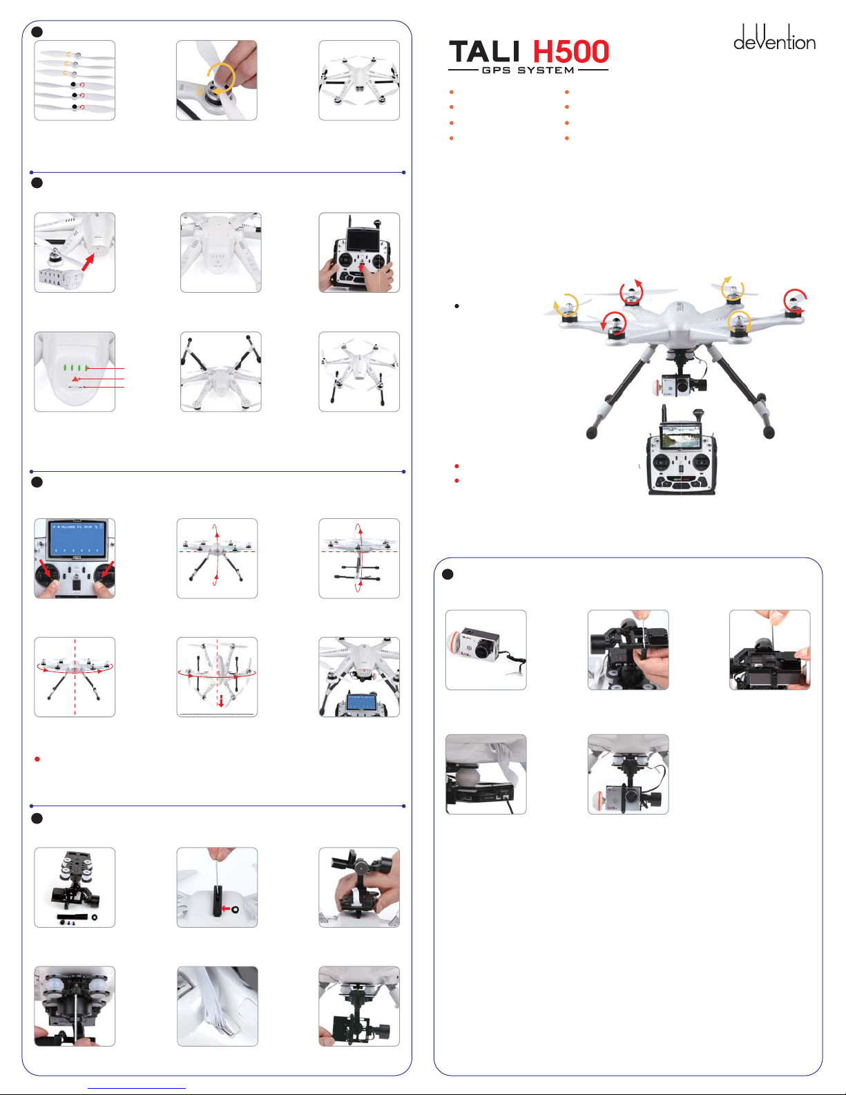
Installing the Propellers
1
1.1 Unpack the propellers, there are two kind
right-hand and left hand rotation, the rotation
is identified with arrows on the prop, and also
with the colored prop-top. You need 3 of each kind.
*We recommend balancing the propellers.
Check online for balancing instructions.
2
Installing Battery, Binding the radio, and extending the landing gear.
The Landing gear is shipped in the retracted position. DO NOT try to extend the landing gear by pulling on it.
We will deploy the landing-gear the first time the system is powered, please follow these instructions carefully.
1.2 Match the arrows on the propellers to the
arrows on the arm next to each motor. Screw
each propeller onto the motor, secure by hand,
no need for tools.
1.3 After installing the props, check each
propeller carefully.
Before EACH flight, Inspect propellers
for damage.
Auto Take off Altitude hold mode
Object Round fly mode
One key Return To Home
Hyper IOC mode Retractable Landing Gear
GPS telemetry
5.8G ghz video down link
Match with DEVO F12E
Quick Start Guide and Systems Flowchart
2.1 Install the fully charged battery
DO NOT turn on the battery until later.
*Please check the charger manual for
charging instructions
Power indicator
Power button
Power switch
2.4 Slide the power-switch to the ON position
then press on the triangle power button
for about 3-5 seconds, until the green
Power indicator lights up.
* The Landing gear will now unfold automatically.
* In the beginning of this process the light in the
arms flast red-green, this means the system is binding.
3
Compass Calibration
IMPORTANT: Make sure all TRIMs are in the center position, the trim value should be “0”, and that the motors are locked.
The aircraft should NOT be flashing RED-GREEN. By default, the motors will automatically be locked after the ID binding process.
For more details about locking and unlocking motors, see points 6 & 7.
3.1 Enter the calibration mode
Do this by moving both sticks DOWN and
to the middle position at the same time.
The aircraft will start a blinking fast RED-GREEN
3.4 HORISONTAL rotation Rotate the aircraft
around the YAW axis rotate smoothly in 90 deg
increments. Pausing 1 second for each 90 deg.
(0 / 90 / 180 / 270 / 360)
IMPORTANT: The first couple of flights, you may expereince the aircraft drifting,
This is normal, please continue to fly the aircraft manually, while the system inprove the calibration,
after 5-10 minutes land, lock the motors, this will save the improved settings.
Notice: The slight drifting may continue for a couple of batteries, you will notice significant improvement in the GPShold & stability after 4-5 batteries.
Notice: Always perform the calibration away from eletric fields and metal surfaces.
Trivia: Different brands have different calibration processes, the process is typically refered to as “the Calibration Dance”.
4
G-3D 3-axis brushless Gimbal installation
IMPORTANT: REMOVE the battery from the H500 while you install the gimbal
The gimbal is a high-performance eletromechanical design and should be handled with great care. AVOID using force when installing.
2.2 Turn TALI on its back. The belly and the
retractable legs should now be facing up.
MAKE SURE nothing is blocking the legs.
2.5 Turn the aircraft to its UP-right position.
The Red-Green LED flashing will stop shortly.
When it stops, the DEVO F12E and the H500 have
successfully connected to each other.
* This process is called “ID binding”
3.2 FORWARD rotation Rotate tilting the aircraft
forward rotate smoothly in 90 deg increments.
Pausing 1 second for each 90 deg.
(0 / 90 / 180 / 270 / 360)
4
Head vertical down
Ground
3.5 NOSE DOWN rotation Rotate the aircraft
facing the nose down. rotate smoothly in 90 deg
increments. Pausing 1 second for each 90 deg.
(0 / 90 / 180 / 270 / 360)
2.3 On the DEVO F12E, move ALL
switches to the “0” position, and move
the throttle to the lowest position.
Then turn on the DEVO F12E power.
2.6 After the successful binding
place the aircraft on a stable surface.
3.3 CLOCKWISE rotation Rotate the
aircraft around the roll axis rotate smoothly
in 90 deg increments. Pausing 1 second
for each 90 deg. (0 / 90 / 180 / 270 / 360)
3.6 Place the aircraft in normal position
The rapid RED-GREEN blinking will stop
This indicate that the calibration is finished
Disconnect the battery to save the settings.
Specifications:
Main Rotor Dia. : 233mm
Overall (L x W x H): 471 x 536 x 270mm
Weight: 2020g(Battery included)
Takeoff Weight: <2500g
Transmitter: DEVO F12E
Receiver: DEVO-RX705
Brushless Motor: WK-WS-34-001
Brushless ESC: WST-15AH (R/G)
Main Controller: FCS-H500
Battery: 22.2V 5400mAh Li-Po
M1/M3/M5 rotate in counterclockwise, motors are the dextrogyrate thread.
M2/M4/M6 rotate in clockwise, motors are the levogyrate thread.
5
Installing the iLook+ 1080p camera with 5.8ghz video link
IMPORTANT: NEVER POWER the iLook+ camera without the antenna installed.
Powering a video transmitter may cause damage to the transmitter.
5.1 Screw the short “mushroom” antenna
into the camera, use the included wrench
to gently secure the antenna, do not use force.
5.4 Connect the cameras power
cable to the power port on the
G-3D gimbal controller.
M2
M3
M1
5.2 Release the two M2x4 screws securing the
camera mounting bracket.
5.5 The iLook+ camera is now successfully
installed in your G-3D gimbal.
M4
M5
M6
5.3 Position the camera into the gimbal
“tray”, then secure the camera by
positioning the mounting bracket over
the camera, use the two M2x4mm
screws to secure the mounting bracket.
* There is a cutout on the mounting
bracket, this will fit around the lens.
** It is also possible to install a GoPro3
camera in this gimbal. IF you install a
GoPro, unscrew and remove the motor
cover on the pitch motor, this will adjust
the balance of the gimbal for the GoPro.
*** Use the switch on the end of the
iLook+ camera to select between
STILL and 1080p video.
**** You can change the video link
frequency on the back of the camera,
see the instructions included with
the camera for details on camera
operation.
4.1 Unpack the G-3D gimbal,
prepare the gimbal, the mounting
rail, rubber washer, screws and spring
loaded screw.
4.4 Install the springloaded
M3x12mm “finger screw” at the front
of the gimbal, this will secure the gimbal.
4.2 Put the rubber washer on the threaded hole on
the bottom of the H500, use the M3x8mm and
M3x10mm screws to install the gimbal “mounting
block” also refered to as the quick mount rail.
4.5 Connect the 9pin white data cable to the “complex
data port” on the bottom of the TALI, then connect the
cable to the back of the G-3D gimbal.
4.3 Slide the gimbal unto the quik mount
rail, the gimbal shouldslide from the front
of the aircraft towards the rear, gently
move it as far back as possible.
4.6 Make sure the gimbal move freely
in all directions. The G-3D gimbal is
now successfully installed.
6
Motor Unlock
After binding the DEVO F12E to the H500, Check that all trims are neutral,
the throttle stick ALL the way DOWN. the display should say 0% throttle
Check that ALL switches are in the UP position.
You can not start the motors in the GPS hold mode.
Gently push the throttle stick down and move the rudder (YAW) stick to the
left side. (on mode 2 radios throttle and rudder is the same stick)
You will see the RED / GREEN indicator LED’s will turn on, this indicate the
motors are unlocked,
Be very careful at this point, as pushing the thottle up will start the motors.
You can test by pushing the stick up a little, the motors should start.
For your safety, the motors will dis-arm again after 10seconds.
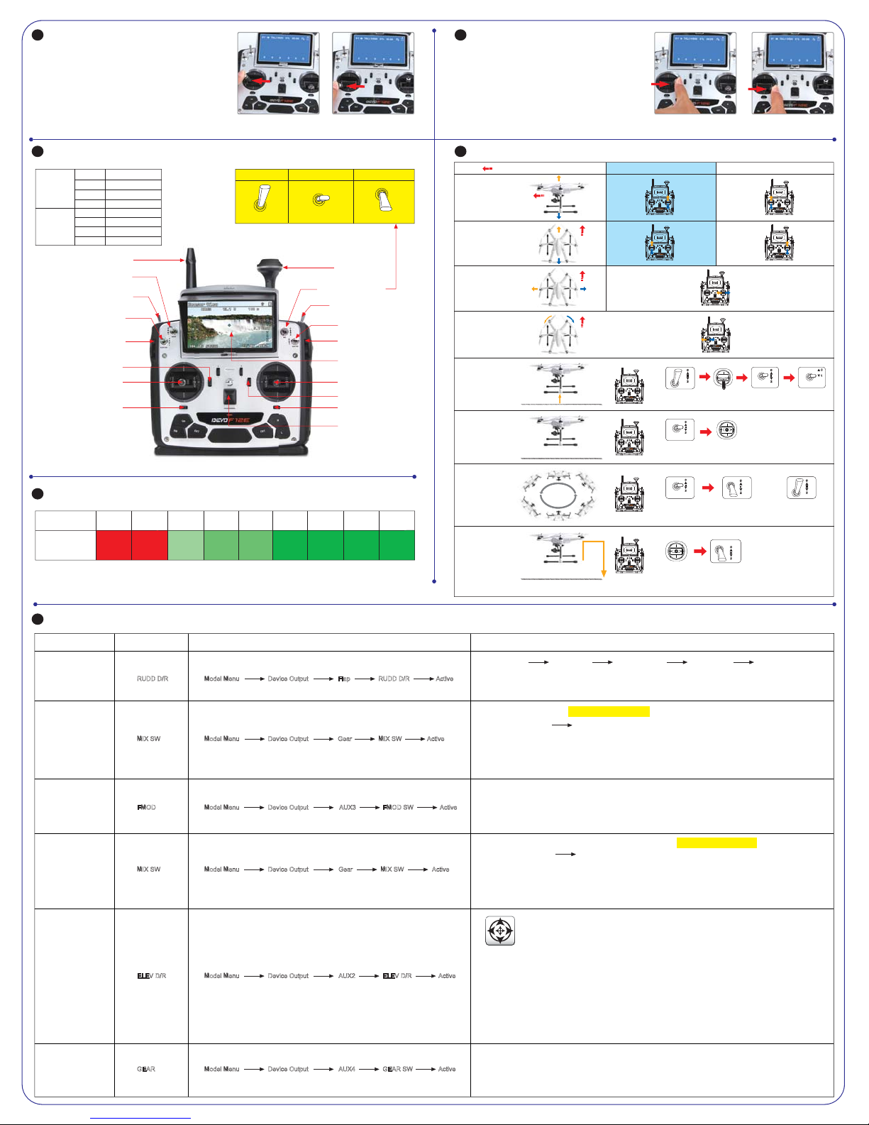
DEVO F12E- quick guide to control functions
8
THRO/RUDD stick
Left stick
Mode 2
Right stick
Left trim
Right trim
Right stick
Left trim
Right trim
2.4G TX antenna
ELEV/AILE stick
THRO trim
ELEV trim
ELEV/RUDD stickLeft stick
THRO/AILE stick
ELEV trim
THRO trim
4
(Throttle stick
on the left)
Mode 1
(Throttle stick
on the right)
GEAR - Landing Gear Switch Retract
and Deploy landing gear
RUDD D/R - AUTO Take off switch
ELEV D/R - IOC control switch
Inteligent Orientation Control
AUX5 - Gimbal ROLL control
Left trim
4
Left stick
RUDD trim
(0) Manual Mode (1) GPS-hold Mode (2) Return TO Home
MIX Switch to “0” MIX Switch to “1” MIX Switch to “2”
You NEED to memorize these settings
Mode 2(throttle stick on the left)Mode 1(throttle stick on the right) Mode 2(throttle stick on the left)Mode 1(throttle stick on the right)
5.8G RX antenna
MIX(Control Mode Switch)
FMOD - Round flight mode
AILE D/R - CAMERA Start/Stop
AUX6 - Gimbal TILT control)
"
5 LCD Screen
Right stick
Right trim
AILE trim
Power switch
9
GPS indicator lights
GPS Satellites
The blue
LED status
IMPORTANT: For SAFE flight in GPS flight mode: the BLUE indicator light should at least “double” blink, (two blinks at a time)
It is highly recommended to wait for “triple blink” 8 statelites before starting the flight.
NEVER attempt to AUTO-START with less than “triple blinks”
<6 6 7 8 9 10 11 12 13
No
Blinking
Blinking
Blinking
Blinking
Blinking
Blinking
blinking
once
2 times
3 times
4 times
5 times
6 times
Blinking
7 times
Blinking
8 times
Motor Lock
7
Lock the motors by moving the throttle stick all the way down and the
rudder (YAW) stick all the way to the right.
The RED-GREEN LED light will go out when the motors are disarmed.
TEST: push the throttle stick up a little, the motors will not start when locked.
NOTICE:
* The motors are LOCKED by default after successful binding.
* Motors can NOT be unlocked or locked in GPS-hold mode.
if you land in GPS mode, move the “MIX” switch to position “0”
before locking the motors, make sure you wait until the TALI is safely
on the ground before changing the switch to “0” (manual)
While changing, make sure to keep the throttle DOWN to prevent motors start.
Operation Instruction
10
Model ( is the nose direction)
Mode 1 Mode 2
THROTTLE
Up/down
PITCH
Forward/backward
H500 nose move up/down
ROLL (lean)
Left / right
YAW (turn)
Left / right
AUTO Take Off
You should have
triple blink = 8sats
for this feature.
ARM/UNLOCK motors
in manual mode
GPS hold mode
You can fly in this mode simply
move the controls when you let
go of the control, the TALI will stop
NOTE: You must CENTER the
throttle stick for altitude hold
ROUND FLY mode
This mode is used for
making circles around
a object of interest.
RADIUS is set in the
F12E menu by adjusting
Position 2 value for AUX3
RETURN TO HOME
Activating this feature will casue
the TALI to climb to 15m at this
height it will fly to the starting
location and proceed to land.
Ground
Ground
Ground
MIX
MIX Switch
move throttle
to “0”
down
MIX
MIX
Throttle stick
return neutral
Move FMOD switch to “2”
The Round Fly will start
MIX
MIX switch
to “2” position
MIX switch
to “1” position
MIX switch
to “1” position
15m
Throttle stick
return neutral
MIX
MIX switch
to “1” position
DO NOT switch to manual before
landing it is safer to land in GPS
hold mode. swtich to manual
AFTER landing to lock motors
FMOD
You can stop RTH by switching to
GPS hold MAKE SURE the throttle
stick is set to 50% when switching.
NEVER switch to MANUAL from
RTH, this can cause a crash.
Move FMOD switch to “0”
The Round Fly will stop
RTH mode is activated AUTOMATICALLY by the FAILSAFE system in a emergency, you may not be able to interrupt a EMERGENCY RTH
RUDD D/R
RUDD D/R switch
to “1” position
FMOD
11
DEVO F12E Radio function setup and operation instructions
Function Switch
AUTO Take Off
GPS hold mode
Round Fly
Mode
Return TO
Home
Hyper IOC Mode
Extend/Retract of
Landing Gear
RUDD D/R
MIX SW
FMOD
MIX SW
ELEV D/R
GEAR
Model Menu Device Output Flap RUDD D/R Active
Model Menu Device Output Gear MIX SW Active
Model Menu Device Output AUX3 FMOD SW Active
Model Menu Device Output Gear MIX SW Active
Model Menu Device Output AUX2 ELEV D/R Active
Model Menu Device Output AUX4 GEAR SW Active
Transmitter setting Instructions
Place aircraft
on level ground
IMPORTANT:
ONLY use this function with BLUE TRIPLE blink = 8 or more satelites, AUTO take off with less satelites may result in a crash.
AFTER completing auto-take-off, you can take control by moving the throttle stick to 50%, then flip the RUDD D/R switch to “0” position.
“0” position: Manual mode
Unlock Motors
“1” position:GPS hold mode
MIX switch to “1” position
NEVER use this mode with less than 8 satelites locked, you should see BLUE TRIBLE BLINK.
BEFORE switching mode, always put the throttle stick to middle position ( 50% )
IF the GPS signal degrades, the H500 will automatically enter “Altitude hold mode” note in this mode it will drift, but will hold its altitude.
After flying 50% of the battery, do NOT switch from GPS mode to Manual, this may cause a sudden drop / crash.
You can land in GPS mode, after landing, skeep the throttle stick DOWN and switch to manual, then lock the motors.
Move throttle stick
to lowest position
Throttle stick return neutral
Set MIX switch
to “0” Position
“2” position: Return To Home
Set RUDD D/R switch
to “1” Position
“0” Position: OFF “1” Position: Not in use “2” Position: activate Round Fly
This mode require 8 satelites locked, you should see BLUE TRIBLE BLINK.
BEFORE activating the round-fly mode, you should be in “GPS hold mode” always put the throttle stick to middle position ( 50% )
The default roundfly radius is 5 meters (15 feet), You can change the Round Fly radius by editing the AUX 3 EPA (End Point Adjustment)
on the F12E transmitter, for details on editing EPA settings, see the F12e instruction manual.
“0” position: Manual mode
Throttle stick return neutral
The Return To Home mode, only work when you have a solid GPS lock, it is recommend to avoid flying if GPS lock is missing.
After engaging Return to Home mode, lave the throttle stick at 50% (centered) do not touch any switches on the F12E radio.
You can REGAIN control of the H500, make sure the throttle is centered, then flip the MIX switch to “1” position.
in a emergency like loss of control link between the F12e and the H500, the Failsafe system will automatically start RTH,
you may not be able to interupt a emergency RTH, simply let the aircraft continue until it lands.
IOC or Intelligent Orientation Control mode
Means the aircraft’s flight direction is only relative to the orignal take-off point (where you armed the motors)
REGARDLESS of the actual aircraft headding, with this mode you can fly past something and pan the aircraft
to frame your shot, without having to worry what direction the aircraft is facing.
ELEV D/R switch “0” position: IOC OFF “1” position: IOC ON
The IOC mode require a strong GPS lock, you should have trible blinks on the blue GPS indicator light.
IOC is inactive if the H500 is less than 10 meter (30 feet) from the original take-off position. (point where you armed the motors)
Fly the H500 manually to past 10 meters using the GPS mode, activate the IOC mode when you are past 10meters, the H500
will now fly IOC until you change mode, you can pan freely for video shots, when you push the stick right or left, the H500 will
move sideways relative to the original take-off position. Pushing the pitch stick up will push the H500 away from you, bulling the
stick back, bring the H500 back to the starting point.
When flying in IOC mode, you can make the H500 retun home by simply puling the PITCH stick down.
WARNING: The IOC turns off when the aircraft get closer than 10meters to the take off point, be prepared for this, as the system
will switch back to GPS hold mode at that point. this switch can cause confusion if the pilot are not prepared.
GEAR Switch: “0” Position: Extend landing Gear “1” Position: Retract landing Gear
NOTE: REMEMBER your landing gear, it is easy to forget the landing-gear when flying FPV. its not a good idea to land on your
camera. When activating the RTH (Return To Home) system, either by the pilot of by the failsafe system.
The TALI H500 will automatically extend the landing gear to protect your camera and make sure the H500 land safely.
You can not change the landing gear after the H500 have automatically extended for landing. you must land and lock / unlock motors.
“1” position:GPS hold mode
MIX switch to “2” position
“2” position: Return To Home
 Loading...