

Page 1
Main Controller: FCS-X4
SCDutX4
• Auto Take off
• Object Round fly mode
• Hyper [ÓC mode
• GPS telemetry
• Altitude hold mode
• One key ReturnToHome
• Retractable Landing Gear
• 5.8G video down link
Match with DEVO F12E Radio
Quick Start Guide and Systems Flowchart
M1
5
'"JC?
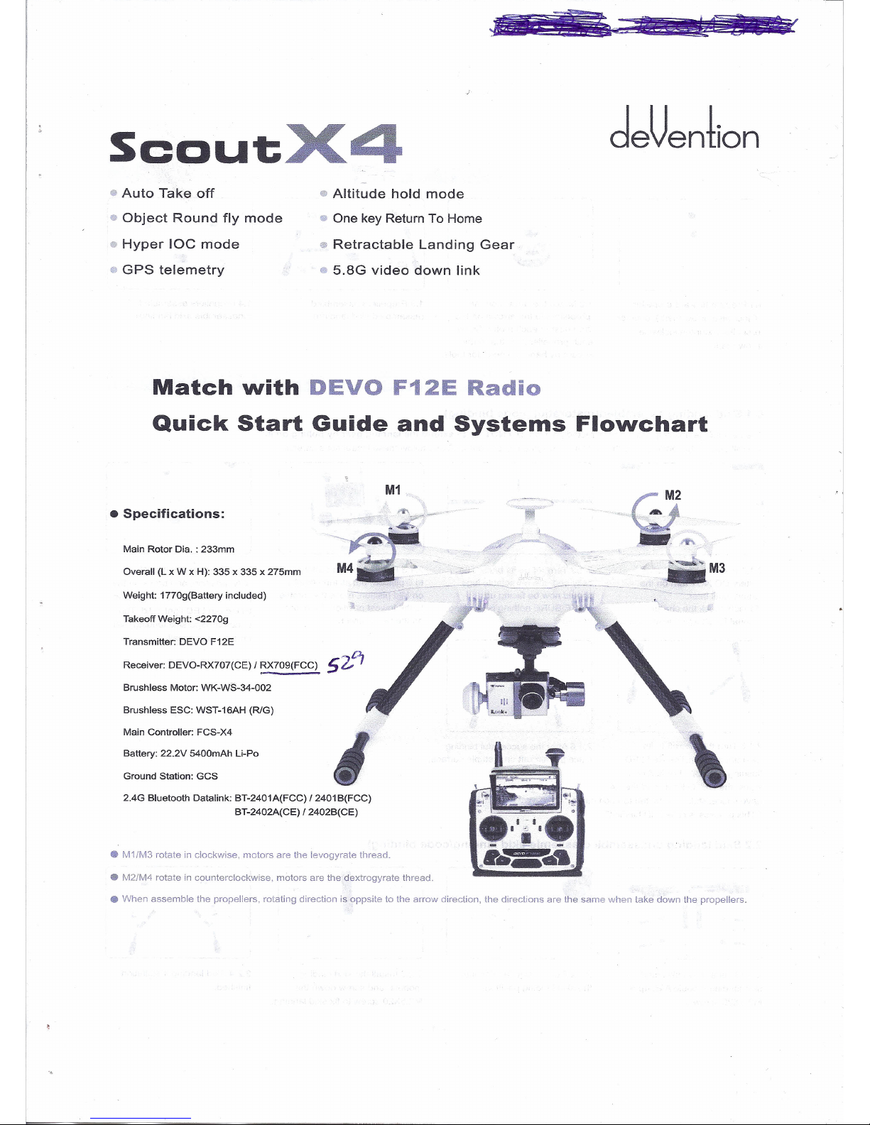
Receiver: DEVO-RX707(CE) / RX709(FCC)
v
• Specifications:
Main Rotor Dia. : 233mm
Overall (L x W x H): 335 x 335 x 275mm
Weight: 1770g(Battery included)
Takeoff Weight: <2270g
Transmitter: DEVO F12E
Brushless Motor: WK-WS-34-002
Brushless ESC: WST-16AH (RlG)
Battery: 22.2V 5400mAh Li-Po
Ground Station: GCS
2.4G Bluetooth Datalink: BT-2401A(FCC) / 2401 B(FCC)
BT-2402A(CE) /2402B(CE)
• M1/M3 rolate in clockwise, motors are lhe levogyrale lhread.
• M2/M4 rotate in counlerclockwise, motors are the dexlrogyrate Ihread.
• When assemble lhe propellers, rotating direction is oppsite to lhe arrow direction, lhe direclions are lhe same when take down the propellers.
Page 2
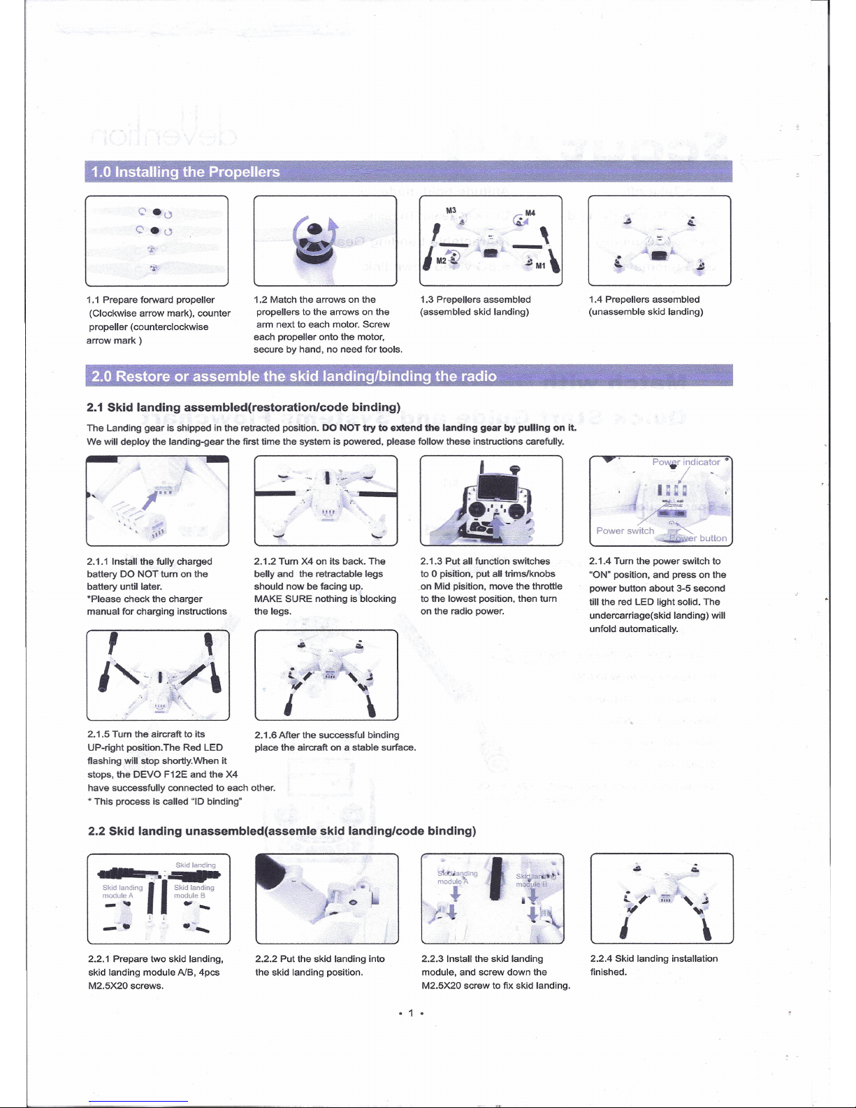
1.0 Installing the Propellers .
2.0 Restore or assemble the skid landing/binding the radio
1.1 Prepare forward propeller
(Clockwise arrow mark), counter
propeller (counterclockwise
arrow mark)
1.2 Malch lhe arrows on lhe
propellers10lhe arrows on lhe
arm next10each molor. Screw
each propeller onto lhe motor,
secure by hand, no need for tools.
2.1 Skid landing assembled(restoration/code binding)
M3
M4
,
:!:.
,;
'"
,
1::1F
•
-:-\
•• M1
1.3 Prepellers assembled
(assembled skid landing)
The Landing gear is shipped in lhe retracted position. DO NOT try to extend the landing gearbypulling on it.
We will deploy lhe landing-gear the first time the system is powered, please follow these instructions carefully.
2.1.1 Install lhe fully charged
battery DO NOT tum on lhe
battery until later.
'Please check lhe charger
manual for charging instructions
,
,
1"1:,"/\
.•.
,
2.1.2 Tum X4 on its back. The
belly and lhe retractable legs
should now be facing up.
MAKE SURE nothing is blocking
the legs.
~
~
c
,
tr.
~
j
."
~
l
\
2.1.5 Turn lhe aircraft10its
UP-righl position.The Red LEO
flashing will stop shortly.When il
stops, the DEVO F12E and the X4
have successfully connected to each other .
• This process is called
"10
binding"
2.1.6 After the successful binding
place lhe aircraft on a slable surface.
2.1.3 Put ali function switches
to O pisition, put ali trims/knobs
.on Mid pisition, move the throttle
to the lowest position, then tum
on lhe radio power.
2.2 Skid landing unassembled(assemle skid landing/code binding)
r
Skid landing
';
--.
g
m::~:;{ing
Skid landing II
Skid landing
" ••I
'"
module A
module B
_
..
~-
O
J--l
.'.
!
-
--.
.-
•...
2.2.1 Prepare two skid landing,
skid landing module AlB, 4pcs
M2.5X20 screws.
2.2.2 Put lhe skid landing into
the skid landing position.
2.2.3 Install the skid landing
module, and screw down the
M2.5X20 screw to fix skid landing.
• 1 •
"
.'
-
1.4 Prepellers assembled
(unassemble skid landing)
POWjr indicator •
I -
laa
Power switch .<.~
r button
2.1.4 Turn the power switch to
"ON" position, and press on the
power button about 3-5 second
till the red LEO light solid. The
undercarriage(skid landing) will
unfold automatically.
i ,-
ifil
i
'
2.2.4 Skid landing installation
finished.
Page 3

Red~
Power button,
:/
=-
Power swít h
Da f a _ ..
Power indicator
a aa a
2.2.7 Red LED f1ashing till to go out
means the code binding finished.
2.2.5 Put ali function switches
to O pisition, put ali lrims/knobs
on Mid pisition, move the throttle
to the lowest position, then turn
on the radio power.
2.2.6 Put the aircraft on the
horizontal position, slide the
power-switch to the ON position,
then press on the power button for
about 3-5 seconds, until the green
power indicator lights up.
•
•
•
IMPORTANT: Make sure ali TRIMs are in the center position, the trim value should be "O", and that the motors are locked.
The aircraft should NOT be f1ashing RED. By default, the motors will automatically be locked after the ID binding processo
For more details aboul locking and unlocking
motors,
see
points6&
7.
3.3 CLOCKWISE rotation. Rotáte
the aircraft around the roll axis rotate
smaothly in 90 deg increments.
Pausing 1 second for each 90 deg.
(O/ 90 / 1801270 / 360)
3.4 HORISONTAL rotation. Rotate
the aircraft araund the YAW axis
ratate smaothly in 90 deg increments.
Pausing 1 second for each 90 deg.
(O /90 /180 /270 /360)
3.1 Enter the calibration mode
Do this by moving both sticks
DOWN and to the middle position
at the same time. The aircraft will
start a blinking fast RED.
3.2 FORWARD rotation. Rotate
tilting the aircraft forward rotate
smoothly in 90 deg increments.
Pausing 1 second for each 90
deg.(O /90 /180 /270 /360)
• IMPORTANT: The first couple of flights, you may expereince the
aircraft drifting,
This is normal, please continue to fly the aircraft manually, while the
system inprave lhe calibration, after 5-10 minutes land, lock lhe motors,
this will save the improved settings.
Notice: The slight drifting may continue for a couple of batteries, you
will notice significant improvement in the GPShold & stability
after 4-5 batteries.
Nolice: Always perform lhe calibration away from eletric fields and
metal surfaces.
Trivia: Different brands have different calibration processes, lhe
process is lypically refered to as "lhe Calibralion Dance".
"
-,
'
..JI
"
\
-
.-..
-,
'--
,.
"
I
Ground
,
.,.,
~-
~"-,,.,
....
_,-
-,-
3.5 NOSE DOWN rotation. Rotate
the aircraft facing the nose down.
rotate smoothly in 90 deg increments.
Pausing 1 second for each 90 deg.
(O/90 /180 1270 /360)
3.6 Place the aircraft in normal
position The rapid RED blinking will
stop This indicate that the calibration
is finished Disconnect lhe battery to
save the settings.
4.0 G-3D 3-axis brushless Gimbal installation
IMPORTANT: REMOVE the battery from the X4 while you install the gimbal
The gimbal is a high-performance eletromechanical design and should be handled with great care. AVOID using force when installing.
4.4 Connect the 9pin white data
cable to the "complex data port"
on the bottom of the X4, then
connect the cable to the back of
the G-3D gimbaL
4.1 Prepare the G-3D gimbal,
M3x12 screw, spring.
4.2 Slide the gimbal unto the quik
mount rail, the gimbal shouldslide
from the front of the aircraft towards
the rear, gently moveitas far back
as possible.
4.3 Install the springloaded
M3x12mm "finger screw" at the
front of the gimbal, this will
secure the gimbaL
• 2 •
Page 4
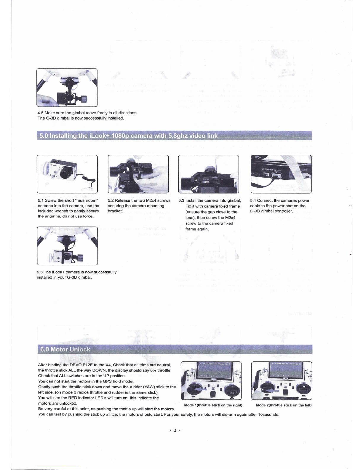
After binding lhe DEVO F12E 10 lhe X4, Check that ali lrims are neulral,
lhe Ihrottle stíck ALL lhe way DOWN. lhe display shoulo say 0% Ihrottle
Check thalALL swilches are in lhe UP posítion.
Vou can not start the motors in the GPS hold mode.
Gently push lhe Ihrottle stick down and move lhe rudder (YAW) stick to the
left side. (on mode 2 radios throttle and rudder is the same stick)
Vou will see lhe RED índicator LED's will turn on, this indicate the
motors are unlocked,
Se very careful at this point, as pushíng lhe Ihottle up will start lhe molors.
Vou can test by pushing lhe stick up a little, lhe motors should start, For your safely, lhe rnotors will dis-arm again afler 10seconds .
4.5 Make sure lhe gimbal move freely in ali directions.
The G-3D gímbal is now successfully installed.
5.1 Screw lhe short "mushroom"
antenna ínto lhe camera, use the
included wrench 10 genlly secure
lhe antenna, do not use force.
5.2 Release the two M2x4 screws
securing the camera mounting
bracket.
5.5 The iLook+ camera is now successfully
installed in your G-3D gimbal.
5.3 tnstall the camera ínto gimbal,
Fixitwíth camera fixed frame
(ensure lhe gap close 10 lhe
lens), Ihen screw the M2x4
screw 10 lhe camera fixed
trame again.
Mode 1(lhrottle stick on lhe right)
• 3 •
5.4 Connecl the cameras power
cable 10 the power port on lhe
G-3D gimbal conlroller.
Mode2(lhrottle slick on lhe lefl)
Page 5
leftstick THRO/RUOOstick
Rightstick ELEV/AllE stick
Lefttrim
THROtrim
Righttrim
ElEVtrim
Leftstick ElEV/RUOO stick
Rightstick THRO/AILE stick
leftlrim
ElEVtrim
Righttrim
THROtrim
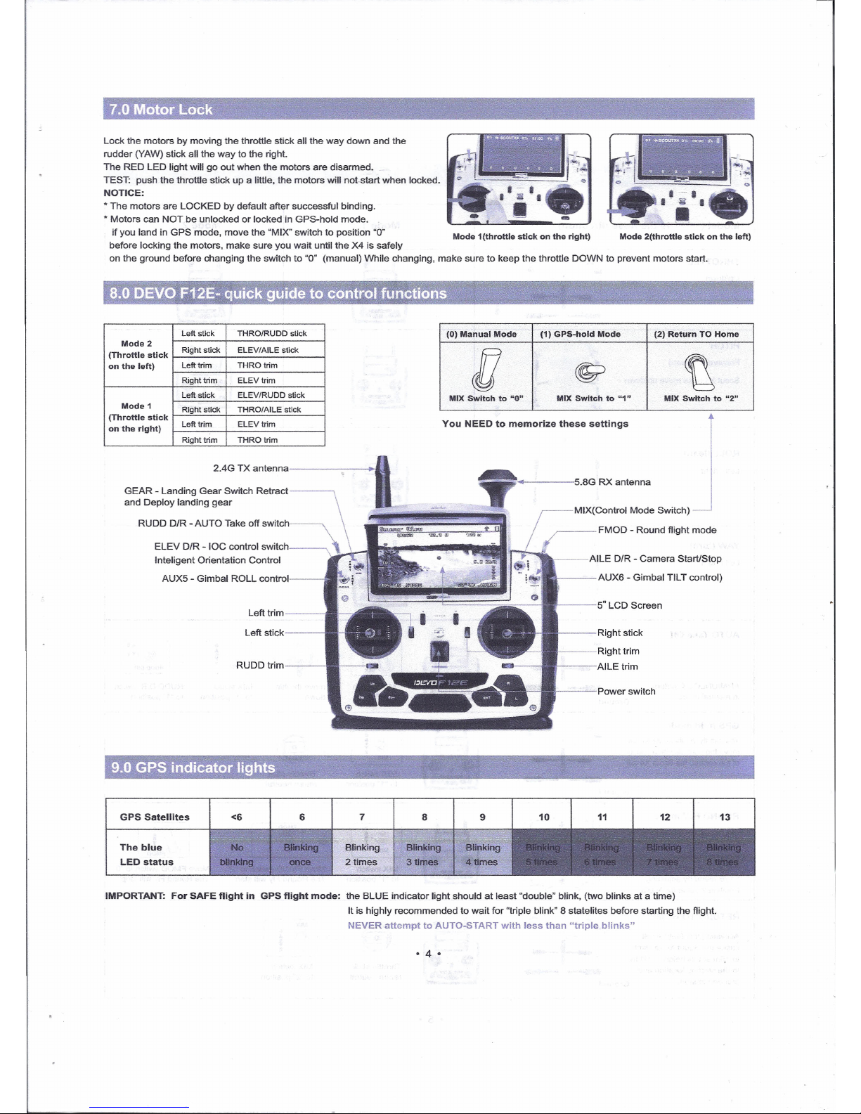
2.4G TX antenna
•
IJ
MIX Swltch to "1" MIX Swltch to "2"
7.0 Motor
;
Lock the motors
rudder (YAW) sti
The RED LED li
.
TEST: push the
NOTICE:
• The motors are
• Motors can NO
if you land in
before locking t
on the ground
'~,- ~ '-~-"'i ~~.~
'!-
8.0 DEVO
Mode2
(Throttle stlck
on the left)
Mode 1
(Throttle stick
on the rlght)
GEAR - Lan
and Deploy
RUDDD
ELE
Inteli
AU
.'
,
9.0GPSi
GPS Satelli
The blue
LED status
IMPORTANT: F
.
Lock
by moving the throttle stick ali the way down and lhe
ck ali the way to lhe righl.
ght will 90 out when lhe rnotors are disarmed .
throttle stick up a little, the motors will not-start when locked.
LOCKED by default after successful binding .
T be unlocked or locked in GPS-hold mode.
GPS mode, move lhe "MIX" switch to position "O"
he motors, make sure you wail until lhe X4 is safely
before changing the switch to "O" (manual) While changing, make sure to keep the throttle DOWN to prevent motors start.
Mode 1(throttle stick on the right) Mode 2(throttle stick on the left)
(O)Manual Mode (1) GPS-hold Mode (2) Return TO Home
MIX Swltch to ·0"
ding Gear Switch Relract~
landing gear
IR -
AUTO Take off switch
V D/R -IOC control sWitch~
gent Orientation Control
X5 - Gimbal ROLL control
MIX(Control Mode Switch)
Vou NEED to memorize these settlngs
Left trim
~==~...
----5.8G RX antenna
AILE
D/R -
Camera StartlStop
AUX6 - Gimbal TILT control)
5" LCD Screen
Left stick
Right stick
Righttrim
---AILE trim
RUDD trim---
----Power switch
8
tes <6
6
7
Blinking
3 times
Blinking
2 times
or SAFE flight in GPS flight mode: lhe BLUE indicator lighl should at least "double" blink, (two blinks at a time)
It is highly recommended to wait for "triple blink" 8 statelites before starting the ftight.
NEVER attempt to AUTO-START with less than "triple blinks"
• 4 •
Page 6

Model (
+-11I
is the nose direction)
THROTTLE
Up/down
,-
;j
-=1~-
~ I
~
I
~
I~-
_:_-
. _;A.
o
t '"
"'.-..d"~.1O:
,
;,~.
,
I
r~'1
I
r~"
!....~.
'····::1
__ J .••••
t· ,.
j
o
_;A .
.6:";;"' •.
.'"
•••
t
"
"
~.
, Ji'-:"""
__ ~l·~ __
~
-
1
.r,
-
t,· ~
8
;,. \!.
-<""~
,
";-":.' -.
,
t.:~.
•••••../'I ~.\.•••••
t
j
l~"··
.'"
.__ ;A,
.•••• 111
PITCH
Forward/backward
Scoul X4 nose move up/down
ROLL(lean)
Left/ righl
YAW(turn)
Left/ righl
AUTO Take Off
You should have
Iriple blink=8sals
for Ihis teature.
ARM/UNLOCK rnotors
in manual mode
GPS hold mode
You can f1y in Ihis mode simply
move lhe contrais when you lei
of lhe
control,
lhe
scout
X4 will
NOTE: You musl CENTER lhe
Ihroltle stick for allitude hold
ROUND FLY mode
This
mode is used for
making circles around.
a objeel of ínterest.
RADIUS is
set
in lhe
F12E menu byadjusling
Posilion 2 value for AUX3
RETURN TO HOME
Activating Ihis feature will
casue lhe Scoul X410elimb
10
15m aI Ihis heighl il will f1y
10
lhe slarting localion and
proceed10Iand,
_.:-
Ground
'j:. ~,
i:i
-i:a,
$~~"
-;-
Ground
...i-/-t..-~.;.-\-\~~:,,~
'f';~,.,.,~~
'•.,:r'll "
,í' {
,\ \ J ~'
'1>•• ~ '----""
~.i".
'-1,: "
l/'
...!-\, ~
':f
4
.""!-,I __
.;. . .' ;;C'
~.:t~"'
_:-
Ground
:.'
'''''~."'
_ t.~._ ...
4--=-"'a
:·~I'!.
•••••••
/- ..•..-!a
.-~~:
•••••••
!-"*-'a
a ..
Y'
~\~__ ·_r~~~
•••••••
- !li _
.e.-:-"'
a
Mode 1 Mode2
MIXSwilCh
10 "O"
move throttle
down
MIXswilch
10
"1" posilion
RUDD D/R switch
10
"1" posilion
[~!
j •• ~
DO NOT switch to manual before
landingitis
safer10land in GPS
hold mode. swtich10manual
AFTER landing10lock motors
MIXswitch
10
"1" posilion
Throttle
stick
relum neulral
[~! )
Mil<
••
MIXswilch
10 "1"
position
Move FMOD swilch10"2"
The Round Fly will start
Move FMOD switeh
10 "O"
The Round Fly will slop
~
.•
~
You can stop RTHbyswitching to
GPS hold MAKE SURE lhe Ihrottle
stick is set to 50% when switching,
NEVER swilch10MANUAL from
RTH, this can cause a crash.
Throttle stick
return neutral
MIXswitch
10
"2" position
• 5 •
Page 7

• 6 •
~,!!:~~<:r.;"F..:;;tt;r;.-!',':hi!l"'ll"J·""'l~
'~,"''''\!OM-~'''<'l.''J\'''':t'~~>:'~'''~Th':;!_',i\\Wil.~'~_••
'~tt:;.t",,<,''{tlf,J1'~"~~ ~
11.0 DEVO F12E Radio function
s~tup,andoper~tiot:lJ!nstr~ctions::'." ':
<
-< ',,;:
Function Switch
Transmitter setting
Instructions
ModeLMenu
Place aircraft on levei ground --- Unlock Molors ___
•
Move Ihrottle stíck ___
Sei MIX swilch
Devicé Output
to lowesl posilion
10 "O"
Posilion---
•
SeI RUDD D/R switch to "1" Position
AUTO
RUDD D/R
Flap
Take Off
IMPORTANT:
•
ONlY use Ihis function with BlUE TRIPlE blink = 8 or more
RUDD D/R
satelites, AUTO take off wilh less salelites may result in a crash.
~
AFTER completing auto-take-off, you can take control by moving
the Ihrottle stiek1050%, then ftip the RUDD D/R swileh to
"O"
position.
Active
"O"
position: Manual mode
"1" position: GPS hold mode
Model Menu
"2" position: Return To Home
•
MIX switeh to "1" position
----+ Throttle stick return neutral
Device Output
NEVER use this mode with less than 8 salelites loeked, you should
•
see BlUE TRIPlE BLlNK,
GPS hold
Gear
Before switehing mode, always put lhe throttle stiek to middle
mode
MIXSW
position ( 50% ).
•
IF the GPS signal degrades, the X4 will automatieally enter "Altitude
!
hold rnode" note in Ihis mode it will drift, but will hold its altitude.
MIXSW
~
After flying 50% of the battery, do NOT switeh from GPS mode to
Manual, Ihis may cause a sudden drop / crash,
Active
Vou ean land in GPS mode, after landing, keep lhe throttle stiek
DOWN and switeh to manual, Ihen loek the motors,
"O"
Position: OFF
"1" Position: Not in use
Model Menu
"2" Position: aetivate Round Fly
•
This mode require 8 salelites loeked, you should see
Device Output
BlUE TRIPlE BLlNK.
•
Before activating lhe round-fly mode, you should be in "GPS hold
mode" always put the Ihrottle stiek10middle posilion ( 50% )
Round Fly
FMOD
AUX3
The default roundfly radius is 5 meters (15 feet), Vou can ehange lhe
Mode
•
Round Fly radius by editing lhe AUX 3 EPA (End Point Adjustmenl)
on lhe F12E transmitter, for delails on editing EPA settings, see the
FMODSW
F12E instruetion manual.
~
After having ehanged the setting, you should lurn FMOD switeh to
"O"
Active
posilion to save the data, then relum10"2" posilion10read lhe new
Roundly radius.
Model Menu
"O"
position: Manual mode
"1" position: GPS hold mode
•
"2" position: Return To Home
Device Output
Throttle stick relum neutral ----+ MIX switeh to "2" position
•
The Relum To Home mode, only work when you have a solid GPS
loek, it is recommend to avoid flying if GPS loek is missing.
Return TO
MIXSW
Gear
After engaging Return to Home mode, lave lhe throttle sliek at
Home
•
50% (eenlered) do not toueh any switehes on the F12E radio.
Vou ean REGAIN control ofthe Scout X4, make sure lhe throttle is
MIXSW
eentered, then ftip the MIX swileh to "1" posilion. in a emergeney like
~
loss of controllink between lhe F12e and lhe Seout X4, lhe Failsafe
syslem will aulomalically start RTH, you may not be able10interupl
Active
a emergeney RTH, simply lei lhe aireraft conlinue unlil il lands .
Page 8

Model 1(ELEV
(THROtrim)
Transmitter
-
Function 5witch
setting
Instructions
~
IOC or Intelligenl Orientalion Control mode Means lhe aircraft's flighl direclion is
only relalive10lhe orignal take-olf poinl (where you armed lhe molors).
REGARDLESS of lhe actual aircraft headding, wilh Ihis mode you can fly past
Model Menu
somelhing and pan lhe aircraft10frame your shot, wilhout having to worry what
direction lhe aircraft is facing.
+
ELEV D/R switch "O" position:
ioc
OFF "1" position:
ioc
ON
Device Output
The loe mode require a slrong GPS lock, you should have Irible blinks on lhe blue
+
GPS indiealor light.
HyperlOC
AUX2
loe is inaelive if lhe Seoul X4 is less than 10 meter (30 feel) from lhe original take-off
Mode
ELEV D/R
position. (poinl where you armed lhe rnotors)
+
FIy lhe Seout X4 manually to past 10 meters using lhe GPS mode, aelivale lhe loe mode
ELEV D/R
when you are past 10melers, lhe Seoul X4 will now fly loe unlil you ehange mode, you ean
pan freely for video shots, when you push lhe stick right or left, the Seout X4 will move
+
sideways relative to the original lake-off position. Pushing lhe piteh sliek up will push the
Seout X4 away from you, bulling the stiek baek, bring lhe Scoul X4 baek 10 lhe slarting point.
Active
When flying in loe mode, you can make lhe Scoul X4 relun home by simply puling the
PITCH stiek down.
WARNING: The loe turns off when lhe aireraft get eloser than 1Omelers to lhe take off
poinl, be prepared for this, as the system will switch back to GPS hold mode aI that
poinl. this switch can cause confusion if lhe pilot are not prepared.
Model Menu
.
+
. "O" Posilion: Extend landing Gear
Oevice Output
"1" Position: Retrael landing Gear
Extend/
+
NOTE: REMEMBER your landing gear, it is easy to forget the landing-gear when f1ying
Retract of
AUX4
FPV. its not a good idea to land on your eamera. When aetivating the RTH (Return To
GEAR
Home) system, either by the pilot of by the failsafe syslem.
Landing
+
The Seout X4 will automalieally extend the landing gear 10 protect your camera and
Gear
make sure the Seout X4 land safely.
GEARSW
Vou can not ehange the landing gear after lhe Seout X4 have automalically exlended for
+
landing. you rnust land and lock / unloek motors.
Active
12.1 Boot Screen(Main interface)
Model No
Model name Throttle percenlage value
Timer display
display
I
I
Transmi
01
~
Model01 0% 00:00
~
~
==-0
y
O
~
O
O
~
O
trim)
I
I
Model1
trim)
Model
Left Irim display Righl Irim display
ssion power display
Model type
Battery capaeity display
Rudder Irim displa
Aileron Irim display
Model 2(THRO
2(ELEV Irim)
·7·
Page 9

Model Select
ENT
02~ Model 02
03~Model 03
04~ Model 04
05~ ModelOS
06~ Model 06
07~ Model 07
08~ Model 08
12.2 Model Select
Model Select
I
Main
I
ENT
I' I
UPIDN
I I
interface -- Maln Menu ENT' Model Menu
UP/DN
ENT
<I' 01*'Model 01
Press UP ar DN button to select the stored model NO.For example "Model 01",
press EXT to retum back "Model Menu" after finished.
12.3 Model Name 12.4 Type Select
I I
UP/DN
I I
ENT
Model Menu • Model Name
j
---'---."
Model Name \/ ~
I I
UP/DN
I
Model Menu • Type Select
I.
ENT
j
.e,
SCOUTX4
Helicopter
Type Select
No. 01
Name
Glider
Press UP ar DN button to select the characters which
need to be changed, Named model as "SCOUTX4".
Press EXT to retum "Model Menu".
Select the model type by R ar L button, and confirmed with ENT,
once finished will retum to "Model Menu" automatically
12.5 Wing Type
I I
UP/DN
I
Model
Menu.
Wlog
TV,.
I~
------::--,
WingType
Wing Type
V-Tail
Dual Channels
Mate
Trim
Twin Engine
Trim
Inhibit
Inhibit
Inhibit
Inhibit
Inhibit
Inhibit
Press R ar L to select "Normal", then press EXT to retum "Model Menu".
12.6 Device Output
Device Output
.e,~
Device Output
'Ô'~
.blf$W.
GM4iM
Gear
AUX4
Active Active
Flap
RUDD D/R AUX5 AUX5 KB
Active
Active
AUX2 ELEVD/R AUX6 AUX6 KB
Active Active
AUX3
FMODSW AUX7 AILE D/R
Active Active
·8·
Press EXT to retum back "Model Menu" after finished.
I
Model MenuIUP/DN·l Oevice outputl __E_N_T_
Page 10

12.7 Sensor Setting
Voltage
Temperature
GPS Setting
Sensor Setting
I I
UP/DN
Model Menu • Sensor Setting
Press R or L to seleet "Active".
(1) Voltage Setting
Press UP orDNto select Voltage in the Sensor Setting. Press ENT to enter Voltage interface.
ENT
Status
-4'$!§!.
No Signal
Sensor Submenu
Inhibit
Voltage
Inhibit
Seout X4 default setting is 21.4V, please fly back the capte r when you gel a warning asap.
Internal:
VO
Internal shows the Radio battery voltage.
External: V1 Aetive
-liM
External: V2 Inhibit
Altitude Type
Speed Unit
Date Type
TimeZone
(2) GPS Reeeive Setting
Press UP or DN to seleet GPS setting on the Sensor Setting interfaee. then press ENT to enter GPS Setting interface.
GPS Setting
External shows the aireraft battery voltage.
.@$M
(2.2) Speed Unit setting:
Press R ar L to select Km/h ar Knote.
(2.1) Altitude Type setting:
Press R orLto seleetAbsolute or Relative.
Km/h
DD-MM-VY
UTC+08:00
(2.3) Date Type setting:
Press R or L to select DD-MM-YY\ MM-DD-YY\ VY-MM-DD.
(2.4) Time Zone:
Press R ar L to select Time Zone, then press EXT to return "Main Menu".
12.8 Reverse Switch
I I
UP/DN
Main Menu ---.
. . ENT
UP/DN
I . I
ENT . .
Function Menu ENT. Reverse SWltch -- The faetory default Settinqs Interfaee as piture.
Reverse Switeh
Elevator
Aileron
Throtlle
Rudder
Gear
Flap
AUX2
AUX3
{7~
Mb.!i..ijiM
Reverse Switeh
AUX4
.Ú.U"h'M
Normal
Normal
Normal
Normal
Normal
Normal
Normal
AUX5
AUX6
AUX7
Normal
Normal
Normal
Press EXT to return baek "Funetion Menu"
afler finished.
·9·
Page 11

12.9 Servo Travei Adjust
Travei Adjust
Elevator
"IImi.•
ENT
0100.0%
Aileron L100.0%
R100.0%
I
I
UP/ON
Function Menu • Travei Adjust
Throttle H100.0%
L100.0%
L100.0%
R100.0%
Rudder
Press UP or ON to select Flap channel. Press R or L to set as U150.0% and 0150.0%.
Press UP or ON to select AUX3 channel. press R or L to set +5.0%(5 means Roundly cruise flying
radius is 5 metre) and -100.0%. then press EXT to return Function Menu.
12.10 Senser View
I
Function Menu
I
UP/ON
I
Se",e' ~ew
I E:T
I
Sensor View
I
ri -----
Battery volume display
I
Timer display--- --;:00:53
~
Travei Adjust
1t~~
Gear +100.0%
-100.0%
Flap
Im.~.!.•
0150.0%
AUX2
+100.0%
-100.0%
AUX3
+5.0%
-100.0%
Travei Adjust
1t~
AUX4
.[.!tI.•
-100.0%
AUX5 +100.0%
-100.0%
AUX6 +100.0%
-100.0%
AUX7 +100.0%
-100.0%
1
OOm~1---
Horizontal distance
~ display
5. OKm/h* --
Move speed display
Longitude display·----j!.-104° 15.5123E 22° 06.0902N4---Latitude display
L- ~
12.1V
+
Altitude display----
.10m
Press R or L to select viewport display. When set the image as background. Information will be displayed on the image.
12.11 Video Setting
_U_P_I_D_N_I
Vídeo Settíng
I
Main Menu
I U:;N·I
System Menu
ENT
Status:
Press R or L to select "Active".
Channel: Press R or L to select suitable receiving video channel to iLook+ .
Background: Press R or L to selectActive. Real-time image could be set as background in Main Menu.
Press EXT to show fuI! screen image in Main Menu.
·10·
Video Setting
Status
Kmi@-e'
Channel
1/32
Background
Active
Page 12

12.12 Timer Setting
Stick Position Switch
Channel: Press R ar L to select "Throttle".
Higt
Off
I
Main Menu
I
U:~~N·I
Model Menu
UP/DN ENT
Stick Position Switch
Switch
Channel
Position
Switch: PressRarlto select "SPSO SW".
Throtlle
L94%
On
Position: Presslto set percentage(Suggest setting is
194%).
On setting: PressRarlto select "High" as rocker direction of on.
Move up and down of the throttle to check if the direction of the switch is set correctly. Then press EXT to retum "Main Menu".
I I UP/DN
I
I UP/DN
Main Menu ENT • Function Menu •
SPSO SW
Timer
L.
I-E-N-T------~I
Timer
Type
Switch
Type: Press R arlto select stopwatch ar countdown.
Switch: Press R arlto select "SPSO SW'.
Press EXT to retum back main interface after finished.
Usage: Toggle lhe throttle up to
194%
to start the time, toggle the throttle down to
L94%
to stop the time, press DN to reset,
01
+
Model01 0% 00:00
Tlme,~
o
o
o o o
o
·11 •
Page 13

<D
To roundly cruise flight mode
®
To check voltage(connect with power board)
@
Connect with fifth way brushless ESC
®
@
Used for data transmission-connect the PPM OUT
@
To hyperlOC
port of BT-2401 N2402A
Connect with forlh way brushless ESC
®
To one key to take off
@
Jumper porâ when regular receiver is
@)
Connect with third way brushless ESC
need, inseri random equipped bind plug pls.
@)
Control Mode Switch
@
To linkLED
@
Connect with second way
brushless ESC
®
To control Rudder
@
To link GPS module(red white blue black four color cable)
@
Connect with first way brushless ESC
®
To control Throttle
@
Connect wilh eighth way brushless ESC
@
Upgrade channel
(J)
To control Elevator
@
Connect with seventh way brushless ESC
@
Data communcation port
(forward & backward)
®
To control Aileron
@
Connect with sixth way brushless ESC
@
To link Compass
(Ieftward & rightward)
(red black double color cable)
I
Telemetry connector(connect with single white line)
I
DATA BUS: Used for data transmission-connect the PPM IN port of BT-2401N2402A
I
AUX3: Roundly cruise flight mode(no need to connect)
i----
-r-,
~AUX4: Connect the servo of landing skid-connect the PWM3 IN port of BT-2401N2402A
AUX7: Connect camera controller/Clear fix ID code(When c1ear fix ID cade is need, inseri random equipped bind plug pls).
Attention: DEVO RX707(CE) and DeVO RX709(FCC)have the same ports.
AUX1: One key to take off(no need to connect)
AUX2: Hyper IOC(no need to connect)
AUX5: Connect gimbal RolI singal cable-connect lhe PWM 2 IN por! of BT-2401N2402A
AUX6: Connect gimbal PIT singal cable-connect the PWM 1 IN por! of BT-2401N2402A
Page 14

PIT: Set up gimbal tilt angle(control angle range -135°- 90°). please refer to the mid-point
as starting point. proper adjust the knob in counterclockwise direction.
ROLL: Set up gimbal rolling angle(control angle range 45°- 45°). please refer to lhe
mid-poinl as startinq poínt, proper adjust the knob in counterclockwise direction.
,---- Shutler Button
Video/Photo Switch
16.1 Pictures iIIustration
16.2 Specifications
Anlenna
l
(1) Video
a. Video Resolution: 1920 x1080 Full HO
b. FPS: 30
c. Micro High Speed SO card: Max 64G
d. Imaging Sensor: 3.000.000 Pixels
//
Indicator(Red light)
Micro SD card slot
e. Video Formal: MOV
f. Photo: 4032x3024 Pixels
(2) 5.8G wireless
a. 5.8G wireless image transmission
b. FCC Output PowerS;200mW
c. CE Output Powers;25mW
d. CE Bind B section: 8 channels
I~. __
Channel cade swltch
".;
e. FCC Bind B section: 4 channels
16.3 iLook+(FCC/CE) camera transmitting channel selection
There are 8 different channels can be selected. You can choose lhe besl frequency channel according to the image quality as bellow:
Channel
1
2
3
4
5
6
7
8
Frequency
5866MHz 5847MHz
5828MHz 5809MHz 5790MHz 5771MHz 5752MHz 5733MHz
code
3
2
1
3
2 1
m
lààúl
[!TI]
3
2 1
[TI]
m
position
i
&1
&
g
i!
&ea
!
io~
!
i
!
!~i
8ft!
(off/on)
ON
ON ON
ON ON ON
ON
Note: Only transmitting channel 2. 4, 6, 8 are available for the iLookliLook+(FCC).
·13·
Page 15

16.4 Video and Photo user guide
Warm tips:
(1) Miero SO card must be inserted to the iLook+ eamera before eonneeting the power, and took off after disconnecting the power.
(Reeommend to use high speed SO card)
(2) Insert MICRO SO card, the camera is powered on, thered indicator light indicates the camera is initialized, the red light goes out indicates the
camera enters standby mode initialization is complete.
(3) Insert MICRO SO card, the camera is powered on, if the red indicator light blinks rapidly means formatting it is necessary.pls stir video/ photo
switch to •• position press shutter last for 5 sec.format after the completion of the proposed re-energized camera.
(1) Video instruction
(1.1) Radio Operation
Switch
Transmitter
Instructions
setting
Model Menu
(1) It's a must to turn the switch of iLook+ to." ••• position.
~
(2) Start video: lurn lhe AILE D/R swileh from "O' position 10"1" position, wail for 1-2 seconds, Ihen relurn
Device Output
10 "O' position, lhe camera will slart 10 video (lhe red indicalor keeps flash wilh an inlerval of 0.5 seeond).
~
The red indication of video status can be seen on lhe Iransmitter.
AILE D/R
AUX7
Stop video: lurn lhe AILE D/R swileh from "O" position 10"1" posilion, wail for 1-2 seeonds, then return
~
10 "O" posilion, lhe camera will stop video (lhe red indicalor lighls out), And lhe red indiealion of video
AILE D/R
status can not be seen on lhe Iransmitter.
~
Active
(3) Make sure Ihal lhe video recorded will nol be saved in lhe SO card if you haven'l finished
lhe 'slop video' operation.
(1.2) Manual Operation
Turn lhe Video/Pholo Swich 10 •• firsl please, press lhe shutter button once, iLook+ camera starts 10 Video(lhe Red indicalor flash for 0.5sec
interval); Press lhe shutter button again, iLook+ camera stops video(The Red indicator lighl out),
(2) Photo instruction
Please Turn the video/photo switch to
10,
Press the shutter button once, iLook camera WiII take a photo (The Red indieator blinks once then light
out), press the shutter button again, it will take another photo .
•
.
.
Slide the power switch to "ON" position when charging, press the power button for 3-5 seconds till the power indicator keeps on.
,<p •
Power butlon
~:=='-::~..-..-Power switch
III
t--Power
indicator
For details, please refer to iMAX 86 user manual.
·14·
Page 16

Te!.: (8620) 8491 5115 84915116
Fax.: (8620) 8491 5117
Email: heli@walkera.com
info@walkera.com
Add.: Taishi Industrial Park, Dongchong Town
nansha District, 511475 Guangzhou
Specifications,contents of parts and avsilability
are subject to change,Walkera is not responsible
for inadvert errors
(E~~':~
in this publication.
A
'f>!-~41
_ "cv
GV
Web:www.walkera.com
 Loading...