

www.walkera.com
QUICK START GUIDE
18th-OCT-2016
V1.0

-2-
4
3
7
8
8
9
6
9
13
16
16
16
17
18
12
13-14
5
6
6
1.0 Get to know your aircraft
2.0 Get to know your Remote Controller
3.0 Specifications
4.0 Attention before Flying
5.0 Charge the Battery
6.0 Prepare the Remote Controller
7.0 Prepare the aircraft
8.0 Ready to Fly
15
15
10-12
8.1 Starting the aircraft
8.2 GPS indicator lights
8.3 Motor Unlock / Lock
9.0 Operation Instruction
10.0 End Flying
11.0 Additional remarks
11.1 DEVO 7 Remote Controller Setting
11.2 TX5834(FCC)/TX5835(CE) Video transmitting channel selection
11.3 OSD interface information Introduction
11.4 Introduction for FCS-250 Main Flight Controller
11.5 Introduction for DEVO-RX717 receiver
11.6 Brushless ESC and Brushless Motor connection diagram
11.7 Compass Calibration
12.0 Instructions for GA005 balance charger
Contents
-3-
The RUNNER 250 body is created using CFP for outstanding crash survivability.
Modern industrial and modular design, improves the product performance and permit easy
maintainance and upgrades.
Advanced 5.8ghz live video and OSD system, for a unforgettable visual FPV experience.
Equip with dual GPS module, the RUNNER 250 advance can realize GPS hold mode, Circle Flight,
Hyper IOC and one key return to home.
1.0 Get to know your aircraft
ON
21
5. Counterclockwise motor
(dextrogyrate thread is clockwise)
6. Clockwise propeller
7. Counterclockwise propeller
8. GPS
9. SBUS/PPM connection port
10. 5V power output port
11. FCS-250 Main Controller
12. Battery: 11.1V 2200mAh 25C 3S Li-Po
13. Transmitter code switch
14. Mushroom antenna
15. DUAL reciever antennas
for best performance
* always extend before flying
16. Red LED light x2
17. Turn indicator light x4
18. OSD code switch:
Slide the code switch “1” to “ON” to start the OSD
1. Camera
2. Lighting Lamp x2
3. Landing gear x4
4. Clockwise motor (levogyrate thread
is counterclockwise)
* To avoid property loss and personal injury caused by wrong operation, please read the manual carefully before flying.
Quick Start Guide
-4-
DEVO-7
GPS-hold ModeManual Mode
MIX Switch to “0” MIX Switch to “1” MIX Switch to “2”
Return TO Home
2.0 Get to know your Remote Controller
Equipped with the Manual Mode / GPS hold mode / one key return to home / Circle Flight / Hyper IOC,
camera controlling switches, the RUNNER 250 is easier to control.
(You can select suitable flight mode according to your flying skill.)
1. HOLD TRN switch
2. GEAR switch
3. AUX2 control
4. Left stick
5. Left trim
6. RUDD trim
7. UP+ key
8. DN- key
9. EXT key
10. FMOD - Flight Mode Switch
11. MIX - Control Mode Switch
12. ELEV/AILE/RUDD D/R Switch
13. Right stick
14. Right trim
15. Power switch
16. AILE trim
17. R+ key
18. L- key
19. ENT key
FMOD(FMD) Switch to “1”
Position: Hyper IOC Mode
FMOD(FMD) Switch to “2”
Position: Circle Flight Mode
Take the "MODE 2 (Throttle stick on the left)" as an example. The left stick controls the aircraft's altitude and
heading, while the right stick controls its forward, backward, left and right movements.
Left Stick Right Stick
Forward
Backward
Left Right
Up
Down
Turn
Left
Turn
Right
* 1) MODE 2 (Throttle stick on the left): Left stick- THRO / RUDD; Right stick - ELEV / AILE.
2) MODE 1 (Throttle stick on the right): Left stick- ELEV / RUDD; Right stick - THRO / AILE.
Quick Start Guide
When aircraft backward, the left/right turn indicator lights will be solid.
When aircraft lean left, the left turn indicator light will be solid.
When aircraft lean right, the right turn indicator light will be solid.
When aircraft turn left, the left turn indicator light will flash.
When aircraft turn right, the right turn indicator light will flash.
-5-
Frequency:
Output Power:
Current drain:
Power Supply:
Output Pulse:
2.4GHz DSSS
≤100mW
≤230mA(100mW)
5# Battery 8x1.5V or NiMH 8x1.2V 1600-2000mAh
1000-2000mS(1500Ms Neutral)
205mm
221mm
143mm
117mm
3.0 Specifications
Aircraft
Main Rotor Dia.:
Overall (L x W x H):
Weight:
Remote Controller:
Receiver:
Main Controller:
Transmitter:
Brushless Motor:
Brushless ESC:
Battery:
Flight Time:
Working Temperature:
143mm
221 x 205 x 117mm
464g (Battery excluded)
DEVO 7
DEVO-RX717
FCS-250
TX5834(FCC)/TX5835(CE) (OSD included)
WK-WS-28-014A(CW/CCW)
F210 ESC
11.1V 2200mAh 25C 3S LiPo
10~12mins
-10℃~ +40℃
Camera(800TVL)
Horizontal Resolution:
System Commitee:
Video Out:
Power Input:
800TVL
PAL/NTSC
1.0Vp-p/75Ω
DC 12V
DEVO 7 Remote Controller
5.8G wireless image transmission
TX5834(FCC) Bind B section: 8 channels
TX5835(CE) B section: 8 channels
TX5834(FCC) output power ≤200mW
TX5835(CE) output power ≤25mW
TX5834(FCC) / TX5835(CE) Transmitter
Quick Start Guide
-6-
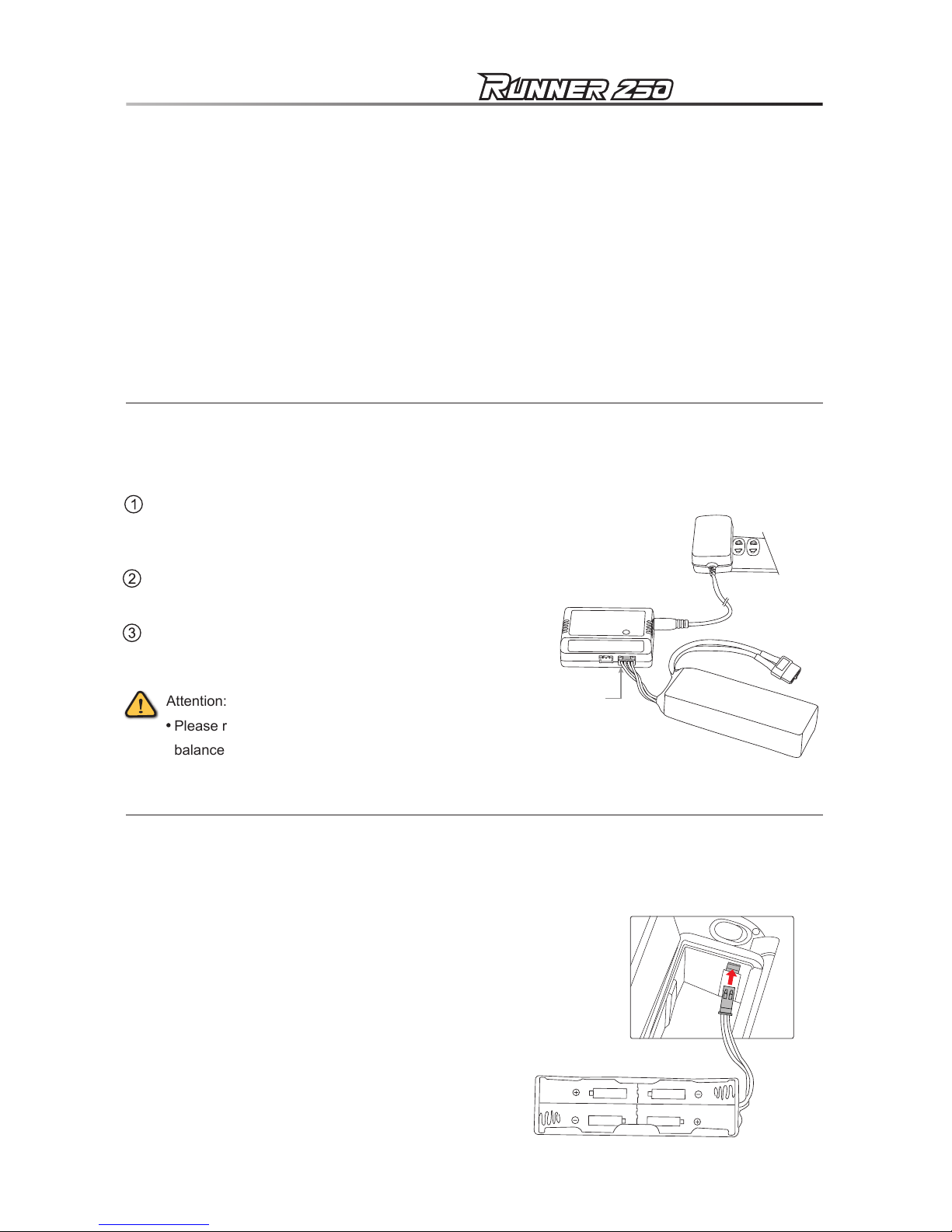
Attention:
Please refer to Page 18 for details of GA005
balance charger.
Power Adapter
GA005 charger
11.1V 2200mAh
LiPo battery
3 Cell DC 11.1V
Battery box
1) The RUNNER 250 is recomended for pilots, 14 years or older, with RC hobby experience.
2)
Only fly the RUNNER 250 in dry weather, with low wind, please do not fly in rain or heavy foggy conditions.
3) Always choose large open fields for flying. Check local LAW and ordinances for legal flying areas.
4) Always keep at least 10 feet distance to the aircraft when armed, to avoid injury from high-speed propellers
on the ground or while flying. Always disarm before handeling the aircraft.
5) Do not fly close to high-voltage power lines, cellphone towers, or radio towers, as these may disrupt
your control signal.
6) ALWAYS check local laws BEFORE flying. NEVER fly over crowds, concerts or sports stadiums.
4.0 Attention before Flying
5.0 Charge the Battery
Insert the power adapter(100~240V 50/60HZ), connect
the output end to the GA005 balance charger, the balance
charger is red LED at this time.
During charging, Red LED is continuously flashing. If
saturated, Red LED becomes solid green lighting.
Insert the battery charging terminal into 3 Cell DC 11.1V
charger socket.
6.0 Prepare the Remote Controller
Open the battery cover and remove the battery box. According
to the battery positive and negative polarity, install 8pcs 5#
batteries or 8pcs NiMH batteries with same volume.
Warning:
Battery polarities must be correctly installed.
When insert the plug of battery box into power
socket of remote controller, the fool-proofing
port must be inserted into fool-proofing port.
Quick Start Guide

-7-
7.0 Prepare the aircraft
Install 5.8G antenna
Firstly install 5.8G antenna onto the transmitter,
and tighten with open-end wrench.
Open-end
wrench
Install propellers
Fix the CW propeller( ) onto the CW motor
according to the direction of blue arrow, and fix the
CCW propeller( ) onto the CCW motor according
to the direction of orange arrow.
Tighten the propellers manually and make sure the
propeller is installed in proper way and fastened.
Attention:
Install prop by hand and tighten by holding
the motor with the included wrench.
You can also use the wrench to help remove
broken props in case of a crash.
Open-end
wrench
CW propeller
( )
CW propeller
( )
CCW propeller
( )
CCW propeller
( )
Front
Front
Battery installation
Put the battery and the Battery anti-slip mat into the
RUNNER 250, balance the gravity, keep the
head and
the tail parts aligned, then fasten the battery
with the
Velcro strap.
Battery anti-slip mat
Battery
Gravity center adjustment
Grab the RUNNER 250 by the COG line
(center ofgravity). See the illustration for the COG.
Adjust the battery forward-backwards until the quad
balances.
Gravity Center line
Quick Start Guide

-8-
8.1 Starting the aircraft
8.0 Ready to Fly
Attention:
Place the aircraft in a wide open space, with the rear facing you.
(This position is known as “TAIL IN”)
Put all the function switches to the 0 position, put all trims and dials to the Middle position,
move the throttle to the lowest position, then turn on the Remote Controller.
A video receiving equipment is needed( such as Goggles glasses, etc. ) to display
an image and OSD information.
(Setting method please refer to P15)
Turn on the Remote Controller. (Make sure all the
function switches, all trims/knobs and throttle stick
at the lowest position)
Put the aircraft to the horizontal place and connect
the aircraft power. (make sure the positive and
negtive connected correctly)
ALWAYS unfold the two reciever anteannas to
their correct STRAIGHT UP position before flying.
Do not fly without properly unfolding the antennas.
Do not move the aircraft during start-up.
Tips:
The RUNNER 250 have a low-voltage alarm beeper.
And the OSD give you a visual reference for the remaining battery power.
When voltage reach below 10.8 volts the LEFT red LED lights will flash slowly and the beeper
will sound alarm.
WARNING: Do not hesitate to land when you hear the alarm or see the OSD indicating 10.8 volts.
Tail part
Right red LEDLeft red LED
Receiver antenna
Receiver antenna
Quick Start Guide
T
he red LED light on the left of aircraft flashes slowly
until goes out, indicating that the IMU preheating
is
complete. If it issuing the sound of "BB"
that it is
fail to IMU preheating
. Pls restart the aircraft.

-9-
Motor Unlock
8.2 GPS indicator lights
When the right red LED light (GPS) begin to flash, you can work GPS function.
8.3 Motor Unlock / Lock
Quick Start Guide
Motor Lock
NOTICE: The motors are LOCKED by default after successful binding.
TEST: Push the throttle stick up a little, the motors will not start when locked.
MODE 1 (Throttle stick on the right) MODE 2 (Throttle stick on the left)
ELEV/Rudder stick
Throttle / Rudder stick
Throttle stick
ELEV stick
ELEV/Rudder stick
MODE 1 (Throttle stick on the right) MODE 2 (Throttle stick on the left)
Throttle / Rudder stick
Throttle stick
ELEV stick
After the success of IMU preheating, Check that all trims are neutral, the throttle stick is ALL the way Down
with the display indicating 0% throttle. Check that ALL switches are in the UP position.
Gently push the throttle stick down and move the rudder (YAW) stick to the left side and hold for more than
2 seconds. (on mode 2 radios throttle and rudder is the same stick).
You will see the left red LED light keeps on, indicating that motors are unlocked.
Be very careful at this point, as pushing the thottle up will start the motors.
You can test by pushing the stick up a little, the motors should start.
Gently push the throttle stick down and move the rudder (YAW) stick to the right side and hold for more than
2 seconds. (on mode 2 radios throttle and rudder is the same stick)
You will see the left red LED light turns off, indicating that motors are locked.

-10-
Attention:
GPS hold mode
Ground
MIX switch
to “1” position
FMOD(FMD) switch
to “2” position
MIX
Throttle stick
return neutral
Circle flight
9.0 Operation Instruction
1) Make sure that the received GPS signal (RIGHT red LED light blinks).
2) In the GPS mode, there are Altitude hold, fixed point, brake function, the flight speed is slower (≤5m/s).
3) If the GPS signal is poor or no signal, can only be Altitude hold, but not fixed point.
4) Switch to manual mode can not be fixed point.
Aircraft in
GPS hold mode
Attention:
1) Make sure that the received GPS signal (RIGHT red LED light blinks).
2) The aircraft is under quiescent state when it enters auto-circling. The circling function can only work after you set circle speed
and direction by
toggling aileron stick left or right (-5m/s to +5m/s speed changeable, Default is 0m/s).
Dial to the left,
Clockwise circles
Dial to the right,
Counterclockwise circles.
Speed: The larger volatility toggling and longer holding time,
the faster circling. The slower the contrary.
3)
Dial elevator stick up or down to change circle radius
(5m-50m radius changeable, Default is 5m)
Dial up, Circle radius turns small
Dial down, Circle radius turns large
Quick Start Guide
Please unlock the motor before start flying, then take off in manual mode(push up the throttle).

-11-
MIX
25m
RETURN TO HOME
Aircraft with Home point horizontal distance > 30m
a. If the flight altitude is higher than 25m, the aircraft
will keep the current altitude and return above the
Home Point then descend vertically.
b. When the flight altitude is lower than 25m, the
aircraft will elevate automatically to 25m high
then fly back above the Home Point and land
vertically.
Aircraft with Home point horizontal distance < 30m
a. If the flight altitude is higher than 25m, the aircraft
will keep the current altitude and return above the
Home Point then descend vertically.
b. If the flight altitude is lower than 25m, the aircraft
will keep the current altitude and return above the
Home Point then descend vertically.
Attention:
1) Make sure that the received GPS signal (RIGHT red LED light blinks).
2) To enter a key return, please don't move the other switches and buttons.
3) When the aircraft lost the remote controller signal, it will automatically enter Failsafe RTH.
4) When the aircraft battery voltage is less than 10.8V, and aircraft with Home point horizontal distance is greater than 8m,
aircraft will automatically turn back. If the aircraft with the Home point horizontal distance less than 8m,
aircraft will decrease automatically from the current position and land.
5) GPS signal is not normal or GPS does not work, can not achieve the auto return, but will land automatically.
Height over HP>25m
Height over HP>25m
Height over HP<25m
Height over HP<25m
Elevate to 25m
Home Point
Home Point
MIX switch
to “2” position
Throttle stick
return neutral
Quick Start Guide

-12-
DERAM Baron AKA Proximity FPV obstacle flying
Attention:
1) Dream Baron is more suitable for experienced pilots,
highspeed obstacle avoidance flights require advanced skills.
2) Recommended FPV range 300m depending on enviroment.
3) Avoid flying over people, animals, do not fly over crowds,
concerts or sports stadiums. Avoid flying close to powerlines and cellphone towers as these may crash you.
Visit walkera.com for more suggestions and for WALKERA racing gates.
10.0 End Flying
Manual landing or return to home function landing.
First Power off the aircraft by unplugging the battery, then turn off the radio.
Finally, remove the battery from the aircraft.
HOME
Hyper IOC Mode
IOC or Intelligent Orientation Control mode means that the aircraft’s flight direction is only relative to the
orignal take-off point (where you armed the motors). REGARDLESS of the actual aircraft headding, in this
mode you can fly past something and pan the aircraft to frame your shot, without having to worry what
direction the aircraft is facing.
Mode2 (Throttle
stick on the left)
1) Make sure that the received GPS signal (RIGHT red LED light blinks)
Attention:
2)
IOC is inactive if the RUNNER 250 is less than 10 meter (30 feet) from the original take-off position. (point where you armed the motors)
Fly the RUNNER 250 manually beyond 10 meters using the GPS mode, then activate the IOC mode, the RUNNER 250 will now
fly IOC until you change the mode, you can pan freely for video shots, when you push the stick right or left, the RUNNER 250
w
ill move sideways relative to the original take-off position. Pushing the pitch stick up will push the RUNNER 250 away from
you, pulling the stick back brings the RUNNER 250 back to the starting point. When flying in IOC mode, you can make the
RUNNER 250 return to the starting point simply by pulling the stick toward you.
WARNING: The IOC turns off when the aircraft gets closer than 10meters to the take off point. Be prepared for this, as the
system will switch back to GPS hold mode at that point. This switch can cause confusion if the pilot are not prepared.
FMOD(FMD) switch
to “1” position
Quick Start Guide

-13-
11.0 Additional remarks
SELEC
NAME
UP/DN
MODEL NAME
ENT
MODEL
0 1
250PRO
TYPE
UP/DN
MODEL TYPE
ENT
MODEL
HELI
AERO
Boot Screen(Main interface)
11.1 DEVO 7 Remote Controller Setting
Press UP or DN to select “MOD 1”, press ENT to confirm and
then press EXT to return to MODEL.
Press R or L button to change the character and
figure, named model as 250PRO. Press ENT to
confirm and then press EXT to return to MODEL.
Press UP or DN to select AERO, Press ENT to
confirm and then press EXT to return to MODEL.
Main interface
MODE 1(ELEV trim)
MODE 2(THRO trim)
MODE 1(THRO trim)
MODE 2(ELEV trim)
Battery remaining power
Rudder trim display
Timer display
Aileron trim display
Throttle/Model display
00 00
TH
0%
ENT ENTENT
UP/DN UP/DN
MODEL SELEC
MODEL
MOD 1
MOD 2
Quick Start Guide

-14-
UP/DN ENT
R/L
DN
R/L
DN
R/L
DN
R/L
DN
R/L
MODEL OUTPU
MODEL
GEAR
MIX
MODEL
GEAR
ACT
MODEL
FLAP
ACT
MODEL
FLAP
FMOD
MODEL
AUX2
GEAR
MODEL
AUX2
ACT
DN R/L
WING
UP/DN
MODEL WING
ENT
MODEL
WING
NORM
Press R or L to select NORM, Press ENT to confirm and
then press EXT to return to MODEL.
OUTPUT
After setup, press ENT to confirm and then press EXT to return to Main interface.
REVSW
Main interface
After settings, press ENT to
confirm and then press EXT
to return to Main interface.
Press ENT to enter
the “REVSW”
setting interface.
Press R or L to
select “NORM”.
ENT
UP/DN
UP/DN
FUNCTION REVSW
FUNCTION
ELEV
NORM
ELEV
NORM
AILE
NORM
THRO
NORM
RUDD GEAR
NORM
FLAP
NORM
AUX2
NORMNORM
Quick Start Guide

-15-
11.2 TX5834(FCC)/TX5835(CE) Video transmitting channel selection
Port introducton
1. Position of 5.8G antenna
2. Transmitter code switch
3. OSD code switch
There are 8 channels avilable, chose the best channel based on the image quality on your screen.
Select the channel by adjusting the dip-switches on the video-transmitter according to the diagram.
Video transmitting channel selection
Attention:
Attention:
Video transmitter channel must match the reciever channel.
11.3 OSD interface information Introduction
The OSD information is visible on your video reciever.
* Goggles or screen with video reciever.
When the arrow points straight down,
pull back the ELEV stick, then the drone will fly back to Home position.
OSD code switch from “1” to “ON” to start the OSD.
ON
321
ON
321
ON
321
ON
321
ON
321
ON
321
ON
321
ON
321
1
5847MHz 5828MHz 5809MHz 5790MHz 5771MHz 5752MHz 5733MHz
2 3 4 5 6 7 8
Channel
Frequency
Code
position
(on/off)
5866MHz(CE)
5847MHz(FCC)
1.5
M
S
/
20
M
h
/
30M
10M
10
12.6V R 15° P 15°
E NG
10:00
200°
Horizontal distance
Timer
Front
Angle
ROLL PITCH
Number of satellites
The yaw angle
Flight height
Horizontal
flight speed
ascend/descend
speed
Home point
Arrow direction indicating
the angle
between the
aircraft’s tail and
Home
points
The aircraft battery volume
Remote Controller
battery volume
Quick Start Guide

-16-
www.walkera.com
Attention:
11.4 Introduction for FCS-250 Main Flight Controller
Flexible flat cable connection
The metal surface of flexible flat cable
plug should be inserted upward to main
controller port properly.
The metal surface of flexible flat cable
plug should be inserted downward to
power board port properly.
Port introducton
1. GPS Port: connect GPS module
2. USB port: used for upgrading and setting parameter
3. Connection port: used to connect flexible flat cable
Upgrading
Please upgrade online via
Walkera official website
USB Cable
USB port
11.5 Introduction for DEVO-RX717 receiver
Fixed ID Code - clearing method
If you want to clear the fixed-ID, after having set a fixed-ID from
the remote controller, Press the CLEAN button and power the
RUNNER 250, when successful, the receivers RED LED will
blink slowly to indicate the fixed-ID have been cleaned.
Make sure you set the Remote Controllers fixed-ID setting to OFF.
(to set a fixed-ID, please refer to the remote controller manual)
Fixed ID clear button
11.6 Brushless ESC and Brushless Motor connection diagram
Brushless
ESC(CCW)
Brushless
ESC(CW)
Brushless
motor(CCW)
Brushless
motor(CW)
Brushless
ESC(CCW)
Brushless
ESC(CW)
Brushless
motor(CCW)
Brushless
motor(CW)
Head
Backside
Blue
Black
Red
Black
Blue
Red
Blue
Black
Red
C
W
C
W
C
C
W
C
C
W
Black
Blue
Red
Quick Start Guide
The three lines red, blue and black in brushless motor must be connected to brushless ESC
according to the photo above.

-17-
Ground
If there is circles or drift in flying, please calibrate the compass.
(the motor must be locked and LEFT red LED light go out )
Please calibration outdoors and far away from strong electromagnetic interference.
Attention:
11.7 Compass Calibration
The compass calibration steps are as follows:
Do this by moving both sticks DOWN and to the middle position
at the same time about 5 seconds, the aircraft left red LED light
flash quickly, right red LED light turn off.
Rotate the aircraft 360 degrees in the horizontal direction until the
left red LED light flash quickly, right red LED light brighting.
Rotate the aircraft in the vertical direction (aircraft head down)
360 degrees until both left red LED and right red LED light turn off,
which Indicates that the calibration is successful, and then the
aircraft is still in the horizontal position.
If calibration is not successful, please re calibrate it according the
above methods.
Head
vertical
down
Quick Start Guide

-18-
1000mADC15-18V
12.6V 8.4V 4.2V 0V
NOTE:
1. Before charging, please read the instructions;
2. For indoor use only and forbidden to expose to rain;
3. Warning: against recharging the non-rechargeable
batteries.
Status
LED
≤800mA 62.5 x 47 x 20.8mm 46g
Input voltage Input current Output current Dimension Weight
12.0 Instructions for GA005 balance charger
Parameters of GA005 balance charger
Features of GA005 balance charger
4) GA005 can detect Li-Po battery automatically. GA005 will automatically charge when it finds the voltage of
single cell battery is excessively low. At the same time LED displays as charging status (flash in red).
Control single cell battery voltage at the range of 4.2 ±0.05V to ensure the maximum voltage difference of
single cell in the battery is less than 50 mV.
1) GA005 utilizes microcomputer chips to monitor and control over the whole charging process in a balanced
way with LED indicator to display the charging status at real time.
2) Connects to an input power supply (DC 15-18V 1000 mA).
3) GA005 is suitable for 7.4V/ 11.1V Li-ion or Li-polymer battery pack.
Instruction of GA005 balance charger
Polarity Assignment
Diagram
Charging jack for 7.4V battery
Status LED
Input jack
Charging jack for 11.1V battery
1) GA005 is only used to charging a 2S or 3S Li-ion or Li-polymer battery. It is forbidden to simultaneously charge two or
more sets of batteries. Either the charger or battery may be damaged.
2) During charging, GA005 should be put in dry and ventilated place and be far away from heat sources and inflammable
and explosive substances.
3) When charging, the battery should be removed from your helicopter. Never leave the charger unsupervised during the
process of charging in order to avoid risk of accidents.
4) Never immediately charge your battery as soon as the flight is finished, or when its temperature doesn’t cool down.
Otherwise the battery will take a risk in swelling, even a fire.
5) Ensure the correctness of polarity before connecting the battery to charger.
6) Avoid
drop and violence during the process of charging. Drop and violence will result in internal short circuit of the battery.
7) For the sake of safety, please use original charging equipment (wall adapter + GA005 balance charger) and battery.
Please change new one in time when the old battery pack is becoming swollen due to long time usage.
8) If it is retained in the charger for a long time after saturated, the battery may automatically discharge.
When the charger detects that the voltage of individual cells is lower than the rated voltage, it will re-charge until
saturated. Frequently charging and discharging will shorten the lifetime of your battery.
Matters needing attention
Quick Start Guide

User manual is subject to change
without prior notice.
Please go to Walkera official website
to get the latest version.
Tel: 400-9318-878
 Loading...