

Page 1
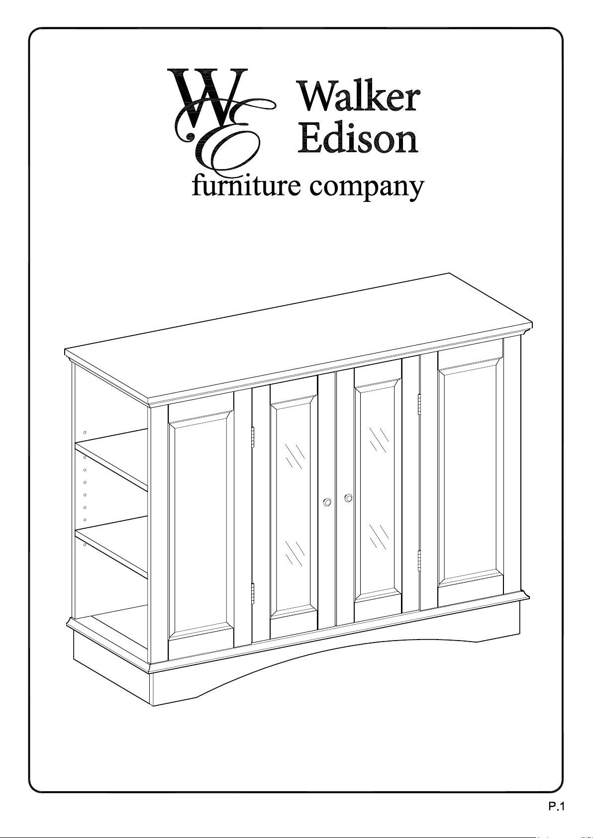
Item #: WQ42BC1
Assembly Instructions
For our most current instructions, to request missing, lost or broken parts, or for any other Customer
Service issues, please visit our website at www.walkeredison.com or call us at 877-207-5906.
Revised 09/2010
Page 2
General Assembly Guidelines
I. Ensure that all parts and hardware are available before beginning assembly.
II. Follow each step carefully to ensure the proper assembly of this product.
III. Two people are recommended for ease in the assembly of this product.
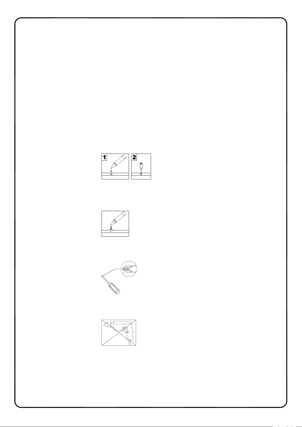
IV. The four main types of hardware used to assemble this product are: wood dowels,
cam bolts and locks, bolts and screws.
V. The provided glue is to secure wood dowels in place. When first inserting dowels,
locate the appropriate hole for the dowel, place a small amount of glue in the hole
and insert the dowel. Wipe away excess glue immediately.
In future assembly steps when dowels are necessary to attach assembly parts
together, place a small amount of glue on the end of the dowel before attaching
parts together. Wipe away excess glue immediately.
VI. A Phillips head screwdriver is required for the assembly of this product.
VII. Power tools should not be used to assemble this product.
P.2
Page 3
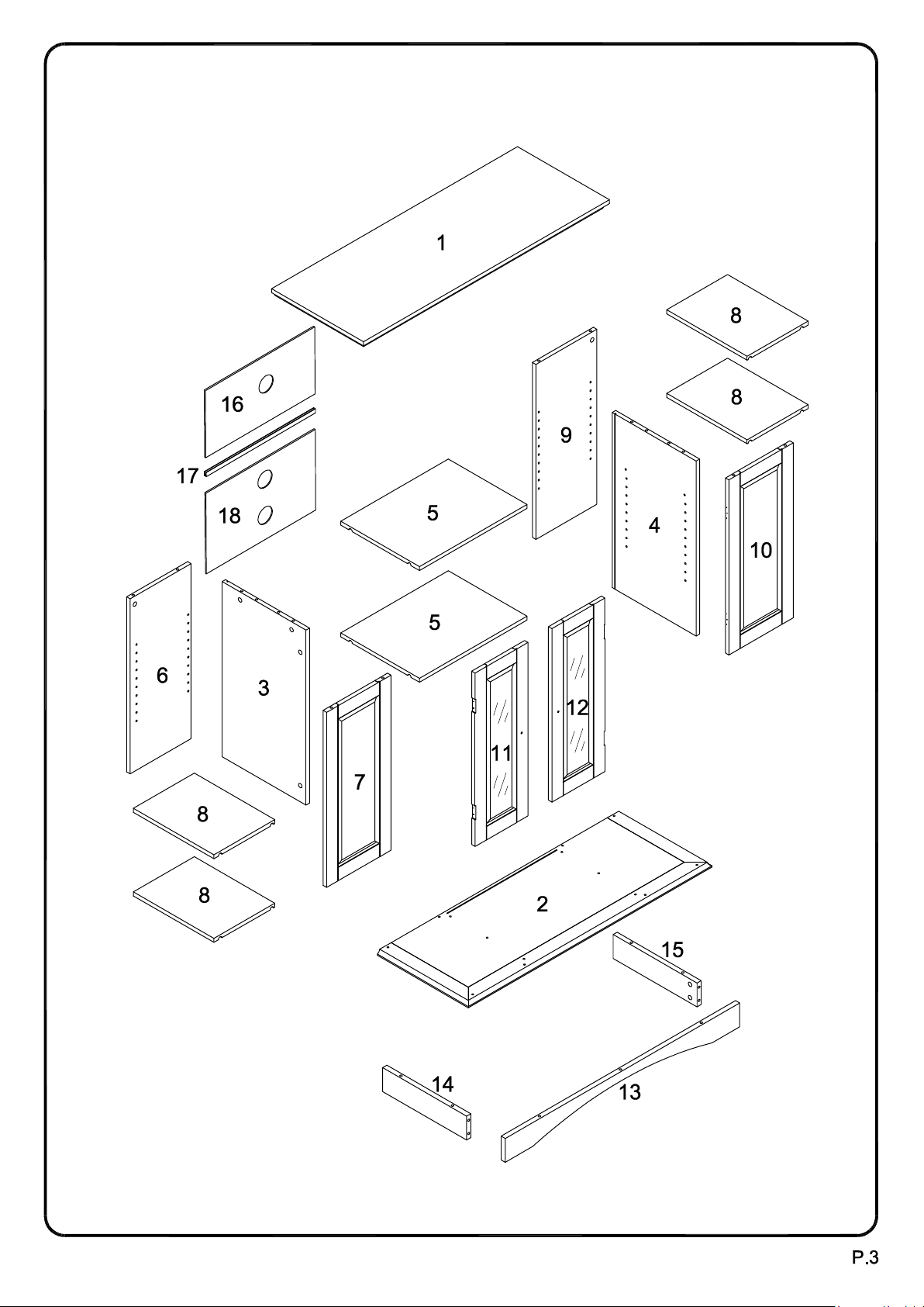
Parts List
Page 4
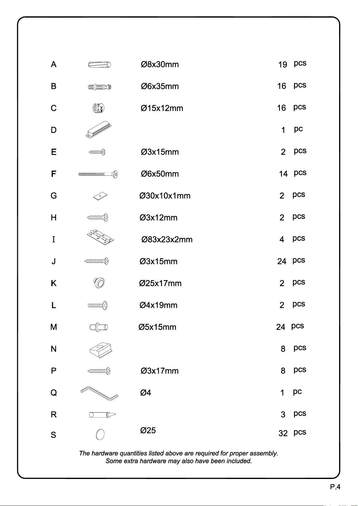
Hardware List
Wood dowel
Cam bolt
Cam lock
Door stopper
Round-headed screw
Large bolt
Door stopper plate
Small screw
Door hinge
Medium screw
Handle
Small bolt
Shelf support pin
Plastic wedge
Large screw
Wrench
Glue tube
Sticker
Page 5
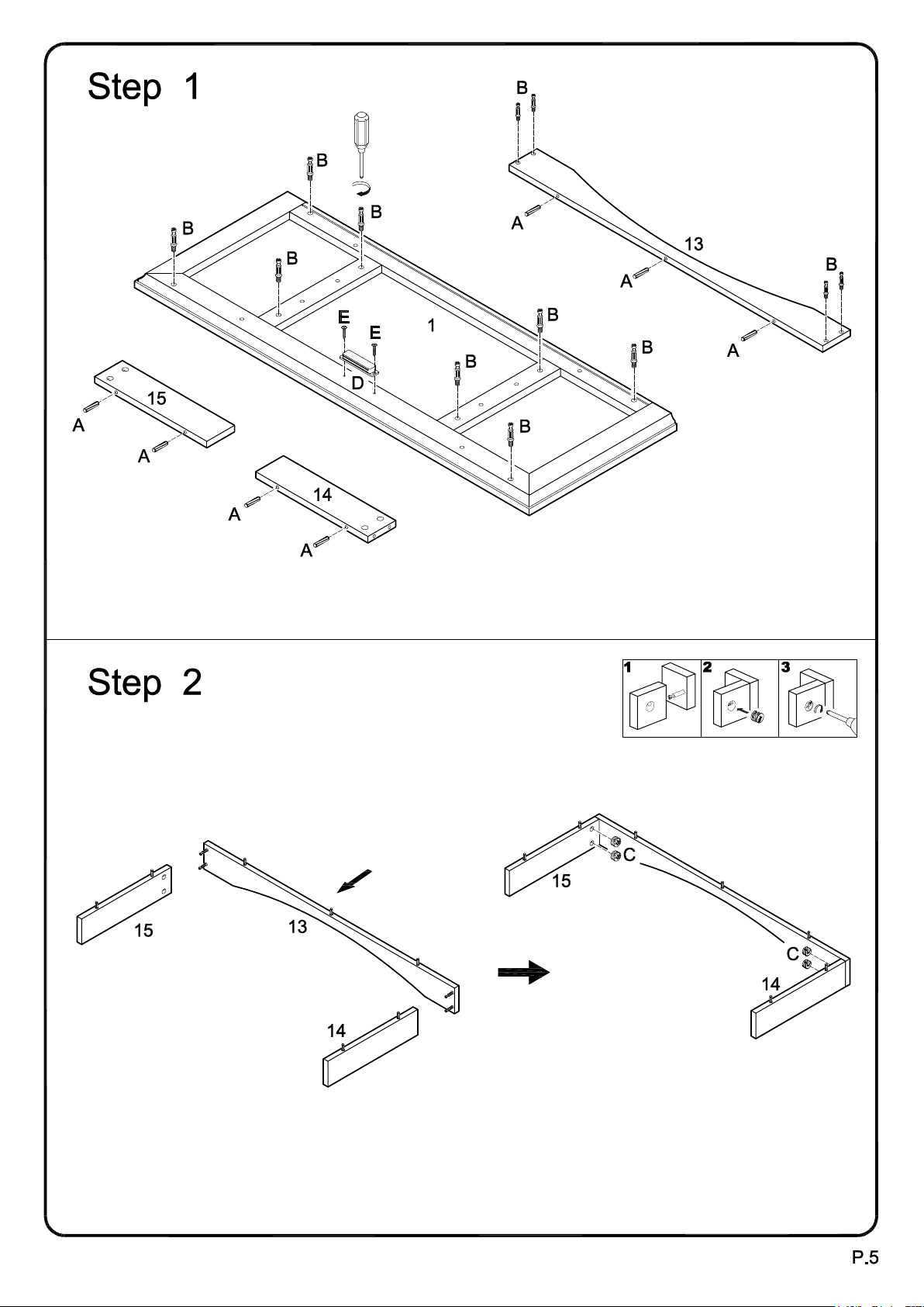
Insert dowels (A) into slats (13,14,15). Screw cam bolts (B) into top panel (1) and slat (13). Attach
door stopper (D) to top panel (1) using round-headed screws (E).
Attach slats (14,15) to slat (13) using cam bolts as guides. Insert cam locks (C) into slats (14,15) and
tighten with a screwdriver.
Page 6
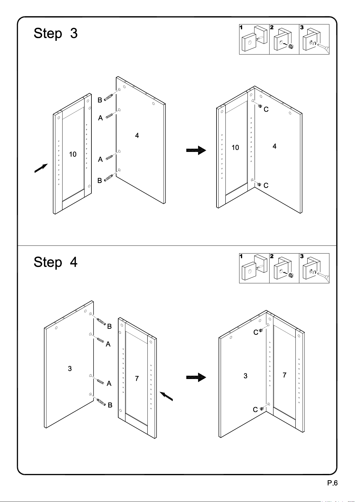
Screw cam bolts (B), and insert dowels (A) into panel (4). Attach panel (10) to panel (4) using cam
bolts and dowels as guides. Insert cam locks (C) into panel (10) and tighten with a screwdriver.
Screw cam bolts (B), and insert dowels (A) into panel (3). Attach panel (7) to panel (3) using cam
bolts and dowels as guides. Insert cam locks (C) into panel (7) and tighten with a screwdriver.
Page 7
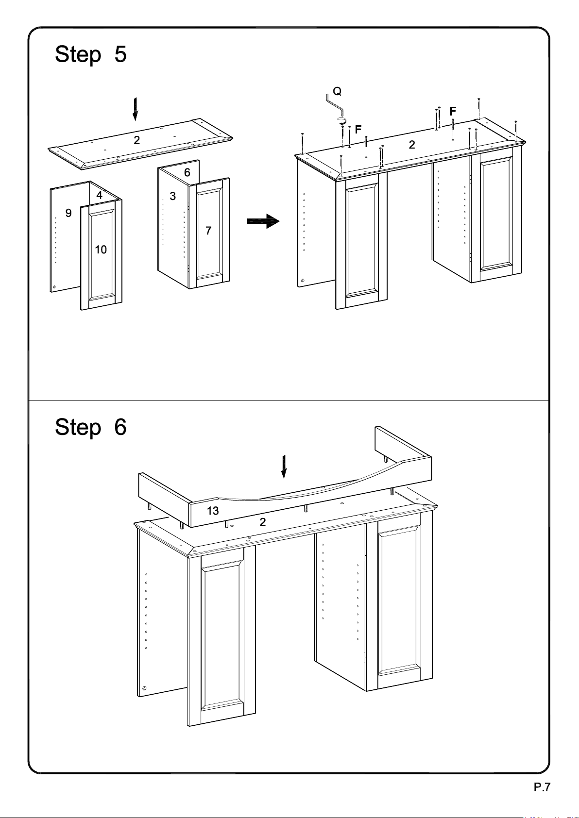
Attach bottom panel (2) to the panel assemblies from Steps 3 and 4, and to panels (6,9) using large
bolts (F) and wrench (Q). Note that panels (6,9) will not be directly attached to the panel assemblies
from Steps 3 and 4.
Attach the base assembly from Step 2 to bottom panel (2) by inserting the dowels of the base assembly
into the pre-drilled holes of bottom panel (2).
Page 8
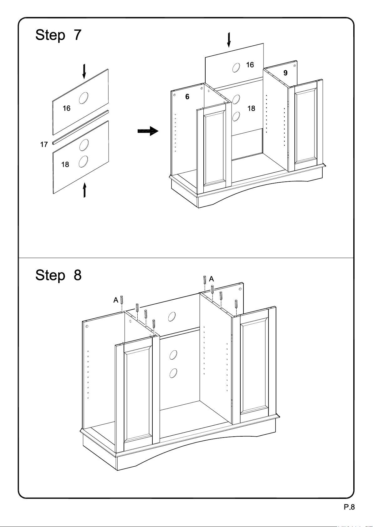
Slide back panel (18), back slat (17) then back panel (16) into the stand assembly.
Insert dowels (A) into the stand assembly.
Page 9
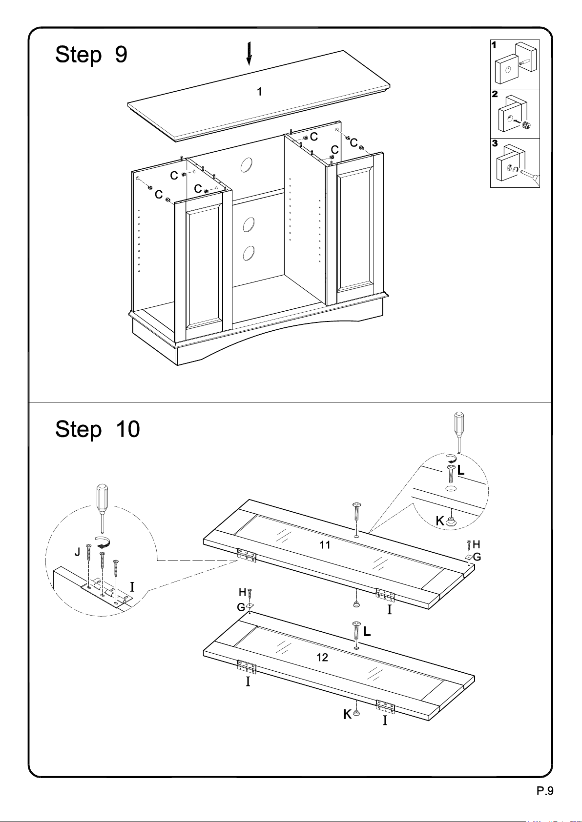
Insert cam locks (C) into the stand assembly. Attach top panel (1) to the stand assembly using cam
bolts and dowels as guides. Tighten cam locks (C) with a screwdriver to secure top panel (1).
Attach door hinges (I) to doors (11,12) using medium screws (J). Attach handles (K) to doors (11,12)
using small bolts (L). Attach door stopper plates (G) to doors (11,12) using small screws (H).
Page 10
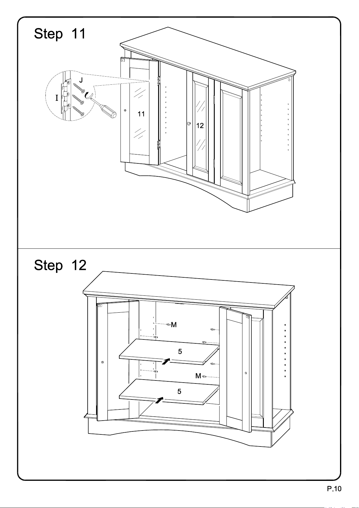
Attach doors (11,12) to the stand assembly at hinges (I) using medium screws (J). For proper
alignment of doors, it may be necessary to loosen small screws (J), adjust the placement of hinges
(I) and re-tighten screws (J).
Insert shelf support pins (M) into the stand at desired shelf heights. Carefully place shelves (5) onto
shelf support pins (M). Note that there will be two shelf support pins (M) on either end of each shelf (5).
Page 11
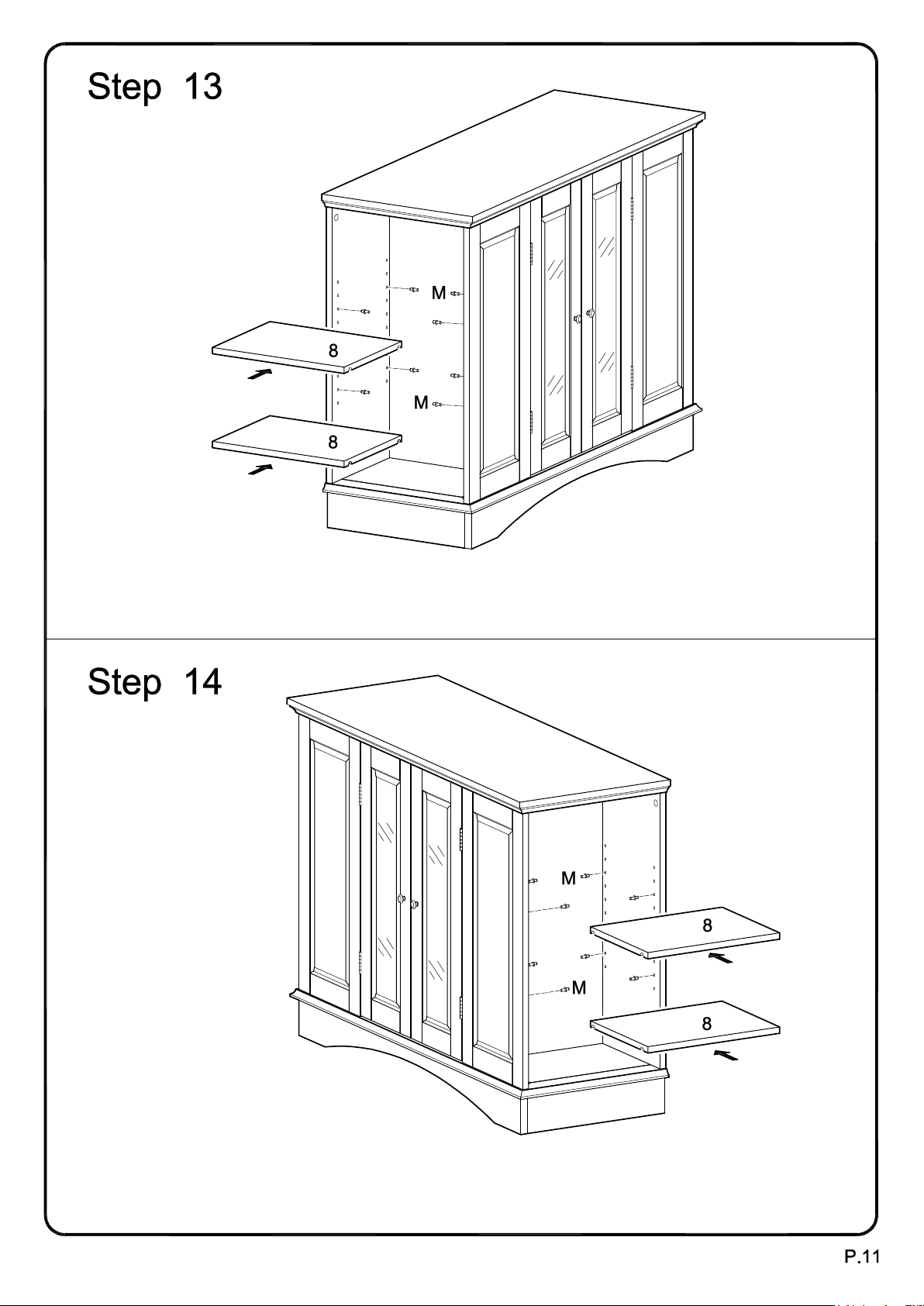
Insert shelf support pins (M) into the stand at desired shelf heights. Carefully place shelves (8) onto
shelf support pins (M). Note that there will be two shelf support pins (M) on either end of each shelf (8).
Insert shelf support pins (M) into the stand at desired shelf heights. Carefully place shelves (8) onto
shelf support pins (M). Note that there will be two shelf support pins (M) on either end of each shelf (8).
Page 12
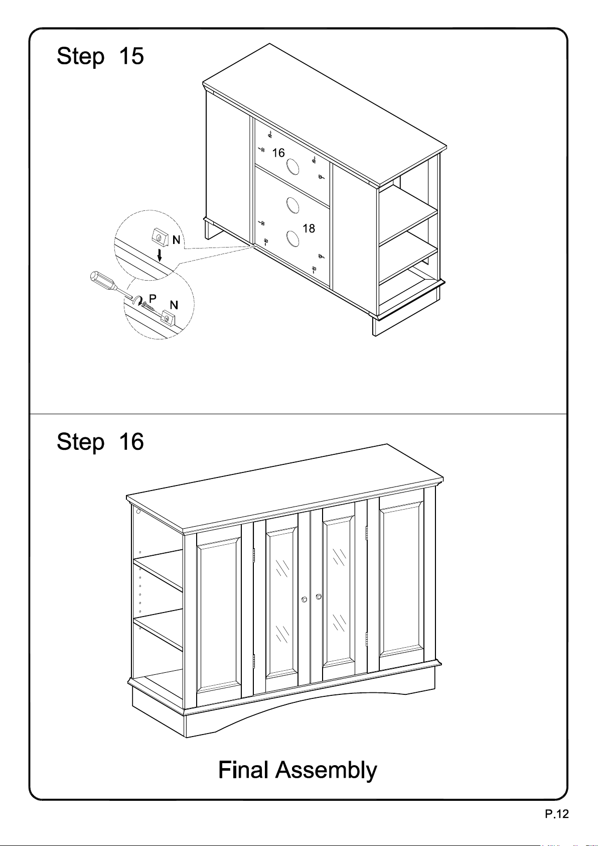
Secure back panels (16,18) using plastic wedges (N) and large screws (P).
 Loading...