

Page 1
OWNER’S MANUAL
Safety, Assembly, Operating, and Maintenance Instructions
and ILLUSTRATED PARTS MANUAL
IH6620 Implement Hitch, RB6650 Rotary Broom, DB6660 Dozer Blade,
SB6670 Two-Stage Snowblower and DB6680 Debris Blower
Please Read and Save These Instructions Effective Date 06-01-01
For Safety, Read All Safety and Operation P/N I375
Instructions Prior to Operating Machine Price $5.00
Page 2

Foreword
Thank you. . .for purchasing a Walker implement. Every effort has been made to provide you with
the most reliable product on the market, and we are sure you will be among our many satisfied customers. If for any rea son thi s produ ct d oes no t per fo rm to y our expectations, please contact u s at
(970) 221-5614. Every customer is important to us. Your satisfaction is our goal.
Please. . .read thi s manual thoroughl y! This manual is to be use d in conjunction with the mo wer
owner’s manual and the engine manufacturer's manual for the specific engine on the mower
model you are using. Before you operate your new impl ement, please read this enti re manual.
Some of the information is crucial for proper operation and maintenance of this product - it will help
protect your investment and ensure that the implement performs to your satisfaction. Some of the
information is important to yo ur safety and must be r ead and understo od to help prev ent possibl e
injury to the operator or others. If anything in this manual is confusing or hard to understand,
please call our service department, at (970) 221-5614, for clarification before operating or servicing this product.
This manual cove rs the Model IH6620 Imple ment Hitch, RB6650 Rotary Broom, DB6660 Dozer
Blade, SB6670 Two-Stage Snowblower, and DB6680 Debris Blower.
All shields and guards must be in place for the proper and saf e operation of these implements. Where they are shown removed in this manu al , it i s for i ll ust ra tio n purpo ses only. Do not
operate this product unless all shields and guards are in place.
Specifications given are based on the latest information available at the time this manual was
produced.
Walker Mfg. Co. is continuall y str iv ing to improve the desi gn and per for ma nc e of its prod uc ts. We
reserve the right t o m ake chan ges i n sp ecifi catio ns and desi gn wi thout th ereby i ncur ring an y obl igation relative to previously manufactured products.
Sincerely,
WALKER MANUFACTURING COMPANY
Bob Walker, President
Page 3

Table of Contents
Owner’s Manual
General Information ________________ 1
HIGHLIGHTED INFORMATION _____________ 1
GLOSSARY ____________________________ 1
IDENTIFYING NUMBER LOCATIONS________ 1
SERVICING OF DRIVETRAIN GEARBOX ____ 3
UNIT DESCRIPTIONS ____________________ 3
Implement Hitch _______________________ 3
Dozer Blade __________________________ 3
Rotary Broom _________________________ 3
Two-Stage Snowblower_________________ 3
Debris Blower_________________________ 3
Specifications _______________________ 4
IMPLEMENT HITCH ______________________ 4
DOZER BLADE__________________________ 4
ROTARY BROOM________________________ 4
TWO-STAGE SNOWBLOWER _____________ 5
DEBRIS BLOW ER _______________________ 6
Component Identification___________ 7
IMPLEMENT HITCH ______________________ 7
DOZER BLADE__________________________ 8
ROT ARY BROOM ________________________ 9
TWO-ST A GE SNOWB LOWER_____________ 10
DEBRIS BLOW ER ______________________ 12
Safety Instructions _________________ 14
BEFORE OPERATING___________________ 14
OPERATING ___________________________ 15
MAINTENANCE ________________________ 16
SAFETY, CONTROL,
AND INSTRUCTION DECALS _____________ 17
Assembly Instructions _____________ 19
SETUP INSTRUCTIONS _________________ 19
IMPLEMENT HITCH_____________________ 19
Implement Hitch Installation ____________ 19
Implement Hitch Wiring________________ 20
DOZER BLADE_________________________ 23
Dozer Blade Assembly ________________ 23
Dozer Blade Installation _______________ 24
ROTARY BROOM_______________________ 24
Rotary Broom Installation______________ 24
Optional Gauge Wheel Installation_______ 26
TWO-STAGE SNOWBLOWER ____________ 27
Snowblower Assembly ________________ 27
Snowblower Installation _______________ 28
DEBRIS BLOWER ______________________ 31
Debris Blower Installation______________ 31
PREOPERATING CHECKLIST ____________ 32
Implement Hitch______________________ 32
Dozer Blade _________________________ 32
Rotary Broom________________________ 32
Two-Stage Snowblower________________ 33
Debris Blower _______________________ 33
Operating Instructions_____________ 34
TRACTOR CONTROLS__________________ 34
STARTING THE MACHINE _______________ 34
IMPLEMENT HITCH CONTROLS __________ 34
Implement Lift Switch _________________ 34
Hitch Locking Lever __________________ 34
DOZER BLADE CONTROLS______________ 35
Angle Adjustment Pin _________________ 35
Trip Spring __________________________ 35
DOZER BLADE OPERATION _____________ 35
Raising and Lowering the Blade ________ 35
Normal Operation ____________________ 35
Rigid Blade Operation_________________ 36
Speed Recommendations______________ 36
ROTARY BROOM CONTROLS____________ 36
Ground Contact Knob_________________ 36
Angle Adjustment Lever _______________ 37
ROTARY BROOM OPERATION ___________ 37
Raising and Lowering the Broom _______ 37
Engaging the Rotary Broom____________ 37
General Sweeping ____________________ 37
Snow Removal_______________________ 38
Lawn Thatching and Leaf Raking _______ 38
TWO-STAGE SNOWBLOWER CONTROLS__ 38
Chute Rotation Handle ________________ 38
Deflector Position Control Knobs _______ 38
TWO-STAGE SNOWBLOWER OPERATION _38
Raising and Lowering the Snowblower___ 38
Engaging the Snowblower _____________ 39
Recommendations For Snowblowing ____ 39
Removing Snow______________________ 40
Clogging Checklist ___________________ 40
DEBRIS BLOWER CONTROLS ___________ 41
Chute Rotation Handle ________________ 41
Deflector Position Control Knob ________ 41
DEBRIS BLOWER OPERATION___________ 41
Raising and Lowering the Debris Blower _41
Engaging the Debris Blower____________ 42
Recommendations for
Operating the Debris Blower ___________ 42
STOPPING THE MACHINE _______________ 42
Page 4

Table of Contents
Maintenance Instructions__________ 43
MAINTENANCE SCHEDULE CHART _______ 43
LUBRICATION _________________________ 44
Rotary Broom Gearbox ________________ 44
Rotary Broom Drive Chain _____________ 44
Two-Stage Snowblower Gearbox ________ 45
Two-Stage Snowblower
Reduction Chain______________________ 45
Grease Fitting and Oil Point Lubrication__ 45
Implement HItch _____________________ 46
Dozer Blade ________________________ 48
Rotary Broom _______________________ 50
T wo-Stage Snowblower _______________ 52
Debris Blower _______________________ 54
REPLACING/REPAIRING ________________ 56
Dozer Blade Cutting Edge______________ 56
Rotary Broom Brush __________________ 56
Rotary Broom Gearbox ________________ 57
Rotary Broom Drive Chain _____________ 57
Rotary Broom Drive Shaft Sprocket______ 58
Two-Stage Snowblower Cutting Edge ____ 59
Two-Stage Snowblower Gearbox ________ 60
Two-Stage Snowblower
Reduction Chain______________________ 60
Two-Stage Snowblower
Reduction Sprocket___________________ 61
Debris Blower Drive Belt _______________ 61
Debris Blower Rotation Pinions _________ 62
ADJUSTMENTS ________________________ 62
Dozer Blade Skid Shoes _______________ 62
Rotary Broom Brush Leveling __________ 63
Rotary Broom Gauge Wheels ___________ 63
Rotary Broom Drive Chain Tension ______ 64
Two-Stage Snowblower Skid Shoes______ 64
Two-Stage Snowblower
Reduction Chain Tension ______________ 64
Debris Blower Front Gauge Wheel_______ 65
Debris Blower Drive Chain Tension ______ 65
Debris Blower Rotation Pinions _________ 66
Debris Blower Rotation Handle _________ 66
TORQUE SPECIFICATIONS ______________ 67
Removal and Storage Instructions _68
REMOVAL ____________________________ 68
Removing Attachments
From Implement Hitch_________________ 68
Dozer Blade ________________________ 68
Rotary Broom _______________________ 68
T wo-Stage Snowblower _______________ 69
Debris Blower_______________________ 69
Removing Implement
Hitch From T ractor ___________________ 70
END OF SEASON STORAGE _____________ 70
Implement Hitch______________________ 70
Dozer Blade _________________________ 70
Rotary Broom________________________ 71
Two-Stage Snowblower________________ 71
Debris Blower _______________________ 71
Illustrated Parts Manual
IMPLEMENT HITCH ASSEMBLY __________ 72
IMPLEMENT HITCH
ELECTRICAL COMPONENTS ____________ 74
DOZER BLADE ASSEMBLY ______________ 76
ROTARY BROOM ASSEMBLY ____________ 78
ROTARY BROOM DRIVE COMPONENTS ___ 80
SNOWBLOWER HOUSING COMPONENTS _82
SNOWBLOWER DRIVE COMPONENTS ____ 84
DEBRIS BLOWER COMPONENTS_________ 86
DEBRIS BLOWER MANUAL
ROTATION COMPONENTS_______________ 88
KEY TO ABBREVIATIONS
USED IN ILLUSTRATED PARTS LIST ______ 90
Warranty___________________________ 91
Page 5

General Information
HIGHLIGHTED INFORMATION
Walker Manufacturing recommends that any service requiring special training or tools be performed
by an authorized Walker Mower Dealer. There are
several general practices to be aware of in the area
of safety. Most accidents associated with the operation or maintenance of a Walker product are
caused by disregardi ng bas ic saf ety pr ecautio ns or
specific warnings. Such accidents, in most cases,
can be prevented by being aware of the dangers
present.
Information of special importance has been highlighted in bold type in this man ual. Refer to Safety
Instructions for the mean ing s of DANGE R, WARNING, CAUTION, IMPORTANT, and NOTE.
GLOSSARY
There are many ter ms th at ar e ei ther uni que to th is
equipment or that ar e used as acronyms. T he following terms and their defin iti ons wil l help whi le using this manual.
• FORW ARD SPEED CONTROL (FSC) controls
the maximum forward speed of the tractor; functioning as a cruise control.
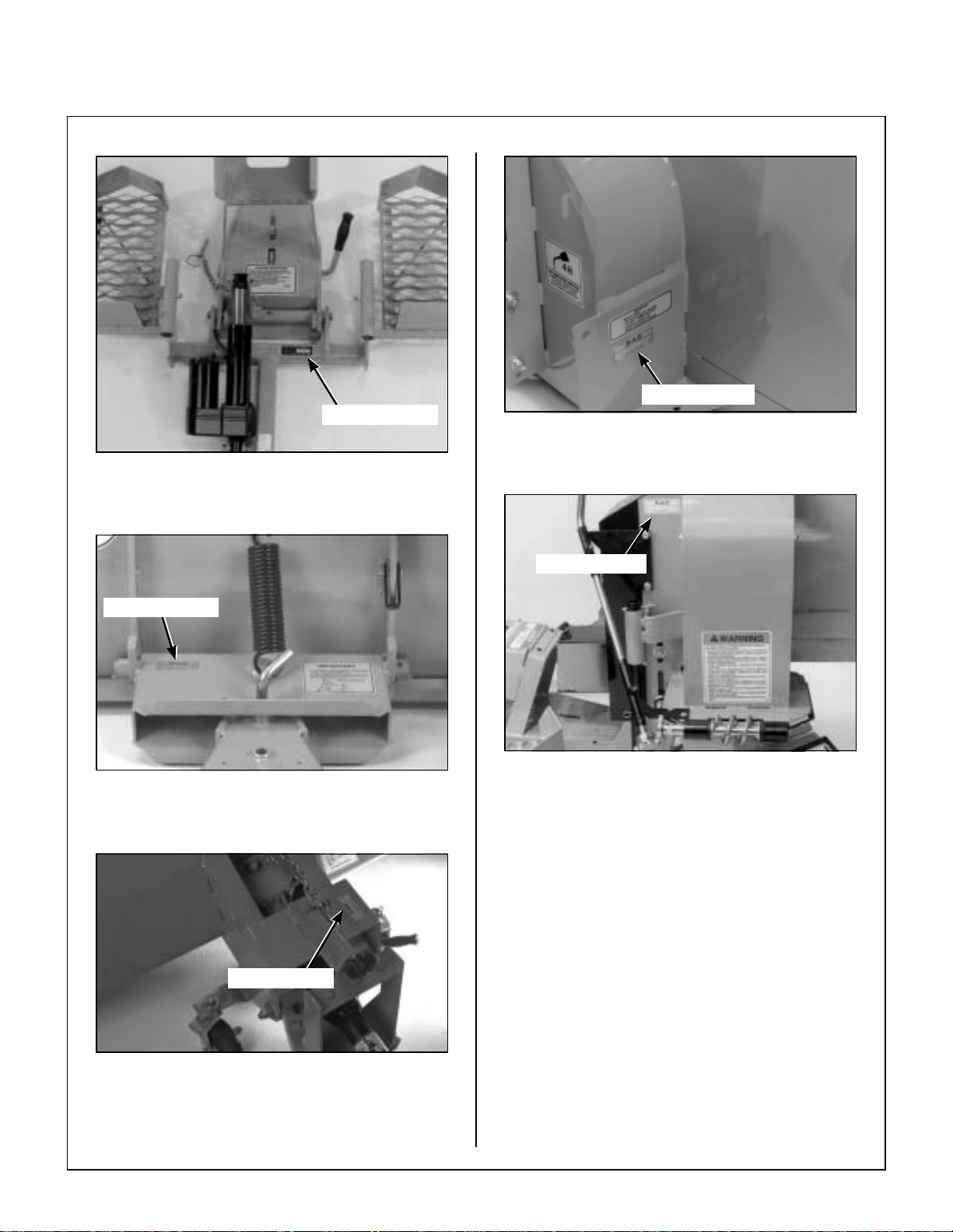
IDENTIFYING NUMBER LOCATIONS
The implement hitch seri al number is affixed to the
top of the male hitch assembly, underneath the
PTO shield. The dozer blade serial num ber is affixed to the LH side of the hitch box on the back
side of the blade. The rotary broom serial number
is affixed on the RH side of the pivot bracket. The
snowblower serial number is affixed on the RH side
of the snowblower head frame. The de bris blower
serial number is a ffixed to th e top RH side of the
hitch. Model and serial numbers are helpful when
obtaining replacement parts and maintenance assistance. For ready refere nce, please record thes e
numbers in the space provided.
Implement Hitch Model No. _______________
Implement Hitch Serial No. _______________
Dozer Blade Model No. __________________
Dozer Blade Serial No. __________________
Rotary Broom Model No. _________________
Rotary Broom Serial No. _________________
IH6620
DB6660
RB6650
• IMPLEMENT r efers to the dozer blade, rotary
broom, two-stage snowblower, or debris blower
used with the tractor with an implement hitch installed.
• LEFT HAND (LH) refers to the left-hand side of
the machine when the operator is seated facing
forward in the tractor seat.
• MACHINE consists of the implemen t installed
on the tractor, functioning as a single unit.
• POWER TAKE-OFF (PTO) transmits engine
power to run the rotary broom, two-stage snowblower, or debris blower.
• RIGHT HAND (RH) refers to the right-hand side
of the machine when the operator is seated facing forward in the tractor seat.
• TRACTOR is the prime mover, including the en-
gine, drivetrain, o perator seat, and contr ols to
operate the implement.
Two-Stage Snowblower Model No. _________
Two-Stage Snowblower Serial No. _________
Debris Blower Model No. _________________
Debris Blower Serial No. _________________
Date of Purchase _______________________
Fill In By Purchaser
SB6670
DB6680
1
Page 6
General Information
Implement Hitch Serial Number Location
(Top View)
Serial Number
Serial Number
Two-Stage Snowblower Serial Number Location
(Rear View and RH View)
Serial Number
Dozer Blade Serial Number Location
(Rear View)
Serial Number
Serial Number
Debris Blower Serial Number Location
(Rear View and RH View)
Rotary Broom Serial Number Location
(Rear View)
2
Page 7

General Information
SERVICING OF DRIVETRAIN GEARBOX
Detailed servicing an d repair of the gearbox used
on the implement attachments is not covered in this
manual. Only routine maintenance and general
service instructions are provided. For the service
of the gearbox during the lim ited warranty period, i t
is important to find a local, authorized servicing
agent of the component manufacturer. Any unau-
thorized work done on these components during
the warranty period may void the warranty. If you
have any difficulty finding an authorized outlet or
obtaining warranty service, please contact our Service Department for assistance:
Walker Manufacturing Company
5925 E. Harmony Road
Fort Collins, CO 80528
1-970-221-5614
A service manual is available for the gearbox from:
Tecumseh Products Co.
900 North Street
Grafton, Wl 53024
Rotary Broom
The rotary broom has a 47- inch (119 cm) sweeping
path and five-position RH/LH ang le head . It is su itable for light snow removal, lawn dethatching/raking and general hard surfa ce sweep ing. It is raised
and lowered automatically with the lift control
switch. The rotary broom is powered by the tractor
PTO through the PTO shaft, gearbox and chain fi nal drive to brush drive shaft. Tire chains and a soft
cab are available as optional equipment.
Two-Stage Snowblower
The 42-inch (107 cm) two-stage snowblower
throws snow up to 40 ft (12 m). It is raised and lowered automatically with the l ift control switch. The
blower spout is controlled with a simple position
control handle. The snowbl ower is pow ered by the
tractor PTO through the PTO shaft, snowblower
drive shaft, and gearbox. Tire chains and a soft
cab are available as optional equipment.
Debris Blower
UNIT DESCRIPTIONS
Implement Hitch
The implement hi tch is required to mount each of
the implements to the tra ctor. It clips on the tractor
in place of the mower dec k in less than a minute.
Each implement slides on the male hitch and easily
locks in place. The mount assembly also includes
operator footrests and an electric power lift. The lift
control switch is mounted on the FSC lever for convenient operator use , and is powered by th e linear
actuator on the implement hitch.
Dozer Blade
The 46-inch (117 cm) dozer blade has a five-position RH/LH angle adjustment. It is used for removal
of snow, loose dirt, and gravel, and is raised and
lowered automatically with the lift control switch.
The dozer blade is d esigned to “trip” forward when
striking a large object, eliminating shock to the tractor and operator. Tire chains and a soft cab are
available as optional equipment.
The debris blower is us ed for parking lot cleaning
and leaf control. It is raise d and lowered autom atically with the lift control switch. The directional
spout adjusts manually. The debris blower is powered by the tractor PTO through the PTO shaft.
Tire chains and a soft cab are availabl e as opt ional
equipment.
IMPORTANT: These imp lements are not intended
for use with Model MS tractors.
3
Page 8

Specifications
MODEL IMPLEMENTS
IMPLEMENT HITCH
Height 10 in. (25 cm)
Width 33-1/2 in. (85 cm)
Length 30 in. (76 cm)
Overall Length Installed on Tractor 69-3/4 in. (177 cm)
Weight 70 lb (32 kg)
Lift 12 Volt DC Electric Ram Linear Actuator, Operated by Toggle Switch
Mounted on FSC Lever
DOZER BLADE
Height 17-1/2 in. (44 cm)
Width 46 in. (117 cm)
Length Standard Hitch: 22-1/2 in. (57 cm)
Long Hitch: 28-1/2 in. (72 cm)
Longest Hitch: 35 in. (89 cm)
Overall Length Installed on Tractor 87 in. (221 cm), Typical
Weight (minimum) 102 lb (46 kg)
Lift 12 Volt DC Electric Ram Linear Actuator, Operated by Toggle Switch
Mounted on FSC Lever
Hitch System Patented Quick Hitch Syste m
Type Blade Multi-Purpose Blade with Reversible and Replaceable Cutting Edge,
Spring Forward Trip Action with Lock Out
Angle Adjustment Five Positions, 0° (Straight Ahead), 15° and 30° LH or RH
Body Construction Blade Thickness: 11 Gauge Steel
Frame Thickness: 3/8 in. (10 mm)
Cutting Edge Thickness: 1/4 in. (6 mm)
Depth Guide Two Adjustable, Replaceable Skid Shoes,
Adjustable from 1/4 to 3/4 in. (6 to 19 mm)
ROTARY BROOM
Height With Broom: 18-3/8 in. (47 cm)
Without Broom: 11-3/8 in. (29 cm)
Overall Width 47-3/8 in. (120 cm)
Sweeping Path Width (Brush Length) 43-1/4 in. (110 cm)
Length (With Female Hitch) Approx. 45 in. (114 cm)
Overall Length Installed on Tractor 105-1/2 in. (268 cm)
Weight (With Female Hitch) 205 lb (93 kg)
Lift 12 Volt DC Electric Ram Linear Actuator, Operated by Toggle Switch
Mounted on FSC Lever
4
Page 9

Specifications
MODEL IMPLEMENTS
ROTARY BROOM (continued)
Hitch System Patented Quick Hitch Syste m
Type Brush 18 in. (46 cm) Diameter Polypropylene or Steel, Clockwise Rotation
Brush Drive PTO Shaft Driving Center Mounted Gearbox
Primary Reduction Gearbox, 2.78:1 Ratio
Secondary Reduction #40 Chain and Sprockets, 3.27:1 Ratio
Maximum Brush Speed 260 RPM
Broom Angle Adjustment Five Positions, 0° (Straight Ahead), 12.5° and 25° LH or RH
Working Width At Maximum Angle (25°) 39-3/16 in. (100 cm)
Ground Contact Pressure Screw Adjustment with Viscous Damper
Body Construction 14 Gauge Steel
Capacity Clears up to 4 in. (10 cm) snow
TWO-STAGE SNOWBLOWER
Height (Without Chute) 20-3/4 in. (53 cm)
Width 42 in. (107 cm)
Clearing Width 42 in. (107 cm)
Length (With Female Hitch) 22-1/2 in. (57 cm)
Overall Length Installed on Tractor 95 in. (241 cm)
Weight (With Female Hitch) 210 lb (95 kg)
Lift 12 Volt DC Electric Ram Linear Actuator, Operated by Toggle
Switch Mounted on FSC Lever
Hitch System Patented Quick Hitch Syste m
Type Blower Two-Stage with 12-7/8 in. (33 cm) Diameter Auger and
15-3/4 in. (40 cm) Diameter, 3-Blade Impeller, Clockwise Rotation
Snowblower Drive PTO Shaft Driving Blower Wheel
Impeller Drive Chain, #40
Driving Sprocket: H40C11
Driven Sprocket: H40B32
Auger Drive Worm Gearbox, 5:1 Ratio
Discharge Angle Adjustment Chute Direction Rotation 228° by Crank, Adjustable Spout
Deflector, Adjustable from Operator Seat, Up to 40 ft (12 m)
Discharge Distance
Body Construction Frame Thickness: 14 Gauge Steel
Side Thickness: 11 Gauge Steel
Impeller Housing Thickness: 14 Gauge Steel
Cutting Height 19 in. (48 cm)
Depth Guide Two Adjustable, Replaceable Skid Shoes,
Adjustable from 1/4 to 3/4 in. (6 to 19 mm)
5
Page 10

Specifications
MODEL IMPLEMENTS
DEBRIS BLOWER
Height 28-1/2 in. (72 cm)
Width 26 in. (66 cm)
Length 34-3/4 in. (88 cm)
Overall Length Installed on Tractor 102-1/2 in. (260 cm)
Weight (With Female Hitch) 130 lb (59 kg)
Lift 12 Volt DC Electric Ram Linear Actuator, Operated by Toggle
Switch Mounted on FSC Lever
Hitch System Patented Quick Hitch Syste m
Type Blower 13-1/2 in. (34 cm) Diameter, 8-blade Aluminum Impeller,
Counterclockwise Rotation
Blower Drive PTO Shaft Driving Blower Wheel
Recommended RPM 3600 RPM (4000 RPM Maximum)
Airflow at 4000 RPM 2000 cfm
Noise Level at 4000 RPM Approx. 90 Dba
Approximate Required Horsepower 14 HP (10.4 kw)
Air Velocity Mean: 125 mph (201 km/h)
Maximum: 160 mph (257 km/h)
Discharge Angle Adjustment Chute Direction Rotation 230° by Crank,
Adjustable from Operator Seat
Outlet Area 25 in.² (161 cm²)
NOTE: The manufacturer reserves the right to make changes in specifications shown herein at any time
without notice or obligation.
6
Page 11
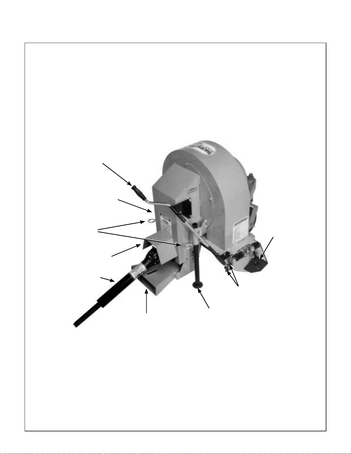
Component Identification
IMPLEMENT HITCH
Footrest
Male Hitch
Assembly
Safety Chain
Assembly
PTO Shie ld
NOTE:Control Identification shown in
Operating Instructions section
and in
Illustrated Parts Manual.
Male Quick
Hitch Latch
Footrest
Linchpin
Mounting
Tube
Linear Actuator
Linear Actuator
Electrical Connector
Mounting
Tube
Hitch Locking
Lever
Jam Nut
Implement Hitch Top View (Not Installed)
7
Page 12
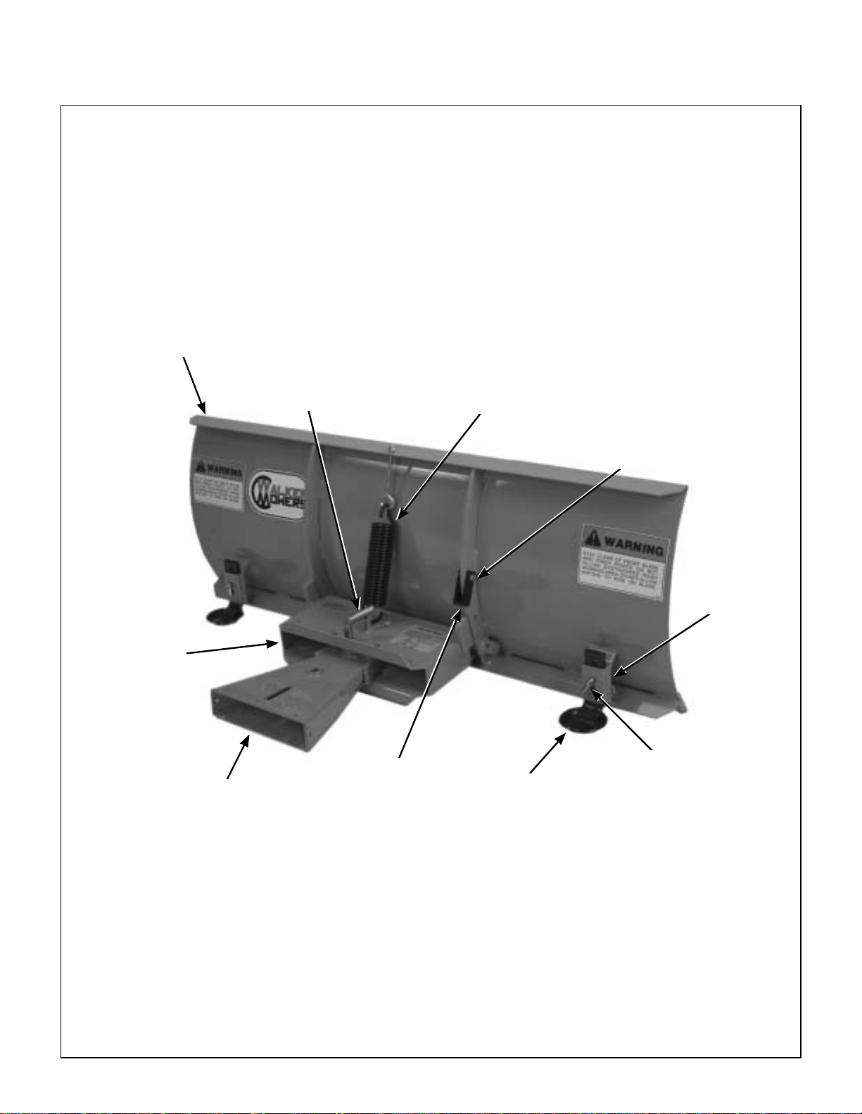
Component Identification
DOZER BLADE
Welded Blade
Angle
Adjustment Pin
Trip Spring
Trip Spring
Lockout Pin
Hitch
Box
Female
Quick Hitch
Trip Spring
Lockout Bracket
Skid Shoe
Skid Shoe
Bracket
Skid Shoe
Pin
Dozer Blade Rear View and Right Side View (Not Installed)
8
Page 13
Component Identification
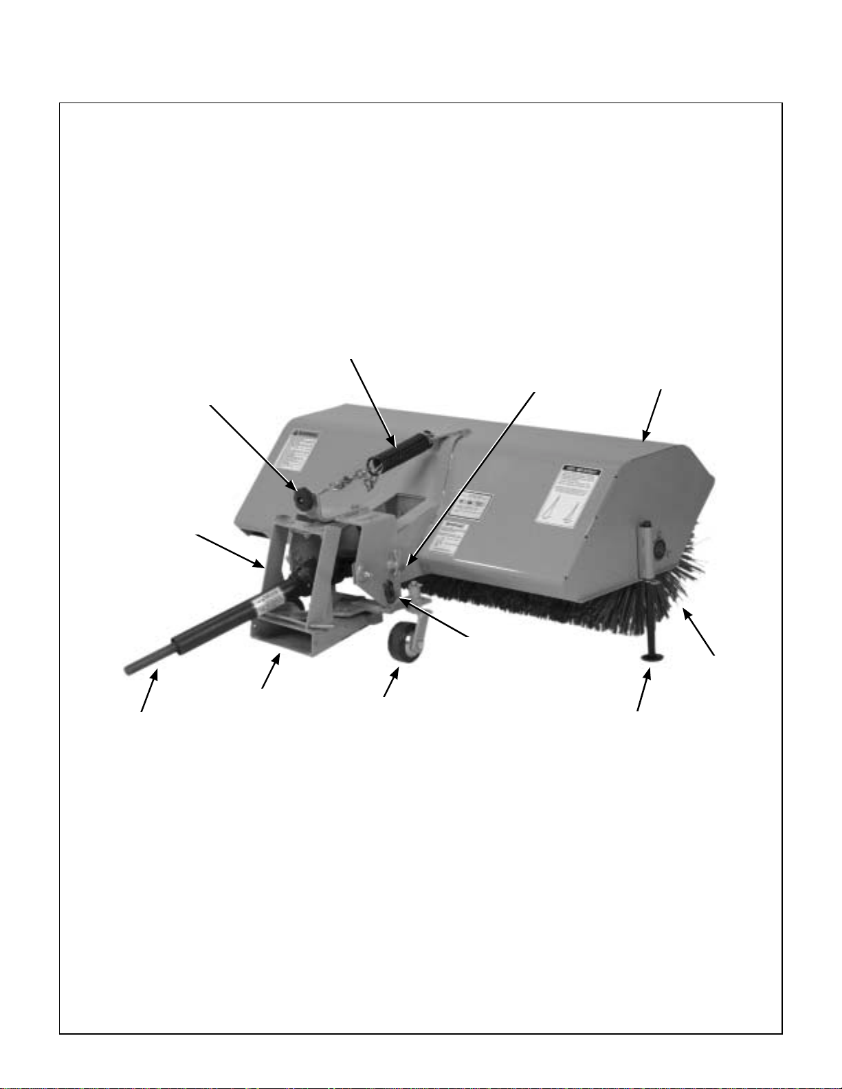
ROTARY BROOM
Tension Spring
Ground Contact
Knob
Stopper
Pin
Rotary Broom
Housing
Pivot Bracket
PTO Shaft
Female Hitch
Plastic
Wheel
Broom Angle
Adjustment Lever
Brush
Parking
Stand
Rotary Broom Rear View and Right Side View (Not Installed)
9
Page 14
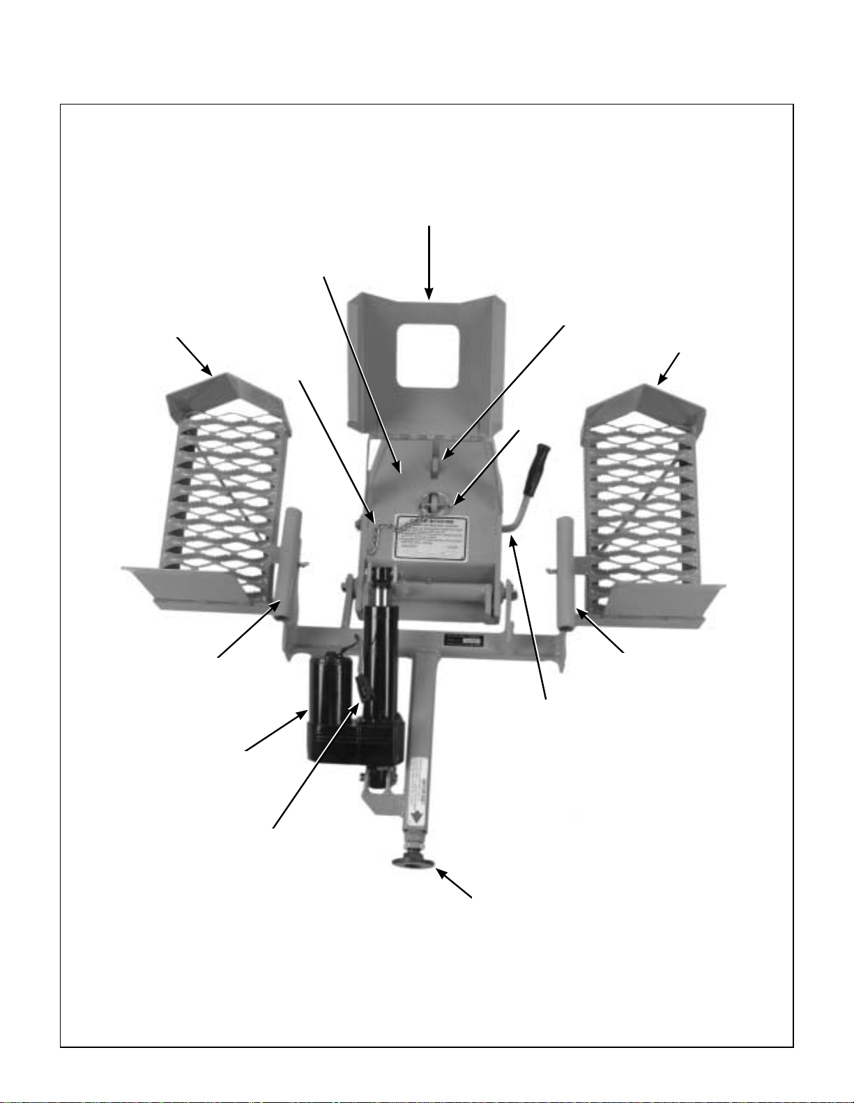
Component Identification
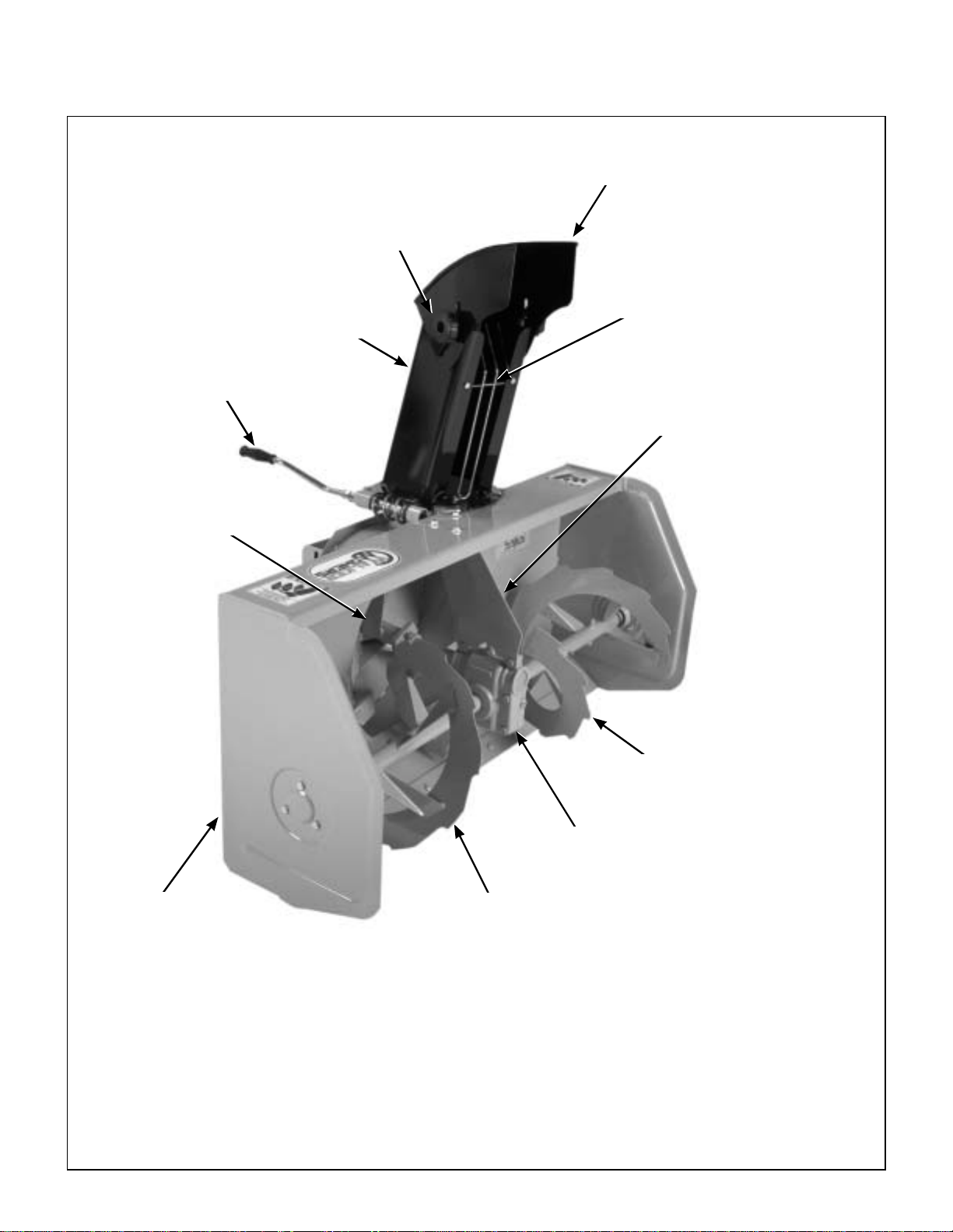
TWO-STAGE SNOWBLOWER
Deflector Position
Chute Rotation
Handle
Fan
Deflector
Control Knob
Hand Guard
Chute
Gearbox Support
Bracket
10
Frame
Auger
Gearbox
Auger
Two-Stage Snowblower Front View and Right Side View (Not Installed)
Page 15
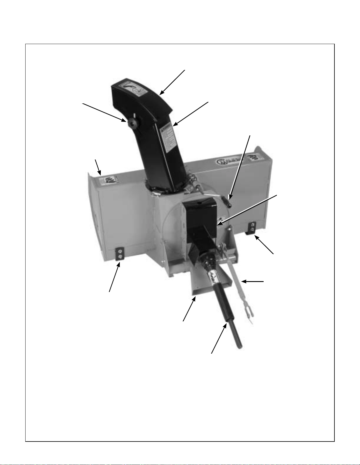
Component Identification
Deflector
Deflector Position
Control Knob
Snowblower
Housing
Chute
Chute
Rotation Handle
Reduction
Box Cover
Skid Shoe
Skid Shoe
Two-Stage Snowblower Rear View (Not Inst alled)
Parallel Bar
Female Quick Hitch
PTO Drive Shaft
11
Page 16
Component Identification
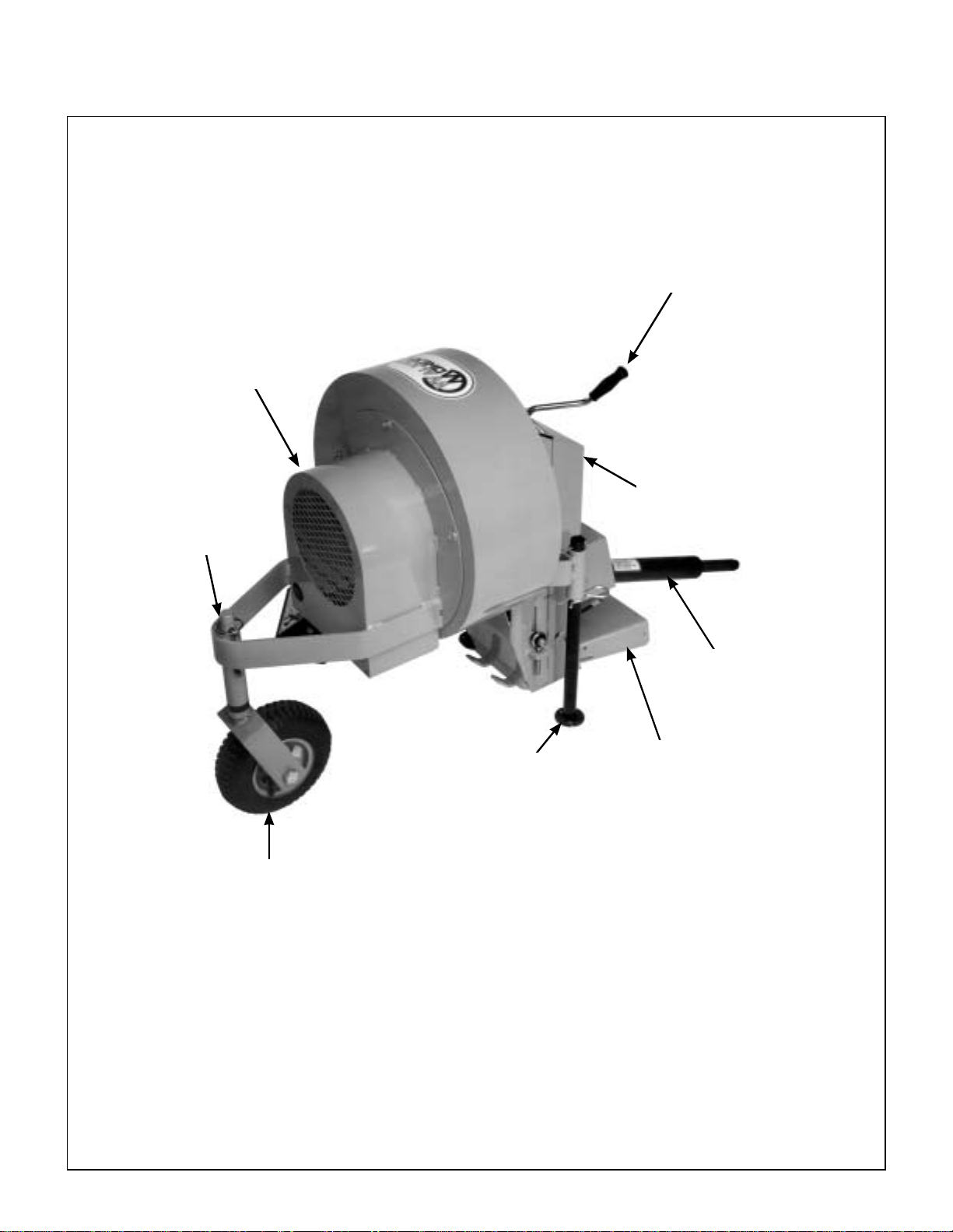
DEBRIS BLOWER
Blower Motor
Housing
Chute Rotation Handle
Belt Guard
Linchpin
Pivot Wheel
Parking Stand
PTO Drive Shaft
Female Quick
Hitch
12
Debris Blower Front View and Left Side View (Not Installed)
Page 17
Component Identification
Chute Rotation Handle
Belt Guard
Parking Stand
Pins
Driveline Guard
PTO Drive Shaft
Deflector Position
Control Knob
Rotation Pinions
Parking Stand
Female Quick
Hitch
Debris Blower Rear View and Right Side View (Not Installed)
13
Page 18
Safety Instructions
Pay particular attentio n to any information labeled
DANGER, WARNING, CAUTION, IMPORTANT,
and NOTE in this manual.
When you see the Safety Alert Symbol ( ),
read, understand, and follow the instr uctions. Failure to comply with safety instructions may result in
personal injury.
The seriousness or degree of imp ortance of each
type of information is defined as follows:
DANGER
An IMMEDIATE hazard that WILL result in
severe personal injury or DEATH, if warning is ignored and proper safety precautions are not taken.
WARNING
A POTENTIAL hazard that COULD result in
severe personal injury or DEATH, if warning is ignored and proper safety precautions are not taken.
Walker Manufacturing cannot pred ict every potentially dangerous situat ion . The re fore, i tem s la bel ed
as such in th is m anu al do n ot cover all conc eiv ab le
situations. Any pe rson using procedure s, tools, or
control techniques not recommended by Walker
Manufacturing must take full responsibility for safety.
The Walker Tractor and Implement attachments
have been designed wi th many safety features to
protect the operator from personal harm or injury.
However, it is necessary for the operator to use safe
operating procedures at all times. Failure to follow
safety instructions contained in this manual
may result in personal injury or damage to
equipment or property.
If you have any questions concerning setup, operation, maintenance, or safety, please contact your
authorized Walker Mower Dealer or call Walker
Manufacturing Company at (970) 221-5614.
BEFORE OPERATING
1. Read and understand the contents of this
OWNER'S MANUAL before operating the
machine. Become thoro ughly familiar with all
controls and how to stop the machine and disengage the controls quickly. Replacement Owner's
Manuals are available by sending the Model and
Serial Number to:
Possible hazards or unsafe practices that
MAY result in MODERATE personal injury
or property damage, or machine damage, if
warning is ignored and proper safet y precautions are not taken.
IMPORTANT: Identifies mechanical information de-
manding special attention, since it deals with the possibility of damaging a part or parts of the machine.
NOTE: Identifies information worthy of s pecial attention.
CAUTION
Walker Manufacturing Company
5925 E. Harmony Road
Fort Collins, CO 80528
2. Never allow children to operate or give rides
on the machine. Do not allow adults to operate
without proper instruction.
3. Do not allow anyone other than the operator on
the machine.
4. Keep everyone, especially children and pets, a
safe distance away from the area being cleaned.
Do not operate with bystanders in the area.
5. Do not ope rate the mac hine wearing sneakers,
tennis shoes, or similar lightweight footwear.
Wear substantial protective footwear that will
improve footing on slippery surfaces.
6. The snow or leaves can sometimes hide objects
that might clog the snowblower or debris blower
chute, or other wise cause damage . Clear the area of doormats, sle ds, boards, wires an d other
debris.
14
Page 19

Safety Instructions
7. Do not wear loose fitting clothing that could
get caught in moving par ts. Always wear ade-
quate protective clothing including long pants.
Wearing safety glasses, safety shoes, and a
helmet is advisable and required by some local
ordinances and insurance regulations.
8. Prolonged exposure to loud noise can cause
impairment or loss of he aring. Oper ator hear-
ing protection is recommended. Wear a suitable hearing pro tective devi ce, such as e armuffs
or earplugs.
9. K eep all prote cti ve shiel ds and safety devic -
es in place. If a protective shield, safety device,
or decal is da maged, unusabl e, or missing, re pair or replace it before operating the machine.
10. Be sure any interlock switches are function-
ing correctly so th e engine canno t be started
unless the Forward Speed Control lever is in
the NEUTRAL position and the PTO clutch is in
the DISENGAGED position. Also, the engin e
should stop if the operator lifts off the seat wit h
the PTO clutch in the ENGAGED position.
OPERATING
NOTE: Refer to the Walker Rider Lawnmowers
OWNER’S MANUAL for safety instructions for
operating the tractor.
1. O per ate th e machi ne onl y in dayl ight or in goo d
artificial light with good visibility of areas being
cleaned.
2. Sit on the seat when starting the engine and operating the ma chine. Keep feet on footrests at all
times when the tracto r is moving and/ or the implement is operating.
3. An inexpe rienced opera tor should learn to steer
(maneuver) the tractor with a slow engine
speed before attempting any operating. Be
aware that, with the front mounted implement
configuration, the back of t he ma chine s wing s to
the outside during turns.
4. Re memb er, for an emerg enc y st op, th e for ward
motion of the tractor can always be stopped by
pulling the Forward Speed Control (FSC) into
the NEUTRAL-PARK position.
11. Never attempt to make any adjustments
while the engine is running, except where specifically instructed to do so.
12. Handle gasoline or diesel fuel with care.
Gasoline is highly flammable and its vapors are
explosive:
a. Use an approved fuel container.
b. Never add fuel to a run ning engine or ho t
engine (allow hot engine to cool several
minutes).
c. Keep matches, cigarettes, cigars, pipes,
open flames, or sparks away from the fuel
tank and fuel container.
d. Always fill the fuel tank outdoors using
care. Fill to about one inch from the top of
the tank. Use a funnel or spout to preven t
spilling.
e. Replace the machine fuel cap and contain-
er cap securely and clean up any spilled
fuel before starting the engine.
5. Di sengage the PTO clutch and put the FSC in
the NEUTRAL-PARK position before starting
the engine (an ig nition inter lock swi tch norm ally
prevents starting of the tr actor if these controls
are in the OPERATING position).
6. Do not run the engine in a confined area with-
out adequate ventilation. Exhaust fumes are
hazardous and can be deadly.
7. Do not carry passengers - maximum seating
capacity is one (1) person.
8. Make sure the au ger, brush, or debris blower is
clear of snow, ice, or debris before engaging the
PTO clutch .
9. Be careful never to throw snow or blow debris towards people or cars, and never allow anyone in
front of the implement.
10. Watch out for hazards hidden under snow or
leaves that coul d enter t he chute or blower w hile
operating.
11. Avoid sudden start s or stops. Before backing
the machine up, look to the rear to be sure no
one is behind the machine . Watch carefully for
traffic wh en cr oss ing or w ork i ng ne ar ro ad wa ys.
15
Page 20

Safety Instructions
12. Disengage the PTO clutch when transporting the
machine.
13. Do not operate across the face of slopes. Use
extreme caution when changing direction on
slopes. Do not attempt to clear steep slopes.
14. Never adjust gauge wheels or skid shoes
with the engine running. Before adjusting
height or se rvicing, disengage the PTO clu tch,
stop the engine, and remove the ignition key.
Wait for all movement to stop before getting off
the seat.
NOTE: The PTO brake should normally stop
drive line rotation within 5 seconds of disengaging the PTO clutch.
15. D o not operate the snow blower with the blower
spout assembly rem oved.
16. If snowblower clogs:
a. Disengage the PTO clutch, stop the en-
gine, and remove the ignition key before
leaving the seat.
b. LOOK to make sure PTO shaft and auger
movement has stopped before trying to unclog the snowblower.
c. Disconnect the fuel solenoid wire [diesel
engines] or spark plug wire(s) [gasoline
engines].
d. Do not use hands or feet to unclog the
snowblower - use a stick or similar tool.
17. If the implement strikes a solid object or the machine begins to vi brate abnorma lly , immediately
disengage the PTO clutch, stop the engine,
and wait for all moving parts to stop. Dis-
connect the fuel so lenoid wire [die sel engines] or
the spark plug wire(s) [gasoline engines] to prevent accidental starting. Thoroughly inspect the
implement and repair any damage before restarting the engine and operating the machine.
Make sure imp lement compon ents are in good
condition and al l bo lts are tight.
18. D o not touch the engine or muffler while the
engine is running or immediately after stopping
the engine. These areas may be hot enough to
cause serious burns.
19. When leaving the machine unattended, disengage the PTO clutch , stop the engine, and remove the ignition key.
MAINTENANCE
NOTE: Refer to the Walker Rider Lawnmowers
OWNER’S MANUAL for proper tractor maintenance procedures.
1. To prevent accidental starting of the engine
when servicing or adjusting the machine, remove the key from the ignition switch and disconnect the fuel solenoid wire [diesel engines] or
the spark plug wire(s) [gasoline engines].
2. To re duce fire hazards, keep the engine free of
grass, leaves, exc essi ve g rea se , an d di rt .
3. K eep al l nuts, bo lts, an d scr ews ti ght to ensure
the machine is in a safe, working condition.
4. Perform only maintenance instructions described in this manual. Unauthorized mainte-
nance operations or machine modifications may
result in unsafe operating conditions.
5. If the engine must be running to perform a maintenance adjustment, keep hands, feet, and
clothing away from moving parts. Do not
wear jewelry or loose clothing.
6. Always use proper engine service manuals
when working on the engine. Unauthorized
maintenance operations or modifications to the
engine may result in unsafe operating conditions.
7. Alt ering the machine in any m anner which adversely affects its operation, performance, durability, or use will VOID the wa rranty and may
cause hazardous cond it ions.
8. Never attempt to disconnect any safety devices
or defeat the pur p ose of th ese safet y d evi ces.
9. Do not chan ge the eng ine gov ernor set ting s or
overspeed the engine. The governor has been
factory-set for ma ximum-safe engine operating
speed.
10. Use genuine factory replacement parts. Substitute parts may result in product malfunction
and possible in jury to the o perator and/or othe rs.
IMPORTANT: Keep all applicable manuals
immediately accessible to anyone who may
operate or service this machine.
16
Page 21
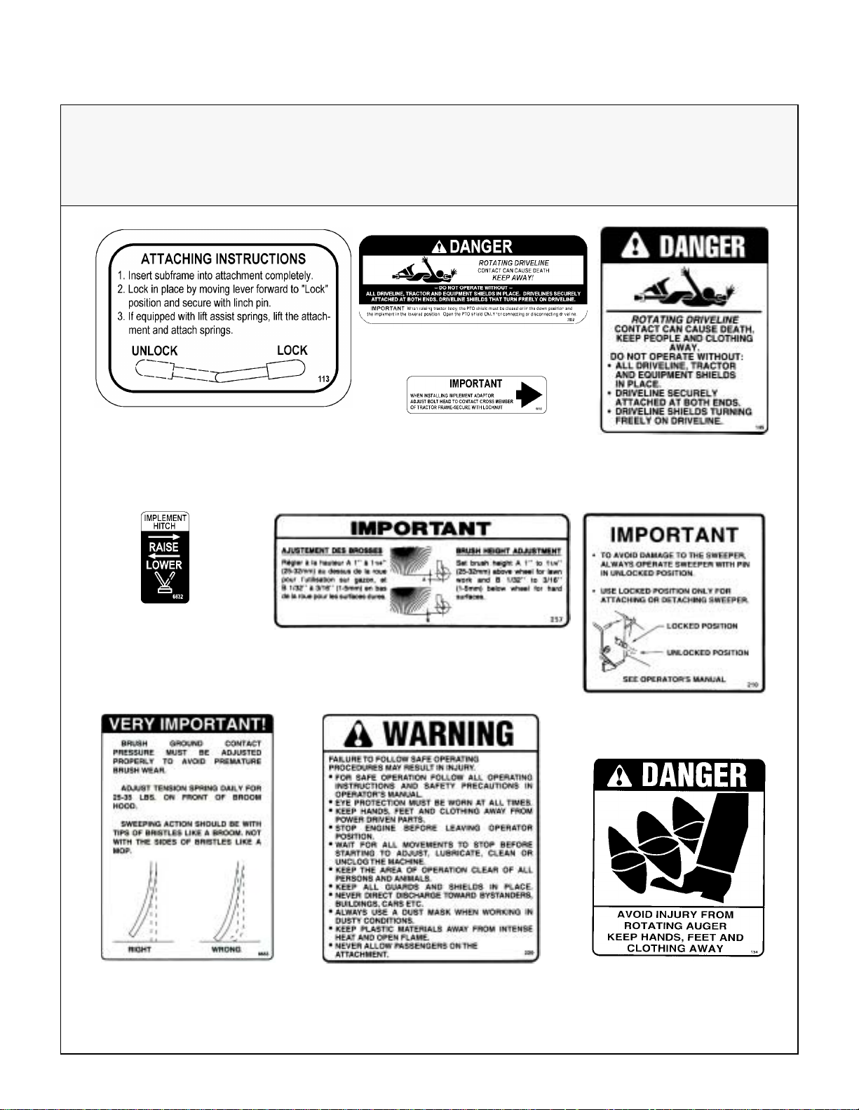
Safety Instructions
Implement Hitch
(Walker P/N 6632)
SAFETY, CONTROL, AND INSTRUCTION DECALS
Safety, Control, and Instruction Decals are installed on the machine. If any are missing, illegible, or
damaged, a replacement should be ordered and installed before putting the machine into operation. The
Decal Part Number i s listed below and in the Parts Manual; the Decal Location is shown in the Parts Manual.
PTO Shield (Walker P/N 7822)
Attaching Hitch
(Walker P/N I393)
(RAD P/N 657364)
Hitch Mount Adjust
(Walker P/N 6618)
Brush Height (RAD P/N 661521)
Rotating Driveline
(Walker P/N I395)
(RAD P/N 657763)
Important - A void Damage
(RAD P/N 660328)
Brush Ground Contact
(RAD P/N 661052)
Safety Procedures
(RAD P/N 660988)
Rotating Auger
(Walker P/N I394)
(RAD P/N 657762)
17
Page 22
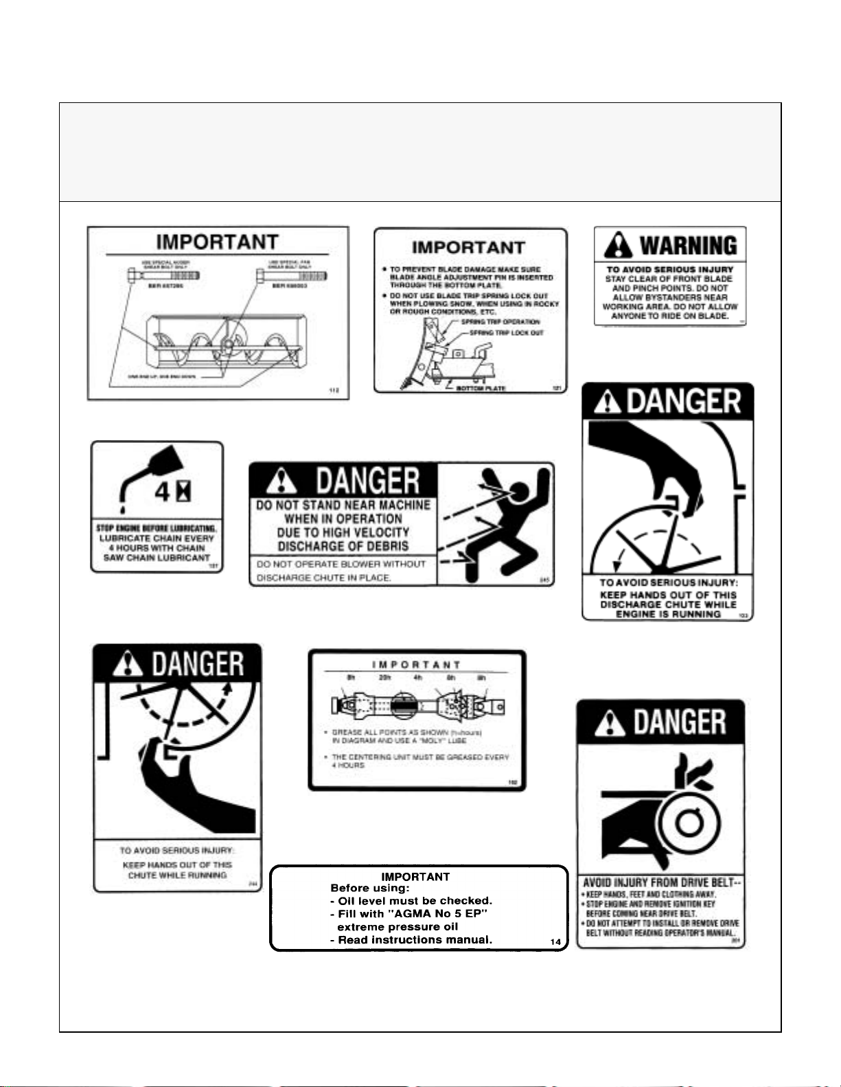
Safety Instructions
Lubricate Chain
(RAD P/N 657804)
SAFETY, CONTROL, AND INSTRUCTION DECALS
Safety, Control, and Instruction Decals are installed on the machine. If any are missing, illegible, or
damaged, a replacement should be ordered and installed before putting the machine into operation. The
Decal Part Number is listed below and in the Parts Manual; the Decal Location is shown in the Parts Manual.
Stay Clear Blade
(RAD P/N 657524)
Use Shear Bolts (RAD P/N 657346)
Danger, High Velocity (RAD P/N 661248)
Trip Spring Lockout
(RAD P/N 657503)
Keep Hands Out
(Walker P/N I396)
(RAD P/N 657761)
Avoid Serious Injury
18
(RAD P/N 661247)
Grease All Points (RAD P/N 6586708)
Check Oil Level (RAD P/N 655683)
Drive Belt Injury
(RAD P/N 660265)
Page 23
Assembly Instructions
SETUP INSTRUCTIONS
Walker Implements are shipped partially assembled. After uncrati ng t he imp le men t ad apto r and /or
implement(s), initial setup is required.
NOTE: During the process of unpacking, any damaged or missing parts should be noted and reported
to the delivering ca rrier immediately (put in wri ting
within 15 days). The carrier will provide directions
for proceeding with a claim to receive compensation
for damage.
IMPLEMENT HITCH
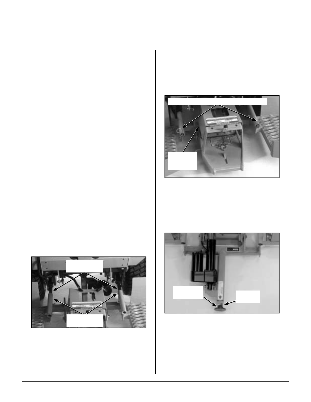
Implement Hitch Installation
1. Remove the mower deck from the tractor if necessary. Refer to the appropriate Tractor Owner’s Manual.
2. Lightly grease each tractor support arm (2) on
the tractor. Refer to Implement Hitch Installa-
tion photo for location of tractor support arms.
IMPORTANT: If the tractor body needs to be raised,
the PTO shield must be in the closed or down position and the implement must be in the lowered
position. The only time the PTO shield needs to be
open or raised is when connecting or disconnecting
the driveline for the rotary broom, snowblower, or
debris blower.
Hitch Pins Lock Hitch on Support Arms
PTO Shield
in CLOSED
Position
PTO Shield in CLOSED Position
3. Engage the hitch frame tube sockets on the
tractor support arms. Slide the implement hitch
onto the support arms approxim ately 3 in. (76
mm).
4. Install the hitch pin through the hole on the end
of each support arm to loc k the hitch in place.
Two (2) hitch pins are included i n the owner’s
packet of materials.
Grease Tractor
Support Arms
Hitch Frame
Tube Sockets
Implement Hitch Installation
5. Loosen the 3/4-10 jam nut on the end of the implement Hitch. Adjust the 3/4-10 x 2 in. hex bolt
until it contacts the cross-member of the tractor
frame. Securely tighten the 3/4-10 jam nut to
prevent the bolt from moving.
3/4 - 10 x 2"
Hex Bolt
Implement Hitch Jam Nut Adjustment
IMPORTANT: This adjustment will need to be
made only once if the same tractor and hitch are
used together. If the hitch will be used on more
than one tractor , this adjustment will be required
every time the hitch is mounted on a different
tractor.
3/4 - 10
Jam Nut
19
Page 24
Assembly Instructions
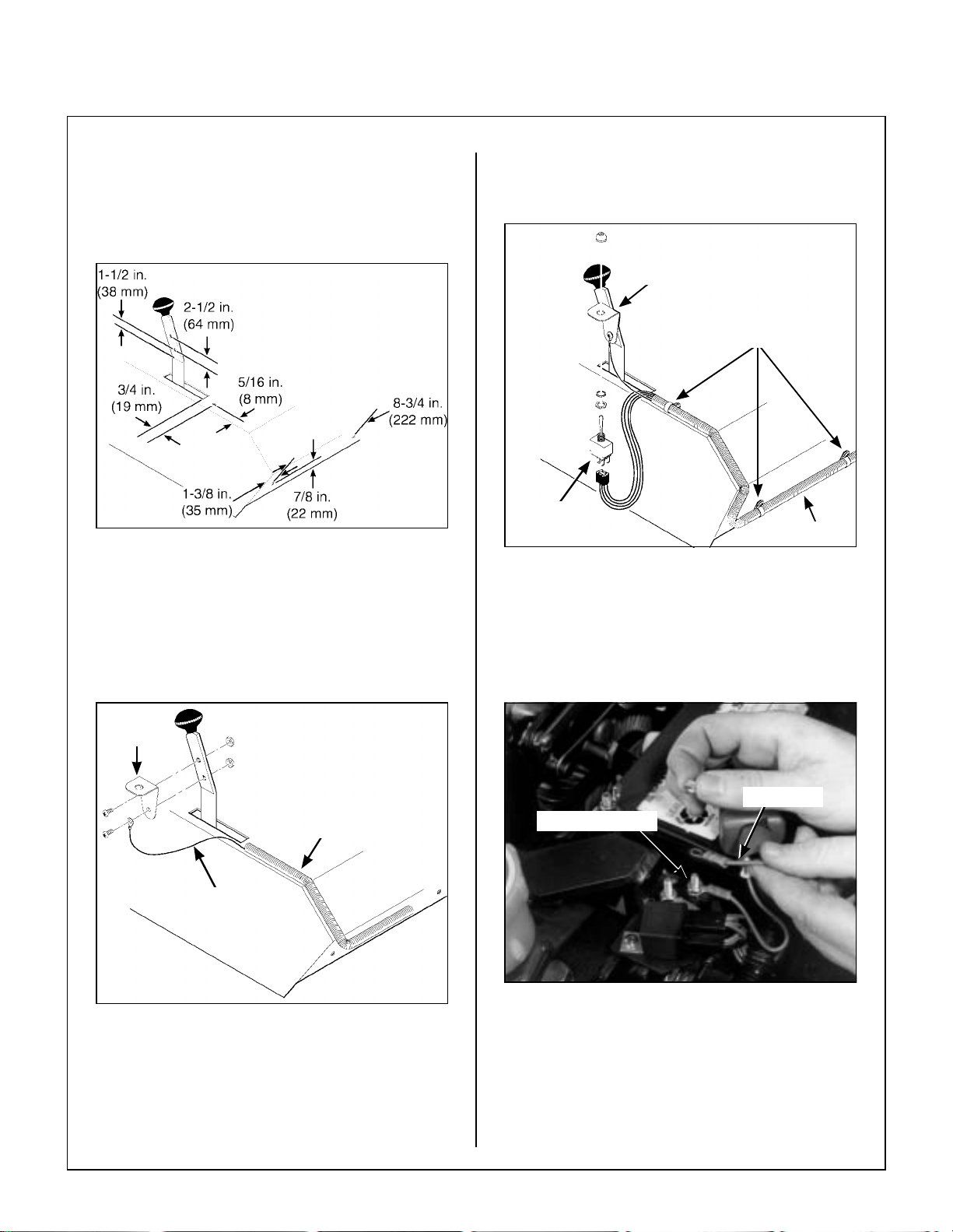
Implement Hitch Wiring
1. Drill five (5) 13/64 in. (5 m m) diame ter holes in
the tractor, two in the FSC lever and three in the
body, as shown in the illustration.
Drill Holes for Implement Hitch Wiring
2. Attach the toggle switch mounting bracket on
the FSC lever using two (2) 10-24 x 1/2 in. bolts
and Keps nuts. Connect the green ground wire
from the actuator wir ing harness to one o f the
bolts of the switch mounting bracket.
4. Attach the toggle switch to the mounting bracket, placing the switch terminals toward the front
of the mower.
Mounting Bracket
Wiring Clamps
Switch
Terminals
Attach Wiring Harness and Toggle Switch
5. On Models MC, MDD/MDG, and MT, connect
the harness red wire to the load side of the ci rcuit breaker mounted on the bracket behind the
battery.
Harness
Mounting
Bracket
Wiring
Harness
Ground
Wire
Attach Toggle Switch Mounting Bracket
3. Install the wiring harness to the tractor body using the three wiring clamps, three 10-24 x 3/8 in.
bolts and Keps nuts.
Red Wire
Circuit Breaker
Connect Harness Wire to Circuit Breaker
IMPORTANT: For all 1987-1997 Model MC
tractors (with Kohler Magnum engine), connect
the harness red wire to the free connector of the
PTO clutch switch red wire. Refer to Implement
Hitch Wiring Diagram illustration.
20
Page 25

Assembly Instructions
6. Complete the wiring by connecting the wiring
harness ends to the toggle switch and to the actuator motor of the implement hitch.
Wire Harness
Connector
Complete Implement Hitch Wiring
7. Move the implement lift switch backward to
raise the implement hitch to the UP position .
8. Move the implement lift switch forward to lower
the implement hitch to the DOWN position.
9. Raise and lower the hitch a few times to check
the operation and make sure it moves smoothly.
If not, make sure the wiring harne ss ends are
connected properly and sec urely. Refer to Im-
plement Hitch Wiring Diagram illustration.
Actuator Motor
Connector
21
Page 26
Assembly Instructions
22
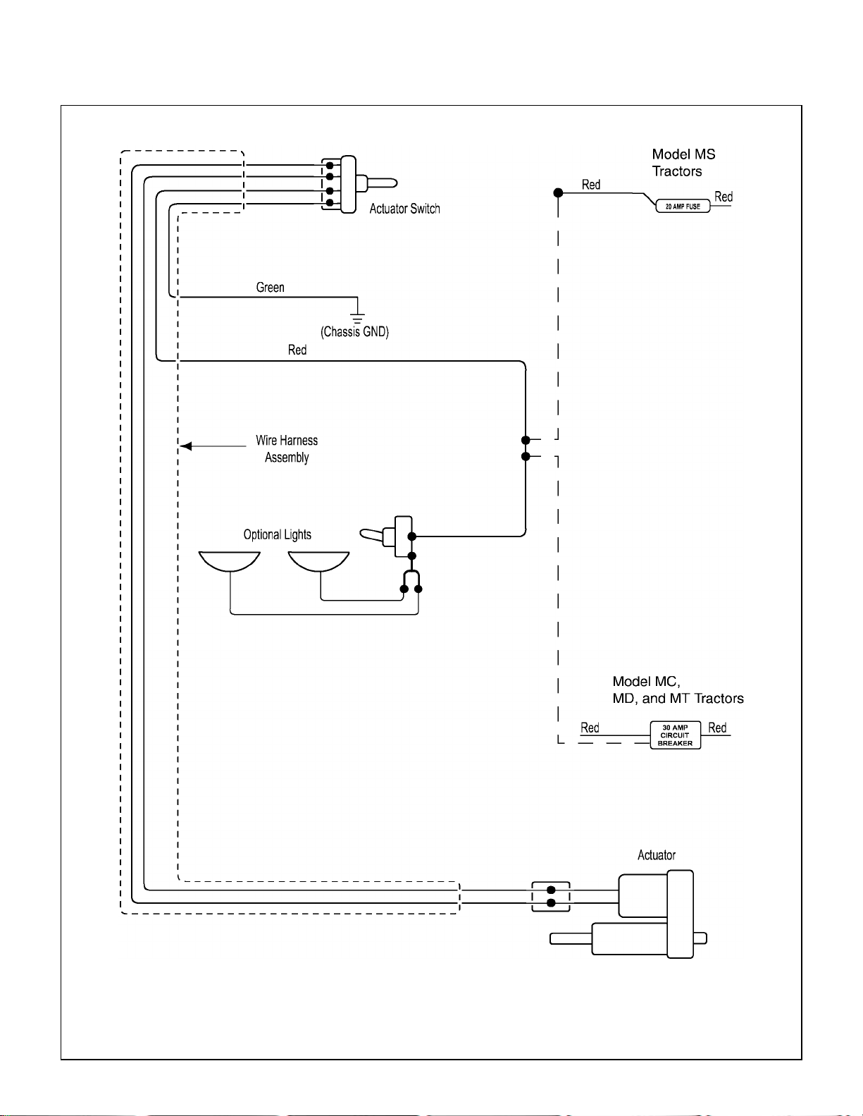
Implement Hitch Wiring Diagram
Page 27
Assembly Instructions
DOZER BLADE
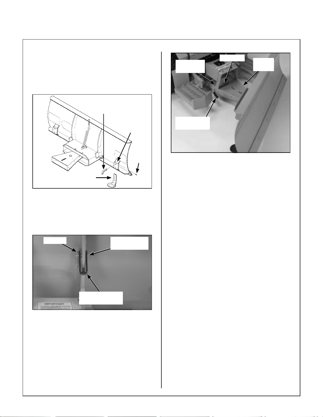
Dozer Blade Assembly
1. Insert the female quick hitch in to the hitch box
on the blade attachment.
2. Align the single hole at the end of the female
quick hitch with the single hole in the hitch box
and insert the pivot pin through both holes. Secure the pivot pin on the underside with a 1/4 x
1 in. roll pin.
Hitch Box
Pivot Pin
Female
Quick Hitch
Align Holes
Roll Pin
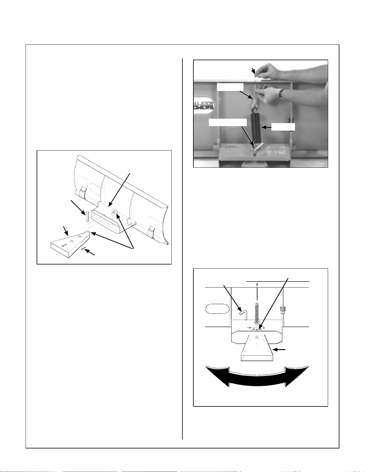
Nut
Eyebolt
Welded Tab
Attach Spring to Blade Assembly
5. Insert a 3/16 x 1 in. split spring pin into the angle
adjustment pin.
6. Rotate the female quick hitch to ob tain the required blade angle. Align the hole in the center
of the female quick hitch with one of the five (5)
holes in the hitch box, and insert t he angle adjustment pin thro ugh the to p an d b otto m h ole s.
Refer to Angle Adjustment Pin in Operating
Instructions.
Spring
Insert Female Hitch into Blade Attachment
3. Hook one end of the spring onto the welded tab
on the hitch box. Hook the eyebolt onto the free
end of the spr ing.
4. Insert the eyebolt up through the hole in the upper bend of the blade and secure it with a flat
washer and nu t. Adju st the le ngth of t he eyeb olt
according to the amount of sp ring tension required for safe operation. Refer to Trip Spring
in Operating Instructions.
Angle Adjustment Hole(s)Angle Adjustment
Pin
Female Quick
Hitch
Rotate Female Quick Hitch
For Required Blade Angle
Insert Adjustment Pin and Set Blade Angle
7. Install the two (2) skid shoes in the two brackets
on the rear outer edges of the blade.
23
Page 28
Assembly Instructions
8. Adjust the skid shoes to allow the required
clearance under the blade. Install a skid shoe
pin in each shoe and lock in place with a 4 mm
x 80 mm hairpin. Refer to ADJUSTMENTS of
Dozer Blade Skid Shoes in Maintenance In-
structions.
Skid Shoe
Pin
Skid Shoe
Bracket
Hairpin
Skid Shoe
Install Skid Shoes
Male Quick
Linchpin
Hitch
Hitch Locking
Lever
Attach Blade to Tractor
2. To install the optional tire chains:
a. Remove the tractor wheels.
b. Attach the tire chains to the wheels.
Female
Hitch
9. Install the trip spring lockout bracket in the upper hole behind the blade using the lockout pin
and hairpin.
Hairpin
Trip Spring
Lockout Bracket
Install Trip Spring Lockout Bracket
Dozer Blade Installation
1. Insert the male quick hitch section of the implement hitch into the female hitch of the blade.
Lock in place by moving the hitch locking lever
fully forward to the LOCKED position. Secure
the male qu ick hit ch la tch wi th th e linc hpi n. Refer to Hitch Locking Lever in Operating In-
structions.
Lockout Pin
in Upper Hole
c. Place the wh eel spacer plates on the lug
bolts. The wheel spacer plates provide
clearance for the chains bet ween the tires
and the tractor body.
d. Place the wheels back on the tractor.
e. Reinstall and tighten the lug bolts.
ROTARY BROOM
Rotary Boom Installation
1. Insert a parking stand into each stand su pport
bracket from the underside. Install a 5/32 x 1-1/
4 in. cotter pin in the upper hole of each parking
stand. Set the parking stands in their most ex-
tended position and secure each stand with
a 4 mm x 80 mm hairpin.
2. Check the pivot lock pin and mak e sure it is in
the innermost position to prevent bulking of
the female hitch member, and to facilitate quick
hitch attachment.
24
Page 29

Assembly Instructions
Stand Support
Bracket
Hairpin
Parking Stand
Prepare Rotary Broom for Installation
3. Attach the female broom driveline half (with
quick connect yoke ) over the male broom driv eline half. Set the driveline on its support.
NOTE: Driveline sliding surfaces must be
greased.
Reduction
Shaft
Male Quick
Hitch
Hitch Locking
Lever
Attach Broom to Implement Hitch
5. Connect the broom driveline to the tractor PTO
shaft by sliding back the l ocking collar on the
yoke, then push the y oke over the PTO shaft
until the locking collar snaps back fully. Make
sure the driveline is well secured at both ends.
Female Hitch
Drive Shaft
Yoke
Assemble Rotary Broom Driveline
4. Insert the male quick hitch section of the implement hitch into the female quick hitch of the rotary broom and place the male quick hitch lever
fully forward to the LOCKED position. Secure
the male qu ick hit ch la tch wi th th e linc hpi n. Refer to Hitch Locking Lever in Operating In-
structions.
DANGER
This shaft turns a t very high RPM. If the
collar is not locked to the PTO shaft at the
tractor end, or if the yoke at the broom
end is not secured properly, the driveline
can fly loose with gr eat force capable of
causing serious injury or death.
PTO Shaft
Locking Collar
Yoke
Connect Broom Driveline to Tractor PTO Shaft
25
Page 30

Assembly Instructions
6. Remove the hairpin from the welded sleeve on
the right hand side of the broom mounting
bracket. Carefully pull out the stopper pin to its
most extended position and lock in place with
the hairpin.
Welded Sleeve
Hairpin
Stopper Pin
Lock Stopper Pin in Place
8. Retract the parking stands and secure with the
hairpins prior to operation.
9. To install the optional tire chains:
a. Remove the tractor wheels.
b. Attach the tire chains to the wheels.
c. Place the wh eel spacer plates on the lug
bolts. The wheel spacer plates provide
clearance for the chains bet ween the tires
and the tractor body.
d. Place the wheels back on the tractor.
e. Reinstall and tighten the lug bolts.
10. For GHS (Grass Handling System) equipped
Walker tractors, install a blow er inta ke c over in
the blower intake tube. The cover “unloads” the
blower and seals the intake to effectively eli minate power loss and noise whe n the blower is
not being used.
Blower Intake
Cover
NOTE: The pin in the innermost position is used
to prevent the female hitch on the broom from
being pulled up by the brush ground contact
adjustment spring, thus facilitating mounting and
dismounting of the broom.
7. Adjust brush ground contact by threading knob.
Refer to Ground Contact Knob in Operating
Instructions.
Ground Contact Knob
Adjust Brush to Ground Contact
GHS Blower Intake Cover
1 1. For stability of the tractor when transporting with
the rotary broom in raised position, approximately 80 lb (36 kg) of counterweight should be
installed on the tail of the tr actor. Optional tail
weights for the various tractor models are available from your Walker dealer or a sandbag or
similar weight may be used.
Optional Gauge Wheel Installation
NOTE: Gauge wheels are required for lawn
work or heavy loads.
26
Page 31

Assembly Instructions
1. Remove the pin and hai rpin from each gauge
wheel. Select the required number of spacer
sleeves to remain on t he bottom porti on of the
gauge wheels. Refer to ADJUSTMENTS of
Rotary Broom Gauge Wheels in Maintenance
Instructions.
2. Remove the parking stands and repla ce them
with the gauge wheels. Place the remaining
spacer sleeve(s) over the gauge wheels on the
upper part of the stand supports, and secure the
gauge wheels with the pins and hairpins.
Pin
Spacer
Sleeves
Optional Gauge Wheel Installation
Hairpin
Support
Gauge
Wheel
Hand
Guard
Chute Base
Ring
Stand
Install Hand Guard on Chute
2. Remove the bushing support from the chute
base lip and discard the existing bolt (refer to In-
stall Rotation Worm Assembly photo).
3. Place the plastic anti-friction insert over the
chute base (placing the nipple on the upper side
towards the center of th e fan housing). Only
one position provides a perfect fit. Apply grease
on top of the insert where it will contact the
chute base.
Apply Grease
TWO-STAGE SNOWBLOWER
Snowblower Assembly
1. Install the hand guard on the chute, with the top
section inside the chute and the bottom section
outside the chute base ring. Place two (2) 1/4 x
3/4 in. bolts through the chute and the hand
guard. Secure wit h a flat wash er, lock washer,
and nut. Position the bo lt wit h th e h ead on th e
outside of the chute and the nut on the inside.
Torque both bolts to 10 ft-lb. (13.6 N·m).
Nipple
Install Plastic Insert over Chute Base Lip
4. Insert the 1-5/16 in. (33 mm) plastic bushing into the tube weldment.
27
Page 32

Assembly Instructions
5. Insert the 1-11/16 in. (43 mm) plastic bushing into the bushing su pport and place th is over the
shaft on the rotation worm.
6. Install the rotation worm assembly through the
tube weldment with the attaching plate of the
support on the underside of the chute base lip.
Tube
Weldment
Rotation
Worm
Bushing Support
With Attaching Plate
Install Rotation Worm Assembly
7. Install the chute over the pl astic insert and secure with four retaining plates, using two (2) 1/4
x 1/2 in. bolts, lock washers, and nuts in each of
the three (3) standard retaining plates, and two
(2) 1/4 x 3/4 in. bolts, lock washe rs and nu ts in
the rear right retaining plate which also secures
the support. Torque all bolts to 10 ft-lb. (13.6
N·m).
Bushing
8. Insert two (2) 5/16 x 1 in. carriage bolts through
each of the skid shoes from inside the bend.
Place a flat washer, lock washer, and nut loosely on each bolt and place the bolt heads through
the round holes in the outer ends of the bottom
angle of the sno wblower body. Adjust the sk id
shoes to allow the required clearance under the
cutting edge. Slide the square shank portion of
the bolt head into the slot and torque to 19 ft- lb
(25.8 N·m). Refer to ADJUSTMENTS of Two-
Stage Snowblower Skid Shoes in Mainte-
nance Instructions.
Snowblower
Housing
Skid Shoe
Carriage Bolts
Install Skid Shoes
28
Chute
Retaining
Plate
Install Chute over Plastic Insert
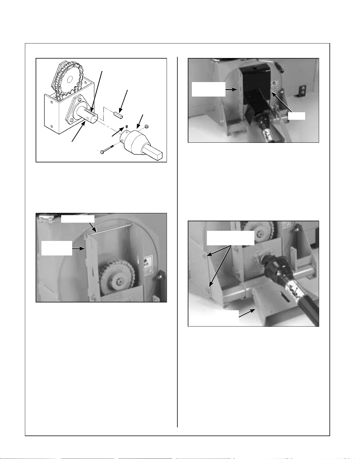
Snowblower Installation
1. Thoroughly clean the drive shaft yoke and install
a 1/4 x 1/4 x 1-1/4 in. key in the reduction shaft
keyway.
2. Slide the drive shaft yoke over the reduction
shaft.
3. Secure the yoke to the reduction shaft with a 1/4
x 2-1/2 in. bolt and nylon locknut. Tighten the
nut and the 3/8 x 3/8 in. allen set screw securely
over the key in the yoke.
Page 33
Assembly Instructions
Keyway
1/4 x 1/4 x
1-1/4 in. Key
Set Screw
Reduction
Shaft
Reduction
Box Cover
Drive
Shaft Yoke
Bolt
Install Reduction Box Cover
Attach Drive Shaft Yoke to Reduction Shaft
4. Install one 1/4 x 7-1/2 in. bolt through the upper
set of holes in the reduction box and secure
loosely with a lock washer and nut.
Install Bolt
Reduction
Box
Install Bolt in Reduction Box
5. Hook the reduction box cover over the bolt and
secure the cover with a second 1/4 x 7-1/2 in.
bolt, lock washer, and nut through the lower set
of holes in the reduction box. T orque both bolts
to 10 ft-lb (13.6 N·m).
6. Attach the female portion of the hitch to the
snowblower using one 3/8 x 1 in. bolt in the upper hole of each side, placing the bolt he ad on
the outside, with a flat washer, lock washer , and
nut on the inside. Use one 1/2 x 1 in. bolt, lock
washer and nut in the bottom hole of each side.
Tighten all four (4) bolts securely.
Bolt Heads On
Outside of Hitch
Female
Hitch
Mount Female Hitch to Snowblower
7. Insert the male quick hitch section of the implement hitch into the female hitch of the snowblower and lock in pla ce by moving the hitch
locking lever fully forward to the LOCKED position. Secure the latch with the linchpin. Refer
to Hitch Locking Lever in Operating Instruc-
tions.
8. Grease the drive shaft sliding surfaces and slide
the male shaft inside the female tube.
29
Page 34

Assembly Instructions
Clevis
Female
Hitch
Male Quick
Hitch
Hitch Locking
Lever
Attach Snowblower to Implement Hitch
9. Attach the driveline quick lock coupler to the
tractor PTO.
WARNING
This shaft turns at high RPM. If the collar
is not locked to the shaft at the tractor
end, or if the yoke at the blower end is not
secured properly, the drive shaft can fly
loose with great force, capable of causing
serious injury or death.
Parallel Bar
Clevis
Attach Parallel Bar to Female Hitch
1 1. Insert the rotation handle into the rotation worm.
Align the holes and lock in place with a 1/4 x
1 in. socket head cap screw and nylon locknut.
12. Install the plastic handle grip on the chute rotation handle.
Rotation
Handle
30
Driveline Coupler
Tractor PTO
Connect Driveline Coupler to Tractor PTO
10. Attach the parallel b ar to the female hitc h and
the implement adaptor using the two clevises
and spring clips.
Insert Rotation Handle into Rotation Worm
13. To install the optional tire chains:
a. Remove the tractor wheels.
b. Attach the tire chains to the wheels.
c. Place the wh eel spacer plates on the lug
bolts. The wheel spacer plates provide
clearance for the chains bet ween the tires
and the tractor body.
d. Place the wheels back on the tractor.
e. Reinstall and tighten the lug bolts.
Page 35

Assembly Instructions
14. For GHS (Grass Handling System) equipped
Walker tractors, install a blower intake cover in
the blower int ake tube. The cover “unloa ds” the
blower and s eal s the i ntake to effectively el im inate power loss and no ise when the blower is
not being used. Refer to GHS Blower Intake
Cover illustration for ROTARY BROOM in this
section.
15. For stability of the tractor when transporting with
the snowblower in raised position, approximately 80 lb (36 kg) of c ounterweight shou ld be installed on the tail of the tractor. Optional tail
weights for the various tractor models are available from your Walker dealer or a sandbag or
similar weight may be used.
DEBRIS BLOWER
Debris Blower Installation
The debris blower is shipped completely assembled
except for the driveline, which must be connected to
the input shaft.
5. Reinstall the belt guard by reversing the removal procedure.
6. Insert the male quick hitch section of the implement hitch into the female hitch of the debris
blower and lock in pla ce by moving the hitch
locking lever fully forward to the LOCKED position. Secure the latch with the linchpin. Refer
to Hitch Locking Lever in Operating Instruc-
tions.
Linchpin
Hitch Locking
Lever
Female
Quick Hitch
1. Remove the belt guard from the debris blower
housing by removing the two (2) cover pins and
hairpins securing it to the housing.
2. Thoroughly clean the debris blower input sha ft
and install a 1/4 x 1/4 x 1-1/4 in. key in the input
shaft keyway.
3. Thoroughly clean the insi de of the tractor PTO
shaft and align the PTO shaft key way with the
key in the input s haft keyway.
4. Secure the PTO shaft to the input shaft with a
1/4 x 2-1/2 in. bolt and nylon loc knut. Tighten
the locknut and the set screw over the key.
Shear
bolt
Set Screw
Tractor
PTO
Attach Debris Blower to Implement Hitch
7. To install the optional tire chains:
a. Remove the tractor wheels.
b. Attach the tire chains to the wheels.
c. Place the wh eel spacer plates on the lug
bolts. The wheel spacer plates provide
clearance for the chains bet ween the tires
and the tractor body.
d. Place the wheels back on the tractor.
e. Reinstall and tighten the lug bolts.
8. For GHS (Grass Handling System) equipped
Walker tractors, install a blow er inta ke c over in
the blower intake tube. The cover “unloads” the
blower and seals the intake to effectively eli minate power loss and noise whe n the blower is
not being used. Refer to GHS Blower Intake
Cover illustration for ROTARY BROOM in this
section.
Attach Tractor PTO to Debris Blower Input Shaft
31
Page 36

Assembly Instructions
9. For stabili ty of th e tractor when tran sporting w ith
the debris blower in raised position, approximately 80 lb (36 kg) of counterweight should be
installed on the tail of the trac tor. Optional tail
weights for the various tractor models are available from your Walker dealer or a sandbag or
similar weight may be used.
PREOPERATING CHECKLIST
Before operating any of the imple ments for the first
time, and as a routine before dai ly operations, it is
important to make sure the machine is properly prepared and ready for operation. The following is a list
of items to be che cked. (For machines with frequent operation, some of these items will not need to
be checked every day, but the operato r should be
aware of the condition of each.)
CHECK TRACTOR PREOPERATING
CHECKLIST
Refer to the appropriate Tractor Owner’s Manual.
CHECK GAUGE WHEEL OR SKID SHOE
ADJUSTMENT
Implement Hitch
CHECK LIFT SWITCH OPERATION
Raise and lower the imp lement hitch to make sure
the lift switch and linear actuator operate properly.
CHECK HITCH LOCKING LEVER
Lock and unlock t he male hitch to make sure the
locking mechanism functions properly.
Refer to Hitch Locking Lever in Operating Instruc-
tions.
Dozer Blade
CHECK CUTTING EDGE
• Make sure the c utting edge is not nicked, bent
or worn.
Refer to REPLACING/REPAIRING of Dozer Blade
Cutting Edge in Maintenance Instructions.
CHECK TRIP SPRING
Refer to ADJUSTMENTS of Dozer Blade Skid
Shoes in Maintenance Instructions.
Refer to ADJUSTMENTS of Rotary Broom Gauge
Wheels in Maintenance Instructions.
Refer to ADJUSTMENTS of Two-Stage Snow-
blower Skid Shoes in Maintenance Instructions.
Refer to ADJUSTMENTS of Debris Blower Front
Gauge Wheel in Maintenance Instructions.
CHECK OPTIONAL TIRE CHAINS
Tire chains should always be used whe n operating
the machine in icy conditions. If the tractor is
equipped with the optional tire chains, make sure
the chains are in good c ondition and are installed
properly.
CHECK TRACTOR TAILWEIGHT
Make sure 80 lb (36 kg) weight has been installed on
rear of tractor.
• Check trip spring tension.
Refer to Trip Spring in Operating Instructions.
• Check trip spring lockout bracket.
Refer to Normal Operat ion or Rigid Blade Operation in Operating Instructions.
CHECK SWIVEL ADJUSTMENT
Refer to Angle Adjustment Pin in Operating In-
structions.
Rotary Broom
CHECK BRUSH
• Make sure the brush is clear of snow and/or
ice.
• Make sure the brush is free to rotate.
• Check that the bristles are in good condition
and are not worn or bent.
32
Page 37

Assembly Instructions
CHECK BROOM ANGLE ADJUSTMENT
Refer to Angle Adjustment L ever in Operating In-
structions.
CHECK DRIVE CHAIN
Refer to LUBRICATION for Rotary Broom Drive
Chain in Maintenance Instructions.
Refer to ADJUSTMENTS of Rotary Broom Drive
Chain T ension in Maintenance Instructions.
CHECK GEARBOX
Refer to LUBRICATION for Rotary Broom Gear-
box in Maintenance Instructions.
CHECK SIDE TO SIDE LEVEL ADJUSTME NT
Refer to ADJUSTMENTS of R otary Broom Brush
Leveling in Maintenance Instructions.
CHECK BRUSH TO GROUND CONTACT
PRESSURE ADJUSTMENT
Refer to Ground Contact Knob in Operating In-
structions.
CHECK CHUTE AND DEFLECTOR
• Make sure the chute and deflector are not
clogged with snow and/or ice.
• Turn the chute rotation handle and rotate the
chute. The chute should rotate freely.
• Use the deflector position control knobs and
raise and lower the deflector. The deflector
should move freely.
CHECK GEARBOX
Refer to LUBRICATION for Two-St age Snowblow-
er Gearbox in Maintenance I nstructions.
CHECK REDUCTION CHAIN
Refer to LUBRICATION for Two-St age Snowblow-
er Reduction Chain in Maintenance Instructions.
Refer to ADJUSTMENTS for Two-Stage Snow-
blower Reduction Chain Tension in Maintenance
Instructions.
Debris Blower
CHECK CHUTE AND DEFLECTOR
Two-Stage Snowblower
CHECK CUTTING EDGE
• Make sure the cutting edge is n ot nicked, bent
or worn.
Refer to REPLACING/REPAIRING of Two-Stage
Snowblower Cutting Edge in Maintenance Instruc-
tions.
CHECK AUGER
• Make sure the auger is clear of snow and/or
ice.
• Make sure the auger is free to rotate.
• Check that the auger flighting and paddle
blades are in good condition and not bent.
• Make sure the chute and deflector are not
clogged with leaves and/or debris.
• Turn the chute rotation handle and rotate the
chute. The chute should rotate freely.
• Use the deflector position control knob and
raise and lower the deflector. The deflector
should move freely.
CHECK GAUGE WHEEL TIRE PRESSURE
• Make sure the tire pressure is 20 PSI (137 kPa).
INSPECT DRIVE BELT
Refer to ADJUSTMENTS of Debris Blower Drive
Belt Tension in Maintenance Instructions.
CHECK BLOWER FAN
• Make sure the fan is clear of debris.
• Make sure the fan is free to rotate.
• Check that the fan blades are in good condition
and not bent.
33
Page 38

Operating Instructions
Snow Removal
WARNING
Foreign objects in snow may be thrown
farther than the snow. Use the slowest
brush speed that will perform the job.
Stay aware of the broom discharge direction at all times.
Rotate Chute
Clockwise
Rotate Chute
Counterclockwise
1. The rotary broom works best on snow depths of
4 in. (10 cm) or less. Larger amounts of snow
can be moved if the ground speed is reduced.
2. T o avoid snow being blown back onto the tractor
and operator, sweep with the wind blowing in
the direction of broom discharge.
Lawn Thatching and Leaf Raking
CAUTION
Optional gauge wheels must be installed
to perform these types of operation in order to avoid excessive brush ground c ontact.
1. Bristles should barely touch the ground for lawn
thatching, and barely touch the grass in leaf raking operations.
2. Slower brush speed and ground speed are
more adequate for lawn thatching. This will prevent “bouncing” which could damage the lawn
due to excessive ground contact.
Chute Rotation
Handle
Chute Rotation Handle
Deflector Position Control Knobs
Set the angle of the deflecto r according to the distance the snow must be thr own. To adjust the de flector angle, loosen the two knobs on the sides of
the deflector, slide the deflector to the required angle, and securely retighten the two knobs.
Deflector Position
Control Knobs
38
3. Minimize dust by sweeping when moisture is
high (but not wet) whenever possible.
TWO-STAGE SNOWBLOWER CONTROLS
Chute Rotation Handle
The chute rotation handle is located on the rear of
the snowblower head, on the lo wer RH side of the
discharge chute. The chute rotates in a 228 degree
arc, by cranking the rotation handle. Turning the
handle clockwise rotates the chute clockwise.
Turning the handle count erclockwise rotates the
chute counterclockwise.
Deflector Position Control Knobs
TWO-STAGE SNOWBLOWER OPERATION
CAUTION
Before operating the snowblower, read
and understand all Safety Instructions and
Operating Instructions.
Raising and Lowering the Snowblower Refer to Implement Lift Switch in this section.
Page 39

Operating Instructions
Engaging the Snowblower
1. Make sure that the snowblower is clear of snow
and/or ice before engaging the snowblower.
2. Make sure that the auger and fan operate freely.
3. Check the oil level in th e worm gearbox an d if
necessary, add SAE 90 E.P. (Extreme Pressure) oil. Make sure the oil level is up to the side
plug. (Refer to LUBRICATION of Two-Stage
Snowblower Gearbox in Maintenance Instructions.)
4. Check the three (3) shear bolts, one on each auger section, and one between the fan and gearbox for proper tight ness, approximately 8 ft-lb
(11 N·m).
5. Adjust the snowblower so that it runs level.
6. Set the engine throttle at about 1/3 speed. DO
NOT attempt to engage the PTO clutch at
high engine speeds. This will drastically short-
en drive belt life . Use only moderate engine
speed when engaging the PTO clutch.
DANGER
If the auger strikes a solid object or the
machine begins to vibrate abnormally , immediately disengage the PTO clutch, stop
the engine, and wait for all moving parts
to stop. Disconnect the fuel solenoid wire
[diesel engines] or the spark plug wire(s)
[gasoline engines] to prevent accidental
starting. Thoroughly inspect the snowblower and repair any damage before restarting the engine and operating the
machine. Make sure auger blades are in
good condition and all bolts are tight.
7. Pull the PTO clutch lever SLOWLY to engage
the snowblower.
NOTE: For cold weather operation, allow sufficient time for the snowblower components (i.e.,
gearbox oil) to warm up before beginning to blow
snow.
DANGER
A safety interlock switch (seat switch) will
cause the engine to stop if the PTO clutch
is engaged and the operator is not in the
seat. The function of this switch should
be checked by the operator raising off the
seat and engaging the PT O clutch; the e ngine should stop. If the switch is not
working, it should be rep aired or replaced
before operating the snowblower. DO
NOT disconnect the safety switche s; they
are for the operator’s protection.
IMPORTANT: DO NOT engage the PTO clutch
when transporting the machine. DO NOT engage
the PTO clutch with the PTO shaft disconnected
(the snowblower removed from the tractor).
Engaged
Position
PTO Clutch Engaged
Disengaged
Position
PTO Clutch Disengaged
Recommendations For Snowblowing
IMPORTANT: Operate the engine at full speed
when snowblowing, to allow the eng ine to produce
full horsepower and to increase efficiency of the engine cooling system.
39
Page 40

Operating Instructions
• When operati ng on a slope, re duce speed and
use caution to start, stop, and maneuver. Avoid
sharp turns or sudden changes in direction.
• When blowing through deep snow drifts, le t the
snowblower work its way through the drifts. For best
results, raise the snowblower and remove a top layer of snow, then pass through the area a second
time to remove the remaining snow.
• When snowblowing, operate the engine at or near
full throttle for the best snowblowin g action. The
engine is designed to be operated at full speed.
• Use optional tire chains or optional all-terrain tires
to improve traction.
• Disengage the PTO clutch to stop the snowblow-
er when driving the machine but not blowing snow.
• Avoid damage to property and extra snowblowing
work by carefully choosing the direction to move
the snow. Orient the blow er a w ay fr om p eop le and
property due to the possibility of thrown objects.
• T o momentarily increase traction in case the drive
wheels are slipping , use the lift switch to rai se the
snowblower slightly and transfer extra weight on the
drive wheels.
Throw Snow to One Side
Use the following pattern where snow can be thrown
to both sides. Start in the middle with the blower
spout directed to either the right or left. Drive
from one end to the other in an outward spiral,
without changing the position of the blower
spout to throw snow to both sides.
Removing Snow
DANGER
DO NOT blow snow with bystanders in the
area (especially children or pets).
A definite operating pattern is required to thoroughly
clean snow from an area. Each pattern described
below clears all the snow in one pass (of the pattern)
and prevents throwing snow in unwanted places.
IMPORTANT: DO NOT use the snowblower as a
dozer blade to push snow. Let the snowblower work
its way through deep snow. If the tractor is driven
forward into snow too fast, the snowblower may
become overloaded and clog.
Use the following pattern where snow can be thrown
only to one side. Start on the side farthest from
where the snow will be thrown. At the end of the
first pass, rotat e the blower spout 180 degrees for
the return pass. At the end of each following pass,
rotate the spout 180 degrees to keep throwing snow
in the same direction.
Throw Snow to Both Sides
Clogging Checklist
In case of clogging, the snow throwing action will decrease and finally stop. When this occurs, disengage the PTO clutch, stop the engine, disconnect
the fuel solenoid wire [diesel engines] or spark plug
wire(s) [gasoline eng ines], and rem ove the ignition
key. Make sure all movement has stopped be-
fore attempting to unclog.
40
Page 41

Operating Instructions
DANGER
DO NOT attempt to unclog the snowblower or make any adjustments with the tractor engine running. Disengage the PTO
clutch, stop the engine, and remove the
ignition key.
DANGER
Chute Rotation
Handle
NEVER place hands in the blower spout.
DO NOT use hands or feet to unclog the
snowblower. Use a short stick or si milar
tool to remove any clogged material.
The following list of items should be checked if a pattern of clogging begins to develop. All of these items
are capable of causing clogging.
• Check that the inside of the snowblower housing
is clean and free of snow and/or ice buildup.
• Check that the auger is in good condition and not
bent, both the auger f lighting and the center paddles.
• Check the insi de of t he bl ower s pout for smooth-
ness and freedom of obstruction.
Remember, anything that restricts airflow or material flow along the e ntire path from the auger to the
blower spout can cause clogging.
DEBRIS BLOWER CONTROLS
Chute Rotation Handle
Chute Rotation Handle
Deflector Position Control Knob
Set the angle of the deflector ac cording to the distance the debris must be thrown. To adjust the deflector angle, loosen the knob on the RH side of the
deflector, slide the deflector to the required angle,
and securely retighten the knob.
Deflector Position
Control Knob
Deflector Position Control Knob
DEBRIS BLOWER OPERATION
The chute rotation handle is lo cated on the rear of
the debris blower, on the upp er RH side of the impeller housing. The chut e rotates in a 230 degree
arc, by cranking the rotation handle. Turning the
handle clockwise rotates the chute clockwise.
Turning the handle counterclockwise rotates the
chute counterclockwise.
CAUTION
Before operating the debris blower, read
and understand all Safety Instructions and
Operating Instructions.
Raising and Lowering the Debris Blower
Refer to Implement Lift Switch in this section.
41
Page 42

Operating Instructions
Engaging the Debris Blower
1. Set the engine throttle at about 1/3 speed. DO
NOT attempt to engage the PTO clutch at
high engine speeds. This will drastically short-
en drive belt life . Use only moderate engine
speed when engaging the PTO clutch.
2. Pull the PTO clutch lever SLOWLY to engage
the debris blower.
NOTE: For cold weather operation, allow sufficient time for th e debris blower com ponents to
warm up before beginning to blow debris.
WARNING
A safety interlock switch (seat switch) will
cause the engine to stop if the PTO clutch
is engaged and the operator is not in the
seat. The function of this switch should
be checked by the operator raising off the
seat and engaging the PT O clutch; the e ngine should stop. If the switch is not
working, it should be rep aired or replaced
before operating the debris blower. DO
NOT disconnect the safety switche s; they
are for the operator’s protection.
IMPORTANT: DO NOT engage the PTO
clutch when transporting the machine. DO NOT
engage the PTO clutch with the PTO shaft
disconnected (the debris blower removed from
the tractor).
Recommendations For Operating the Debris Blower
IMPORTANT: Operate the engine at full speed
when operating the debr is blower, to allow the engine to produce full horsepow er a nd to i nc reas e efficiency of the engine cooling system.
• When operati ng on a slope, re duce speed and
use caution to start, stop, and maneuver. Avoid
sharp turns or sudden changes in direction.
the debris. Orient the blower away from people and
property due to the possibility of thrown objects.
• T o momentarily increase traction in case the drive
wheels are slipping, use the lift switch to rais e the
debris blower slightly and tr ansfer extra weight on
the drive wheels.
STOPPING THE MACHINE
1. Slow the engine to idle; put the throttle in the
IDLE position.
2. Pull the steering levers to the NEUTRAL posi tion and then move the FSC lever bac kward to
the NEUTRAL-PARK position.
3. Disengage the PTO clutch.
IMPORTANT: DO NOT disengage the PTO
clutch with high engine speed (above 1/2 throttle) since the brake action on the PTO drive will
cause premature wear of the brake band.
WARNING
A brake stops the machine from freewheeling within five (5) seconds after disengaging the PTO clutch. If the brake
system malfunctions and the machine
does not stop within five (5) seconds, the
brake should be adjusted or repaired before operating the machine. Refer to the
appropriate Tractor Owner’s Manual for
adjustment procedures.
4. Turn the ignition switch OFF.
WARNING
Remove the key from th e ignition switch
when leaving the machine unattended.
This will prevent children and inexperienced operators from starting the engine.
5. Engage the parking brake.
42
• Use optional tire chains or optional all-terrain tires
to improve traction.
• Disengage the PTO clutch to stop the debris
blower when driving the machine but no t operating
the debris blower.
• Avoid damage to property and extra cleaning
work by carefully choosing the direction to move
IMPORTANT: The hydrostatic transmissions
lock to prevent the machine fr om rolling freely
with the engine stopped. Howeve r, if the machine is parked on a slope, it is necessary to
ENGAGE the parking BRAKE to prevent the
machine from creep ing. This is due to a small
amount of slippage in t he h yd ro static tr an sm is sions, especially when transmission fluid is
warm.
Page 43

Maintenance Instru ctions
MAINTENANCE SCHEDULE CHART - RECOMMENDED SERVICE INTERVALS - IMPLEMENTS
CAUTION
Maintenance procedures requiring special training or
tools should be performed by a trained technician.
Model Service Item Daily
Check Tire Chains (Optional) X 32
Check Gauge Wheels or Skid Shoes X 32
All Models:
Implement Hitch:
Dozer Blade:
Rotary Broom:
Check Tractor Tailweight X 32
Lubricate Grease Fittings and Oil Points X 45
Repaint Components/Parts X 70
Check Implement Lift Switch Operation X 32
Check Hitch Locking Lever Function X 32
Check Dozer Blade Cutting Edge Condition X 32
Check Dozer Blade Trip Spring Tension X 32
Check Dozer Blade Swivel Adjustm ent X 32
Check Rotary Broom Brush Condition X 32
Check Broom Angle Adjustment Lever X 33
Check Broom Side to Side Level Adjustment X 33
Check Rotary Broom Ground Contact Knob X 33
Check Rotary Broom Gearbox Oil Seals X 44
25
Hours Yearly
Reference
Page
Lubricate Rotary Broom Drive Chain X 44
Check Snowblower Auger Condition X 33
Check Snowblower Chute Rotation Handle X 33
Two-Stage
Snowblower:
Debris Blower:
Refer to the appropriate Tractor Owner’s Manual for complete information about Tractor Maintenance Items.
Check Snowblower Deflector Position
Control Knobs
Check Snowblower Scraper Blade Condition X 33
Check Snowblower Gearbox Oil Seals X 45
Lubricate Snowblower Reduction Chain X 45
Check Debris Blower Chute Rotation Handle X 33
Check Debris Blower Deflector Position
Control Knob
Check Debris Blower Gauge Wheel
Tire Pressure
Check Debris Blower Impeller Condition X 33
Check Debris Blower Drive Belt
Tension and Condition
X33
X33
X33
X33
43
Page 44

Maintenance Instru ctions LUBRICATION
LUBRICATION
WARNING
DO NOT attempt to lubricate the machine
with the tractor engine running. Disengage the PTO clutch, shut off the machine, and remove the ignition key.
Proper lubrication is an important maintenance procedure. It reduces wear and makes the machine
quieter and easier to operate.
Rotary Broom Gearbox
The gearbox is permanently lubricated (oil filled) and
sealed requiring no scheduled lubrication. However,
the gearbox oil seal(s) should be checked every 25
hours for indication of an oil leak. If an o il leak is
noted, replace the oi l se al a nd re lub ric ate the g ear box as follows:
1. Remove the gearbox following the procedure
described in REPLACING/REPAIRING the Ro-
tary Broom Gearbox in this section.
4. If the lubricant is flowing out of the plug hole, the
gearbox is full. Reinsert the plug. If no lubricant
flows out, add SAE E.P. (Extreme Pressure)
90W oil into the gearbox thr ough the pl ug hole
until it starts to flow out.
5. Wipe the threads of the gearbox plug before reinstalling.
6. Torque screws to 24 in-lb (2.7 N·m).
NOTE: In case the gearbox is completely
drained of oil, approximately 5 fl. oz. (15 cl) of oil
is required to refill the gearbox.
Rotary Broom Drive Chain
Lubricate the drive chai n every 25 hours. A light
penetrating oil or special purpose chain oil is recommended. Lubricate the drive chain as follows:
1. Remove the two (2) bolts fastening the chain
guard cover to the broom housi ng and remove
the cover.
Drive Chain
Dipstick Plug
Gearbox
Mounting
Bolt
Gearbox
Plug
Rotary Broom Gearbox with Cover Removed
2. Clean the area around the plug lo cated on th e
front of the gearbox.
3. Remove the gearbox plug on the gearbox.
Gearbox
Cover
Chain Guard BoltsChain Guard Cover
Remove Chain Guard Cover
2. Apply oil to the drive chain.
3. Reinstall the chain guard cover by reversing the
removal procedures.
44
Page 45

Maintenance Instru ctions LUBRICATION
Two-Stage Snowblower Gearbox
The gearbox is permanently lubricated (oil filled) and
sealed requiring no scheduled lubrication. However,
the gearbox oil seal(s) should be checked every 25
hours for indication of an oil leak. If an o il leak is
noted, replace the oil seal(s) and relubricate the
gear-box as follows:
1. Remove the gearbox following the procedure
described in REPLACING/REPAIRING the
Two-Stage Snowblower Gearbox in this section.
Two-Stage Snowblower Reduction Chain
Lubricate the reduction chain every 25 hours. A light
penetrating oil or special purpose chain oil is recommended. Lubricate the reduction chain as follows:
1. Remove the bolt fastening the reduction box
cover to the reduct ion box and remove the cover .
Reduction
Chain
Remove Reduction Box Cover
Lubricant
Plug
Snowblower Lubricant Plug Location
2. Clean the area around the lubric ant plug l ocated on the front of the gearbox.
3. Remove the lubricant plug on the gearbox.
4. If the lubricant is flowing out of the plug hole, the
gearbox is full. Reinsert the plug. If no lubricant
flows out, add SAE E.P. (Extreme Pressure)
90W lubricant into the gearbox through the plug
hole until it starts to flow out.
5. Wipe the threads of the gearbox plug before reinstalling.
6. Torque to 24 in-lb (2.7 N·m).
NOTE: In case the gearbox is completely
drained of oil, approximately 5 fl. oz. (15 cl) of oil
is required to refill the gearbox.
2. Apply oil to the reduction chain.
3. Adjust the chain if necessary. Refer to AD-
JUSTMENTS of Two-Stage Snowblower Reduction Chain Tension in this section.
4. Reinstall the reduction box c over by reversing
the removal procedures.
Grease Fitting and Oil Point Lubrication Lubricate the grease fittin gs and oi l po in ts after ev-
ery 25 hours of operation. Use SAE general pur-
pose lithium or molybdenum base grease for grease
fittings and light machine oil (SAE 10) to lubricate oil
points. Lubricate the locations shown in the Lu-
brication Points illustrations on the following
pages.
45
Page 46

Maintenance Instru ctions LUBRICATION
Ident Lubrication No.
No. L ocation Type Places
Implement Hitch
1 PTO Shield Hinge Oil 1
2 Hitch Locking Lever Pivot Oil 1
3 Mounting Tube Sockets Grease 2
4 Hitch Lift Crank Grease 1
Ident Lubrication No.
No. Location Type Places
5 Hitch Pivot Shaft Oil 1
6 Quick Hitch Latch Oil 1
NOTE: Tractor Lubrication Points are not shown here.
For Tractor Lubrication Points, refer to the appropriate Tractor OWNER’S MANUAL or IL-
LUSTRATED PARTS MANUAL.
46
Page 47
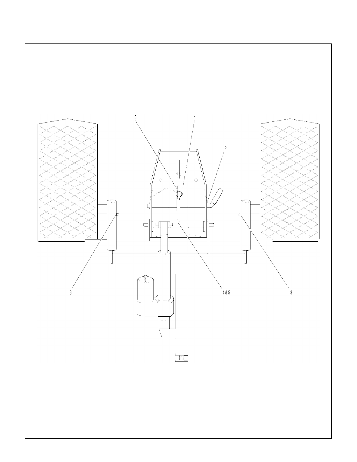
Maintenance Instru ctions LUBRICATION
Implement Hitch Lubrication Points
47
Page 48

Maintenance Instru ctions LUBRICATION
Ident Lubrication No.
No. L ocation Type Places
Dozer Blade
1 Cutting Edge Oil 1
2 Skid Shoe Brackets Grease 2
(Grease Slide Area)
3 Hitch Box Pin Oil 1
4 Trip Spring Lockout Bracket
Pivot Pin Oil 1
Ident Lubrication No.
No. Location Type Places
5 Angle Adjustment Pin Oil 1
6 Female Quick Hitch Pivot Pin Oil 1
NOTE: Tractor Lubrication Points are not shown here.
For Tractor Lubrication Points, refer to the appropriate Tractor OWNER’S MANUAL or IL-
LUSTRATED PARTS MANUAL.
48
Page 49

Maintenance Instru ctions LUBRICATION
Dozer Blade Lubrication Points
49
Page 50

Maintenance Instru ctions LUBRICATION
Ident Lubrication No.
No. L ocation Type Places
Rotary Broom
1 Chain Drive Sprocket Oil 1
2 Chain Drive Shaft Grease 1
3 Gearbox Oil
4 Wheel Brackets Grease 2
5 Angle Adjustment Lever Pivot Oil 1
6 Driv eline Grease 1
7 Driveline Support Pivot Oil 1
8 Angle Adjustment Plate Oil 1
9 Universal Joint Shaft Assembly Grease
(Grease Slide Area)
10 Ground Contact Knob Eyebolt Grease 1
11 Drive Chain Oil 1
* 1
** 1
Ident Lubrication No.
No. Location Type Places
* Gearboxes are permanently lubricated and
sealed requiring no scheduled lubrication.
Oil level should be chec ked onl y when an oil
leak is noted. Refer to Rotary Broom Gear-
box in this section.
** Grease every eight (8) hours.
NOTE: Tractor Lubrication Points are not shown here.
For Tractor Lubrication Points, refer to the appropriate Tractor OWNER’S MANUAL or IL-
LUSTRATED PARTS MANUAL.
50
Page 51

Maintenance Instru ctions LUBRICATION
Rotary Broom Lubrication Points
51
Page 52

Maintenance Instru ctions LUBRICATION
Ident Lubrication No.
No. L ocation Type Places
Two-Stage Snowblower
1 Auger Sections Grease 2
2 Gearbox Oil
3 Cutting Edge Oil 1
4 Skid Shoes Grease 2
5 Gearbox Shaft Oil 1
6 Rotation Worm Grease 1
7 Reduc tion Chain Oil 1
8 Sprockets Oil 2
9 Parallel Bar Pivot Pins Oil 2
10 Universal Joint Shaft Assembly Grease
(Grease Slide Area)
11 Rotation Handle Pivot Oil 1
* 1
** 1
Ident Lubrication No.
No. Location Type Places
12 Plastic Anti-Friction Insert Grease 1
13 Chute Knobs Grease 2
14 Deflector Slide Area Grease 1
* Gearboxes are permanently lubricated and
sealed requiring no scheduled lubrication.
Oil level should be chec ked onl y when an oil
leak is noted. Refer to Two-Stage Snow-
blower Gearbox in this section.
** Grease every eight (8) hours.
NOTE: Tractor Lubrication Points are not shown here.
For Tractor Lubrication Points, refer to the appropriate Tractor OWNER’S MANUAL or IL-
LUSTRATED PARTS MANUAL.
52
Page 53

Maintenance Instru ctions LUBRICATION
Two-Stage Snowblower Lubrication Points
53
Page 54

Maintenance Instru ctions LUBRICATION
Ident Lubrication No.
No. L ocation Type Places
Debris Blower
1 Front Gauge Wheel Grease 1
2 Plastic Anti-Friction Insert Grease 1
3 Air Blast N ozzle Oil 1
4 Sprockets Oil 2
Ident Lubrication No.
No. Location Type Places
5 Rotation Handle Grease
6 Universal Joint Shaft Assembly Grease
(Grease Slide Area)
* 2
* 1
* Grease every eight (8) hours.
NOTE: Tractor Lubrication Points are not shown here.
For Tractor Lubrication Points, refer to the appropriate Tractor OWNER’S MANUAL or IL-
LUSTRATED PARTS MANUAL.
54
Page 55

Maintenance Instru ctions LUBRICATION
Debris Blower Lubrication Points
55
Page 56

Maintenance Instru ctions REPLACING/REPAIRING
REPLACING/REPAIRING
WARNING
To prevent accidental engine starting
when replacing parts or repairing the
machine, remove the key from the ig nit ion
switch and disconnect the fuel solenoid
wire [diesel engines] or the spark plug
wire(s) [gasoline engines].
CAUTION
ALWAYS use genuine factory replacement
part s. Subs titut e parts CAN result in product malfunction and possible injury to the
operator and/or others.
Dozer Blade Cutting Edge
NOTE: The cutting edge of the dozer bla de is re-
versible and needs t o be re pl aced only when both
the top and bottom edges have worn.
Replace the dozer blade cutting edge as follows:
1. Remove the six (6) 5/16-NC hex nuts and
5/16 in. lock washers from the rear of the blade,
behind the cutting edge. Remove the six (6)
5/16-NC x 1 in. carriage bolts from the front cutting edge.
2. If on ly on e edg e of the blade is dull or nicked,
rotate the blade 180 degrees. (The sharp edge
should now be at the bottom.) Reinstall the cutting edge onto the dozer blade by reversing the
removal procedure .
Reversible
Cutting Edge
Dozer Blade Cutting Edge Replacement
Rotary Broom Brush
1. Stop the tractor engine, set the parking brak e
and remove the ignition key.
2. Lift the broom head from the front approximately 7 to 8 inches (18 to 20 cm) from the ground.
3. Place two (2) wooden blocks, one on each side,
under the rear of the broom housing and gently
lower the broom head.
Wooden
Block
56
3. If both edges are dull or nicked, remove the
cutting edge and install a new one by reversing
the removal procedure.
Support Rear of Broom Housing
4. Remove the two (2) bolts and the chain guard.
5. Loosen the bolt securing the cha in idle r so that
the chain can be removed from the sprocket.
Page 57

Maintenance Instru ctions REPLACING/REPAIRING
6. Loosen the two sprocket set s crews and push
sprocket towards the brush.
Sprocket
Sprocket
Screws
Flange
Bolts
Bearing
Set
Screws
Loosen Chain Idler and Set Screws
7. Remove the three bolts on the bearing flan ges
on each side of the broom and loosen the bearing set screws. Push the bearing s and flan ges
towards the brush.
Chain
Idler
Chain Idler
Bolt
Chain Guard
Rotary Broom Gearbox
Remove and replace the gearbox as follows:
1. Stop the tractor engine, set the parking brak e,
and remove the ignition key.
2. Loosen the set screw fastening the driveline female half and slide the driveline off the gearbox
shaft.
3. Remove the four (4) bolts, lock washers, and
hex nuts that fasten the gearbo x to the broom
housing.
4. Loosen two (2) set screws on the chai n drive
shaft and slide it from the gearbox drive shaft.
5. Replace the gearbox by reversin g the removal
procedures.
Gearbox
8. Remove the bearing, brush support adapter
and flanges on the opposite side of the sprocket. Remove the brush by carefully sliding it
downward from its position.
Brush
Support
Adapter
Bearing
Flanges
Remove Brush from Broom Housing
9. Install the new brush by revers ing the removal
procedure.
Replace Rotary Broom Gearbox
Rotary Broom Drive Chain
The drive chain sho uld be repl ac ed i f, wh en a dj usted properly, it can be pulled away from the front of
the drive sprock et more than 1/2 the height of a
tooth on the sprocket. Running the rotary broom
with a worn chain increases we ar on the sprock-
ets.
1. Remove the chain guard. Refer to LUBRICATION of Rotary Broom Drive Chain in this sec-
tion.
57
Page 58

Maintenance Instru ctions REPLACING/REPAIRING
2. Loosen the bearing flang e mounting nuts and
bolts. Position t he chain ten sion block so that
the chain has as much slack as possible. Tighten the bearing flange mounti ng nuts and bolts
slightly to hold the bearing flange in this position.
Tension
Block
Master Link
Bearing
Flange Bolts
Chain Guard
Remove Chain Guard
and Loosen Chain Tension
6. Adjust the chain. Refer to ADJUSTMENTS of
Rotary Broom Drive Chain Tension in this
section.
7. Reinstall the chain guard by revers ing the removal procedures.
Rotary Broom Drive Sprocket A sprocket should be re placed when the teet h be-
come asymmetric (when the front side of a tooth is
a different shape than the back side of the tooth).
Symmetric (Acceptable)
3. Turn the brush drive shaft until the m aster link
for the chain is accessible.
4. Remove the master link from the ch ain and r emove the chain from the sprocket.
5. Place the new chain on the sprockets and install
the master link. Be sure to install the clip on the
master link properly. The closed end of the
clip should point in the direction of chain
travel.
Plate
Closed End
of Clip
Open End
of Clip
Master Link
Asymmetric (Replace)
Sprocket Wear
NOTE: Generally; a small sprocket wears faster
than a large sprocket.
1. Remove the chain guard and drive chain. Refer
to REPLACING/REPAIRING of Rot ary Broom
Drive Chain in this section.
2. Loosen the set screws th at fasten the sprock et
to the drive shaft.
3. Slide the sprocket off the drive shaft. Use a puller if necessary.
4. If necessary, clean off the end of the drive shaft
with an emery cloth or a wire brush.
5. Place the key in the keyway on the drive shaft.
58
Replace Drive Chain
Page 59

Maintenance Instru ctions REPLACING/REPAIRING
6. Align the slot in the new sprocket with the
square key and slide the sprocket onto the drive
shaft. Make sure the key is in place between
the drive shaft and sprocket.
Drive
Sprocket
Square Key
Set Screw
Drive
Shaft
Set Screw
Remove and Replace Sprocket
10. With the chain installed, recheck the spro cket
alignment.
11. Lubricate t he drive ch ain. Refer to LUBRICA-
TION of Rotary Broom Drive Chain in this sec-
tion.
Proper
Alignment
Improper
Alignment
Proper
Alignment
Align Sprockets
7. Position the sprocket on the dr ive shaft so it is
aligned with the chain drive shaft sprocket.
8. When the sprockets are aligned properly, tighten the set screw in the drive shaft sprocket.
9. Install chain and adjust the chain tension. Refer
to ADJUSTMENTS of Rotary Broom Drive
Chain T ension in this section.
Improper
Alignment
Check Sprocket Alignment with Chain Installed
12. Reinstall the chain guar d by reversing the removal procedures.
Two-Stage Snowblower Cutting Edge
NOTE: The cutting edge of the snowblow er is re-
versible and needs to be r ep laced on ly whe n both
the top and bottom edges have worn.
Replace the snowblower cutting edge as follows:
1. Remove the six (6) 5/16-NC hex nuts and
5/16 in. lock washers from the rear o f th e snowblower housing, behi nd the cutting edge. Remove the six (6) 5/16-NC x 1 in. carriage bolts
from the front of the cutting edge.
2. If only one edge of the blade is dulled or
nicked, rotate the blade 180 degrees. (The
sharp edge should now be a t the bott om.) Re install the cutting edge onto the snowblower
housing by reversing the removal procedure.
3. If both edges are dull o r nicked, remo ve the
cutting edge and install a new one by reversing
the removal procedure.
59
Page 60
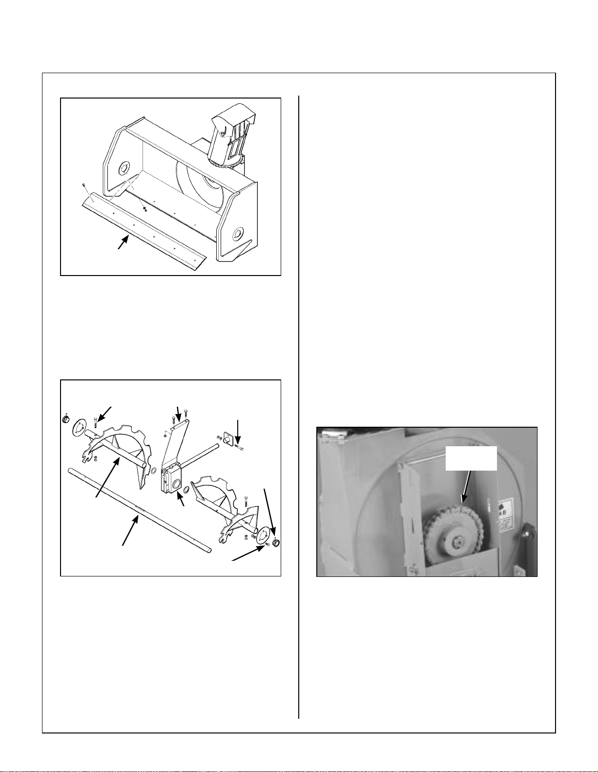
Maintenance Instru ctions REPLACING/REPAIRING
4. Remove the two (2) 5/16-NC nylon locknuts and
the two (2) 5/16-NC x 1-1/4 in. hex bolts fastening the support bracket and gearbox to the
snowblower frame.
5. Hold and move the gearbox/auger assembly to
the left and the right side will slide out. Slide the
left side out.
6. Remove the two (2) 5/16-18 auger s hear bolts
and two (2) 5/16 nuts. Remove augers from
gearbox/shaft assembly.
7. Replace the gearbox by reversing the r emoval
Reversible
Cutting Edge
Snowblower Cutting Edge Replacement
Two-Stage Snowblower Gearbox
Remove and replace the gearbox as follows:
1. Stop the tractor engine, set the parking brake,
and remove the ignition key.
Auger Shear
Bolt
Support
Bracket
Pinion
Shaft
Bolt
procedures.
Two-Stage Snowblower Reduction Chain
The reduction chain should be replaced if, when adjusted properly, it can be pulled away from the front
of the reduction sprocket more than 1/2 the height
of a tooth on the sprocket. Running th e snowblower with a worn chain increases wear on the
sprockets.
1. Remove the 1/4 x 7-1/2 in. bolt, l ock washer,
and nut from the reduction box cover.
2. Remove the box cover from the reduction box.
Collar
Bearing
Screw
Auger
Shaft
Assembly
Replace Snowblower Gearbox
2. Remove the three (3) 5/16 nuts and the three
(3) 5/16 x 3/4 bolts holding th e bearing fl anges
on each end of the snowblower. Loosen the (2)
two set screws on each collar bearing.
3. Remove the 5/16 nut and the 5/16 x 2 hex pi nion shaft bolt.
Gearbox
Bearing Flange Bolt
Reduction
Chain
Remove Reduction Box Cover
3. Turn the reduction box drive shaft until the master link for the chain is accessible.
4. Remove the master link from the chai n and remove the chain from the sprocket.
5. Place the new chain on the sprockets and install
the master link. Install the clip on the master link
properly. The closed end of the clip should
point in the direction of chain travel.
60
Page 61
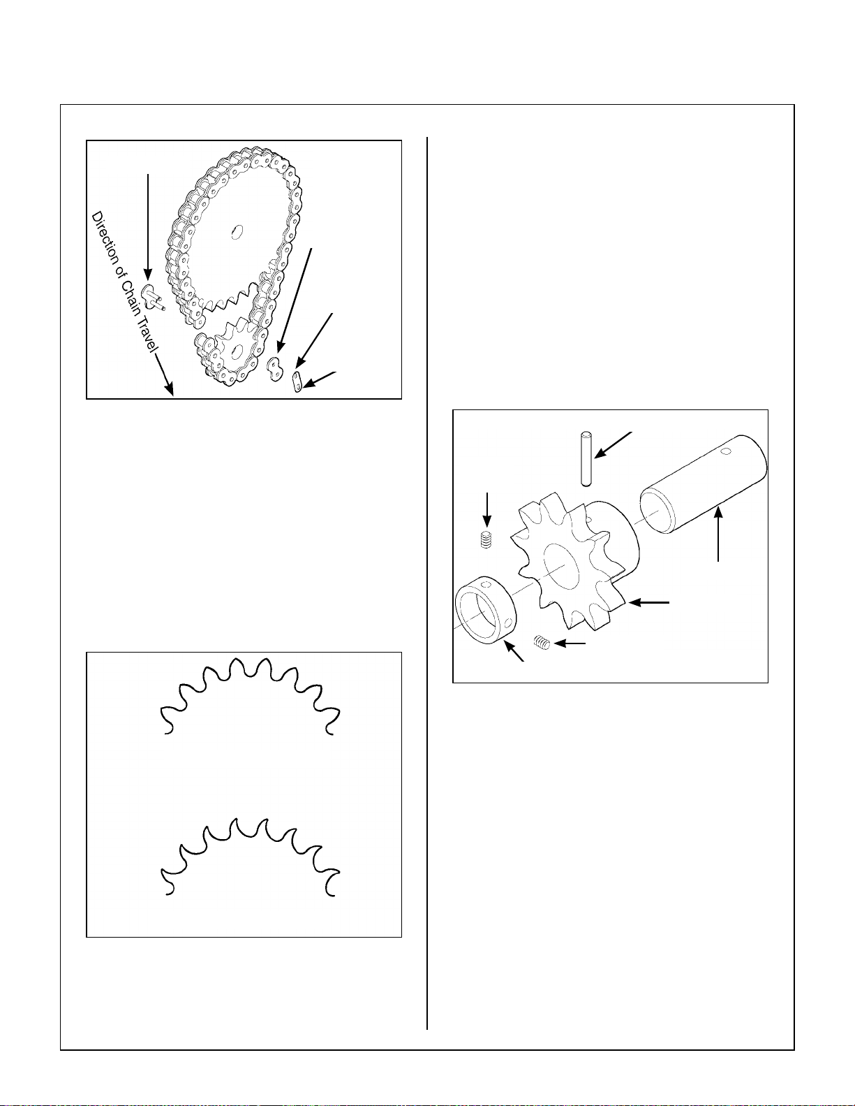
Maintenance Instru ctions REPLACING/REPAIRING
1. Remove the reduction box cover and reduction
Master Link
Plate
Open End
of Clip
chain. Refer to REPLACING/REPAIRING of
Two-Stage Snowblower Reduction Chain in
this section.
2. Loosen the set screws th at fasten the sprock et
to the fan assembly by applying heat to the
thread sealant used on these screws during assembly.
3. Slide the sprocket off the fan asse mbly. Use a
puller if necessary.
Closed End
of Clip
Replace Reduction Chain
6. Adjust the chain tension. Refer to ADJUSTMENTS of Two-Stage Snowblower Reduction Chain Tension in this section.
7. Reinstall the reduction bo x cover by revers ing
the removal procedures.
Two-Stage Snowblower Reduction Sprocket A sprocket shou ld be re place d when the teeth b e-
come asym metric (when the front of a tooth is a dif-
ferent shape than the back side of the tooth).
Symmetric (Acceptable)
4. Position the new sprocket on the fan assembly.
Apply Loctite
fore tightening.
Set
Screw
Locking Collar
Remove and Replace Sprocket
5. Install chain and adjust the chain tension. Refer
to ADJUSTMENTS of Two-Stage Snowblow-
er Reduction Chain Tension in this section.
®
Threadlocker to set screws be-
Roll Pin
Drive Shaft
Sprocket
Set Screw
Asymmetric (Replace)
Reduction Sprocket Wear
NOTE: Generally, a small sprocket wears faster
than a large sprocket.
6. Lubricate the reduction chain. Refer to LUBRI-
CATION of Two-Stage Snowblower Reduction Chain in this section.
7. Reinstall the reduction box c over by reversing
the removal procedures.
Debris Blower Drive Belt
1. Remove the belt guard from the debris blowe r
housing by removing the two (2) cover pins and
hairpins securing it to the housing.
61
Page 62

Maintenance Instru ctions
REPLACING/REPAIRING/
ADJUSTMENTS
2. Loosen the three (3) nuts and three (3) bolts on
lower pulley bearing support and the adjustment nut on the lowe r end of ea ch (2) eyebolts
to release belt tension.
3. Loosen the two (2) set screws securing the upper pulley bearing to the shaft. Unbol t and remove the upper pulley bearing support.
4. Install the new drive belt and reinstall the upper
pulley bearing suppo rt. Secu re t he bea ring o n
the shaft by tightening the two set screws.
5. Adjust the belt tension. Refer to ADJUST-
MENTS of Debris Blower Drive Belt Tension
in this section. Tighten fastene rs sec urely and
reinstall belt guard by reversing the removal
procedures.
Upper
Support Bolts
5. Adjust the rotation pinions as ins truct ed in AD-
JUSTMENTS of Debris Blower Rotation Pinions in this section. Secur ely tighten the set
screw of each stop ring.
Rotation Handle
Upper Stop
Ring
Lower
Stop Ring
Driven Pinion
Drive Pinion
Lower
Support
Bolts
Debris Blower Drive Belt
Debris Blower Rotation Pinions
1. Remove the drive pinion from the r otation ha ndle by loosening the se t screw and pulling off
the pinion.
2. Remove the rotation handle lower stop ring and
pull up on the rotation handle. Loosen set screw
in upper stop ring. Pull rotation handle up out of
work way. Unbolt and remove the driven pinion.
3. Install the new driven pinion and tighten the nut
and bolt securely.
4. Lower the rotation handle back into its original
position and reinstall th e lower stop ring. Position the new drive pinion flush with the shaft and
securely tighten the pinion set screw.
Eyebolt
Debris Blower Rotation Pinions
ADJUSTMENTS
WARNING
DO NOT attempt to make any adjustments
with the tractor engine running. Disengage the PTO clutch, stop the engine, and
remove the ignition key. W ait for all movement to stop before getting off the seat.
Dozer Blade Skid Shoes
Adjust the skid sh oes to allow the required clearance under the blade. On le vel, paved surfaces,
adjust the skid shoes to all ow approxi matel y 1/4 in.
(6 mm) clearance between the cutting edge and the
surface. On uneven or gravel surfaces, allow 1/2
to 3/4 in. (13 to 19 mm) clearance, depending on the
size of the gravel. Ref er to Skid Shoe Height Ad-
justment illustration.
62
Page 63

Maintenance Instru ctions ADJUSTMENTS
1/4 in. (6 mm) Clearance
for Level, Paved Surfaces
1/2 to 3/4 in. (13 to 19 mm)
Clearance for Uneven or Gravel Surfaces
Skid Shoe Height Adjustment
Rotary Broom Brush Leveling
IMPORTANT: The proper level adjustment of
the broom is essential for efficient operation
and life of the bristles. The broom should regularly be adjusted to prevent uneven brush
wear.
1. Extend the parking stands and raise the broom
to the transport position (s o that the bris tles d o
not contact the ground).
Side to Side Level Adjustment
Rotary Broom Gauge Wheels
This adjustment is required for lawn thatching or leaf
raking operations. Height is adjusted to the nearest
1/4 in. (6 mm) by placing spacer sleeves on the upper or lower sides of the stand support. Adjust
height according to type of application. Refer to
Lawn Thatching and Leaf Raking in Operating In-
structions.
Pivot Bracket
Upper Coupler Bolts
2. Loosen the three bolts on the uppe r couple r of
the pivot br acket.
3. Gently lower the broom head until the brush is
parallel to ground level on bot h sides. Pl ace a
block of wood under each side of the brus h to
keep the brush in place.
4. Tighten the three bolts on the upper coupler, remove the wood blocks, and lo wer the br oom to
the ground to make sure the brush is level.
Pin
Spacer
Sleeves
Gauge Wheel Height Adjustment
Hairpin
Gauge
Wheel
Stand
Support
63
Page 64

Maintenance Instru ctions ADJUSTMENTS
Rotary Broom Drive Chain Tension
The drive chain should have 1/4 to 1/2 in. (6 to
13 mm) of slack at midspan. Remove the chain
guard cover to ch eck slack. Adjust the dr ive chain
as follows:
1. Loosen the chain idler nut.
Drive
Chain
Chain Idler
Chain Idler
Nut
Chain Idler Bolt
Chain
Guard
Two-Stage Snowblower Skid Shoes
Adjust the skid sh oes to allow the required clearance under the blade. On le vel, paved surfaces,
adjust the skid shoes to allow 3/16 to 1/4 in. (5 to
6 mm) clea rance bet ween the c utting edge and the
surface. On uneven or gravel surfaces, allow 1/2
to 5/8 in. (13 to 16 mm) clearance, depending on the
size of the gravel. Ref er to Skid Shoe Height Ad-
justment illustration.
3/16 to 1/4 in. (5 to 6 mm)
Clearance for Level, Paved Surfaces
Loosen Chain Idler Nut
2. Position the chain idler s o the chain ha s 1/4 to
1/2 in. (6 to 13 mm) of slack.
3. Retighten the chain idler nut.
4. Recheck the drive chain tension.
1/4 to 1/2 in. (6 to 13 mm)
Slack at Midspan
Chain Idler
1/2 to 5/8 in. (13 to 16 mm)
Clearance for Uneven or Gravel Surfaces
Skid Shoe Height Adjustment
Two-Stage Snowblower Reduction Chain Tension
Adjust the tension on the reduction chain as follows:
1. Loosen the four (4) bolts securing the lower
sprocket support box to the reduction box housing.
2. Position the lower sprocket support box according to the amount of chain tension required.
The chain should have about 1/4 to 1/2 in. (6 to
13 mm) of slack.
3. To increase the chain tension, position the
support box lower. To decrease the chain ten-
sion, position the support box higher.
4. Retighten the four (4) bolts securing the support
box.
64
Proper Drive Chain Tension
Page 65

Maintenance Instru ctions ADJUSTMENTS
Decrease
Chain Tension
Support
Box Bolts
Increase
Chain Tension
Linchpin
Pivot
Bushing
Gauge Wheel
Reduction Chain Tension Adjustment
Debris Blower Front Gauge Wheel
Adjust the gauge wheel height according to surface
condition.
IMPORTANT: The air blast nozzle must clear
the ground at all times.
1. Remove the linchpin from the wheel pivot shaft.
2. Adjust wheel height by placi ng sleeve spacers
either on the upper or lower side of the wheel
pivot bushing. Placing the spacers on the low-
er side increases gauge wheel height. Placing
the spacers on the upper side lowers gauge
wheel height.
3. Reinstall the linchpin when proper gauge wheel
height has been reached.
Gauge Wheel Height Adjustment
Debris Blower Drive Belt Tension
The drive belt deflection must be 1/8 in. (3 mm)
when 6-1/2 to 9 lbf (29 to 40 N) is applied m idway
between the two pulleys.
1/8 in. (3 mm)
6.5 to 9 lbf
(29 to 40 N)
Proper Drive Belt Deflection
1. Remove the belt guard from the debris blowe r
housing by removing the two (2) cover pins and
hairpins securing it to the housing.
2. Loosen the two (2) nuts and bolts on the blower
pulley bearing suppor t and turn the adjus tment
nuts on each side unti l the required tension is
reached. Tighten the fasteners securely and reinstall the belt guard by rev ersing the removal
procedures.
65
Page 66

Maintenance Instru ctions ADJUSTMENTS
Rotation
Handle
Blower Pulley
Bearing
Support Bolts
Upper
Stop Ring
& Set Screw
Adjustment Eye Bolts
Drive Belt Tension Adjustment
Debris Blower Rotation Pinions
The two (2) rotation pi nions should sl ightly contact
each other without any resistance.
1. Loosen the set screw of each stop ring o n the
rotation handle.
2. Keeping the two (2) pinions slig htly in contact
with each other, position the upper stop ring
against the lower support and tighten the screw.
3. Position the lower stop ring close to the lower
support and tighten the set screw. The rotation
handle should rotate freely without excessive
end play.
Debris Blower Rotation Handle
With the rotation pinio ns properly adjusted , the two
(2) stop rings should be pos it ion ed clos e en oug h to
the lower support to allow the r otation handle to r otate freely without excessive end play.
Lower
Support
Lower
Stop Ring
& Set Screw
Debris Blower Rotation Pinions
Rotation
Pinions
& Handle Adjustment
66
Page 67

Maintenance Instru ctions TORQUE SPECIFICATIONS
TORQUE SPECIFICATIONS
67
Page 68

Removal and Storage Instructions
REMOVAL
Removing Attachments from Implement Hitch
Dozer Blade
1. Park the tractor on a level surface and lower the
dozer blade.
WARNING
DO NOT attempt to remove the dozer
blade with the tractor engine running. Disengage the PTO clutch, stop the engine
and remove the ignition key. Wait for all
movement to stop before getting off the
seat.
T o prevent accidental engine starting, disconnect the fuel solenoid w ire [die sel engines] or the spark plug wire(s) [g asoline
engines].
Rotary Broom
1. Park the tractor on a level surface and lower the
rotary broom.
WARNING
DO NOT attempt to remove the rotary
broom with the tractor engine running.
Disengage the PTO clutch, stop the engine and remove the ignition key. Wait for
all movement to stop before getting off the
seat.
T o prevent accidental engine starting, disconnect the fuel solenoid w ire [diesel engines] or the spark plug wire(s) [gasoline
engines].
2. Extend the parking stands to raise the broom to
the transport position (so that the bristles do not
contact the ground).
2. Remove the linchpin from the qui ck hitch latc h
and place the hitch locking lever in the UN-
LOCKED position.
3. Start the tra ctor engine and carefull y back the
tractor away from the blade.
3. Remove the hairpin from the welded sleeve on
the RH side of the broom mounting bracket. Set
the pivot lock pin in the innermost position (it
may be necessary to lift the broom head slightly), and lock in place with the hairpin.
IMPORTANT: Once the broom is fully
remounted, the pivo t lock pin should be set in
its most extended position in order to allow
the broom to follow varying ground contours.
4. Carefully lower the broom so that it rests on the
parking stands.
5. Disconnect the broom driveline from the tractor
PTO shaft and place the driveline on its support
(located on the female hitch).
6. Remove the linchpin from the quick hitch latc h.
Place the hitch locking lever in the UNLOCKED
position.
7. Start the tractor e ngine and carefully bac k the
tractor away from the broom.
68
Detach Blade from Implement Hitch
Page 69

Removal and Storage Instructions
PTO Shaft
Welded Sleeve
Hairpin
Quick Hitch
Lever
Detach Rotary Broom from Implement Hitch
T wo-Stage Snowblower
1. Park the tractor on a level surface and lower the
snowblower.
Pivot
Lock Pin
WARNING
DO NOT attempt to remove the snowblower with the tractor engine running.
Disengage the PTO clutch, stop the engine and remove the ignition key. Wait for
all movement to stop before gett ing off the
seat.
To prevent accidental engine starting, disconnect the fuel solenoid wire [die sel engines] or the spark plug wire(s) [g asoline
engines].
2. Remove the hairpin from the parall el bar a t th e
adaptor end, and remove the parallel bar from
the implement adaptor.
3. Disconnect the driveline from the tractor PTO
shaft.
4. Remove the linchpin from the qui ck hitch latc h
and place the hitch locking lever in the UN-
LOCKED position.
5. Start the tra ctor engine and carefull y back the
tractor away from the snowblower.
PTO Sha f t
Hitch Locking
Lever
Detach Snowblower from Implement Hitch
Debris Blower
1. Park the tractor on a level surface and lower the
debris blower.
WARNING
DO NOT attempt to remove the debris
blower with the tractor engine running.
Disengage the PTO clutch, stop the engine and remove the ignition key. Wait for
all movement to stop before getting off the
seat.
To prevent accidental engine starting, disconnect the fuel solenoid w ire [diesel engines] or the spark plug wire(s) [gasoline
engines].
2. Set the parking stands in the most extended position and lock in place.
3. Disconnect the tractor PTO shaft from the debris blower input shaft.
4. Remove the linchpin from the quic k hitch latch
and place the hitch locking lever in the UN-
LOCKED position.
5. Start the tractor e ngine and carefully bac k the
tractor away from the debris blower.
69
Page 70

Removal and Storage Instructions
PTO Shaft
Quick Hitch
Hitch Locking
Lever
Detach Debris Blower from Implement Hitch
Latch
Parking
Stand
Support Arms
Detach Implement Hitch from Tractor
Removing Implement Hitch from Tractor
IMPORTANT: Detach any a ttached implement
from the hitch before detaching the hitch
from the tractor. Refer to the instruction s for
REMOVAL of Dozer Blade, Rotary Broom,
Two-Stage Snowblower, or Debris Blower in
this section.
1. Park the tractor on a level surface and lower the
implement hitch.
WARNING
DO NOT attempt to remove the implement
hitch with the tractor engine running. Disengage the PTO clutch, stop the engine
and remove the ignition key. Wait for all
movement to stop before getting off the
seat.
To prevent accidental engine starting, disconnect the fuel solenoid wire [die sel engines] or the spark plug wire(s) [g asoline
engines].
END OF SEASON STORAGE
WARNING
NEVER store the tractor with fuel in the
fuel tank inside a building where open
flames or sparks are present. Allow the
engine to cool before storing in any
enclosure.
Implement Hitch
1. Clean the implement hitch thoroughly.
2. Repaint all parts from which paint has worn.
NOTE: Rustproofing or painting every year
will prolong the life of the hitch components
and moving parts.
3. When the implement hitch is dry, lubricate all
moving parts. Apply lubricant liberally to all exposed surfaces to protect against rust.
4. List the replacement parts that will be needed
before the next season.
70
2. Unplug the male connector on the implement lift
wiring harness from the female connector on
the linear actuator.
3. Remove the hitch pins from each support arm
and slide the implement hitch off the support
arms.
5. Store the hitch in a dry place.
Dozer Blade
1. Clean the dozer blade thoroughly.
2. Repaint all parts from which paint has worn.
Page 71

Removal and Storage Instructions
NOTE: Rustproofing or painting every year
will prolong the life of the blade components
and moving parts.
3. When the dozer blade is dry, lubricate all moving parts with SAE 30 engine oil. Apply oil liberally to all exposed surfaces to protect against
rust.
4. Store the dozer blade in a dry place.
Rotary Broom
1. Clean the rotary broom thoroughly.
2. Repaint all parts from which paint has worn.
NOTE: Rustproofing or painting every year
will prolong the life of the broom components
and moving parts.
3. When the rotary broom is dry, lubricate all moving parts. Apply lubricant liberally to all exposed
surfaces to protect against rust.
4. Store the broom on parking stands so tha t the
bristles do not touch the ground.
Debris Blower
1. Clean the debris blower thoroughly.
2. Repaint all parts from which paint has worn.
NOTE: Rustproofing or painting every year
will prolong the life of the debris blower components and moving parts.
3. When the debris blower is dry , lubricate all moving parts. Apply lubricant liberally to all exposed
surfaces to protect against rust.
4. List the replacement parts that will be needed
before the next season.
5. Store the debris blower in a dry place.
5. If the broom bristles are e xp osed to direct sunlight, protect the bristles with a tarp.
6. List the replacement parts that will be needed
before the next season.
7. Store the broom in a dry place.
Two-Stage Snowblower
1. Clean the snowblower thoroughly.
2. Repaint all parts from which paint has worn.
NOTE: Rustproofing or painting every year
will prolong the life of the sn owblower components and moving parts.
3. When the snowblower is dry, lubricate all moving parts. Apply lubricant liberally to all exposed
surfaces to protect against rust.
4. List the replacement parts that will be needed
before the next season.
5. Store the snowblower in a dry place.
71
Page 72

IMPLEMENT HITCH ASSEMBLY
ITEM PART DESCRIPTION NO.
NO. NO. REQ’D
Implement Hitch
1 6627 PTO Shield 1
2 I392 Safety Chain Assembly 1
I015 Chain 1
O/L 5/16 Linchpin 1
O/L 5/32 x 1 Cotter Pin 1
3 5588 Rubber Bumper 1
4 I001 Quick Hitch 1
6625-1 Hitch Assembly, Male 1
5 O/L 9/16 ID Flat Washer 1
6 6621 Linear Actuator (11-3/4) 1
7 6630 Hitch Lift Crank 1
8 6621-1 Clevis Pin (1/2 x 2) 2
9 6624 Mounting Frame Assembly, Hitch 1
10 6618 Decal, Hitch Mount Adjust 1
11 6626 Pivot Shaft 1
12 5830-3 Grease Fitting (45 Degree) 2
13 5830 Grease Fitting 1
14 I393 Decal, Attaching Hitch 1
15 O/L 3/8-NC Nylon Locknut 1
16 I002 Quick Hitch Latch 1
17 O/L 3/8-NC x 1-1/2 Hex Bolt 1
18 O/L 3/32 x 3/4 Cotter Pin 1
19 I009 Attaching Lever 1
20 7860 Handle Grip 1
21 I005 1/4 x 1-11/16 Pin 1
22 NS Spring Plate (RAD 657383) 1
ITEM PART DESCRIPTION NO.
NO. NO. REQ’D
23 I008 Spring (1/4 x 1) 1
24 7822 Decal, PTO Shield 1
Fasteners
F002 10-24 Keps Nut 1
F005 1/4-20 ESNA Nut 2
F027 10-24 x 5/8 PPHMS 1
F036 1/4-20 x 1/2 SBH Screw 2
F068 1/8 x 1 Cotter Pin 6
F212 3/4-10 x 2 Hex Bolt 1
F213 3/14-10 Nut 1
NOTE: Decals are illustrated in greater detail in the Owner ’s sec-
tion of this manual. Refer to SAFETY, CONTROL, AND
INSTRUCTION DECALS in Safety Instructions, Page
17.
NOTE: All NS items are listed with a RAD Part Number (e.g., RAD
657383), and are not sold by Walker Manufacturing. To
order these items, contact:
RAD Technologies Inc.
2835, Chemin de l’Aéroport
Thetford Mines (Québec)
G6G 5R7 CANADA
1-418-338-4499
72
Use only genuine Walker® replacement parts. Effective Date 06-01-01
Page 73
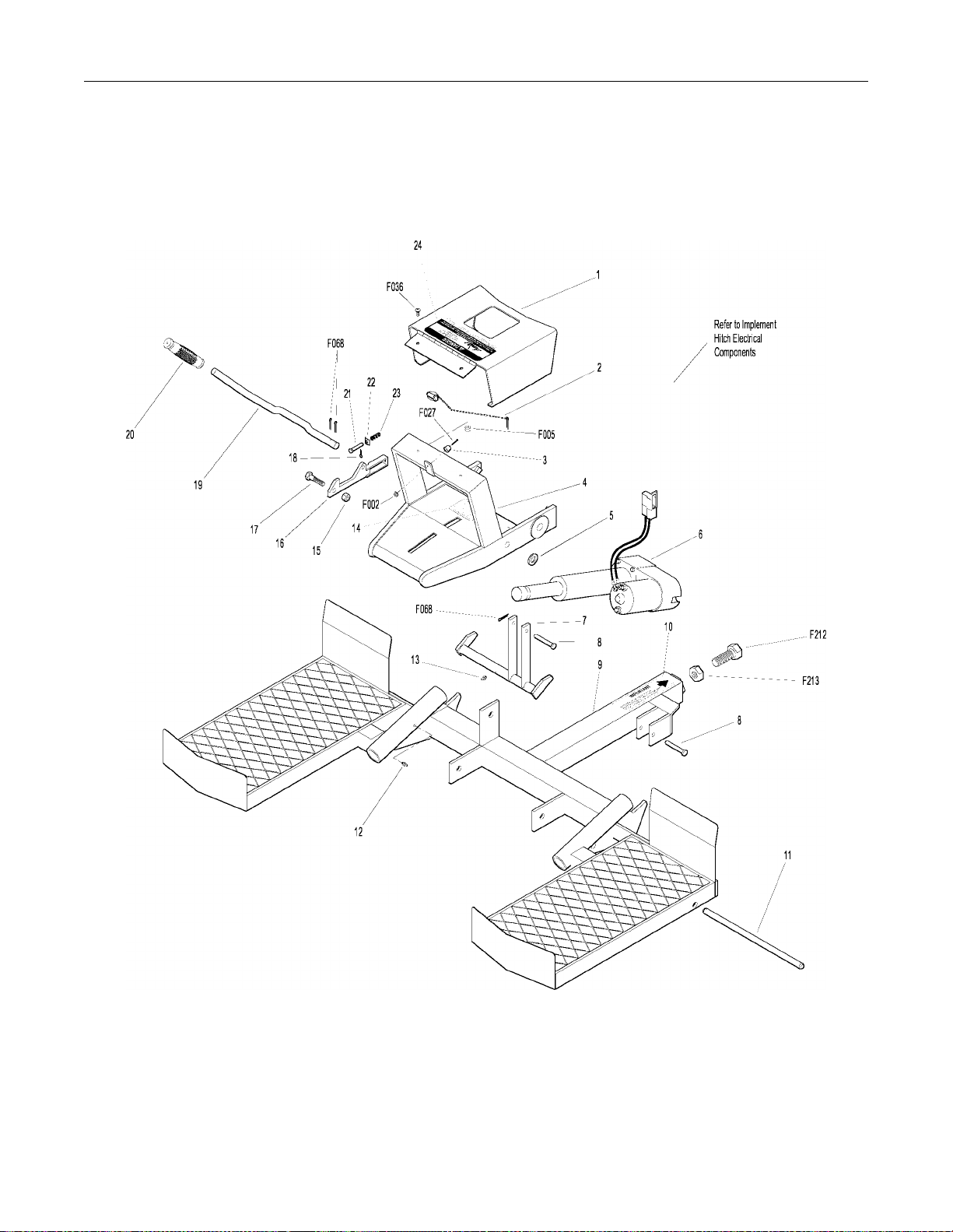
IMPLEMENT HITCH ASSEMBLY
Effective Date 06-01-01 Use only genuine Walker® replacement parts.
73
Page 74

IMPLEMENT HITCH ELECTRICAL COMPONENTS
ITEM PART DESCRIPTION NO.
NO. NO. REQ’D
Implement Hitch Electrical Components
1 6623-1 Switch Boot (Fits P/N 6623) 1
2 6628 Switch Mount Bracket 1
3 6623 Lift Control Switch 1
4 6632 Decal, Implement Hitch 1
5 5832 Cable Clamp (1/2) 3
6 6622 Wiring Harness, Actuator 1
6631 Implement Hitch Electrical Package
*
ITEM PART DESCRIPTION NO.
NO. NO. REQ’D
Fasteners
F002 10-24 Keps Nut 5
F025 10-24 x 3/8 PPHMS 3
F026 10-24 x 1/2 PPHMS 2
* Service Part Only
NOTE: Decals are illustrated in greater detail in the Owner ’s sec-
tion of this manual. Refer to SAFETY, CONTROL, AND
INSTRUCTION DECALS in Safety Instructions, Page
17.
NOTE: All NS items are listed with a RAD Part Number (e.g., RAD
657383), and are not sold by Walker Manufacturing. To
order these items, contact:
RAD Technologies Inc.
2835, Chemin de l’Aéroport
Thetford Mines (Québec)
G6G 5R7 CANADA
1-418-338-4499
74
Use only genuine Walker® replacement parts. Effective Date 06-01-01
Page 75

IMPLEMENT HITCH ELECTRICAL COMPONENTS
Effective Date 06-01-01 Use only genuine Walker® replacement parts.
75
Page 76

DOZER BLADE ASSEMBLY
ITEM PART DESCRIPTION NO.
NO. NO. REQ’D
Dozer Blade Assembly
1 I061 Spring (1-7/8 x 9) 1
2 I064 Pivot Pin 1
3 I060 1/4 x 1 Roll Pin 2
4 I065 Adjustment Pin 1
5 I063 Female Quick Hitch 1
6 NS Decal, Trip Spring Lockout (RAD 657503) 1
7 I058 Hitch Box 1
8 I059 3/4 x 17-3/4 Pin 1
9 5800 Decal, Walker Mower (4 x 7-1/2) 1
10 NS Decal, Stay Clear Blade (RAD 657524) 2
11 I050 Welded Blade 1
12 O/L 5/16-NC Hex Nut 7
13 O/L 5/16 Lock Washer 1
14 I056 Skid Shoe Pin 2
15 I055 Skid Shoe 2
16 I057 3mm x 65mm Hairpin 3
17 O/L 5/16-NC x 1 Carriage Bolt 6
18 I051 Cutting Edge 1
19 I068 Trip Spring Lockout Pin 1
20 I067 Trip Spring Lockout 1
ITEM PART DESCRIPTION NO.
NO. NO. REQ’D
21 I341 5/16-18 x 5 Eyebolt 1
(Includes Item # 11)
Fasteners
F317 3/16 x 1 Split Spring Pin 1
NOTE: Decals are illustrated in greater detail in the Owner ’s sec-
tion of this manual. Refer to SAFETY, CONTROL, AND
INSTRUCTION DECALS in Safety Instructions, Page
17.
NOTE: All NS items are listed with a RAD Part Number (e.g., RAD
657383), and are not sold by Walker Manufacturing. To
order these items, contact:
RAD Technologies Inc.
2835, Chemin de l’Aéroport
Thetford Mines (Québec)
G6G 5R7 CANADA
1-418-338-4499
76
Use only genuine Walker® replacement parts. Effective Date 06-01-01
Page 77

DOZER BLADE ASSEMBLY
Effective Date 06-01-01 Use only genuine Walker® replacement parts.
77
Page 78

ROTARY BROOM ASSEMBLY
ITEM PART DESCRIPTION NO.
NO. NO. REQ’D
Rotary Broom Assembly
1 I385 Stand Support Bracket 2
2 I366 Parking Stand 2
3 NS Housing (RAD 661579) 1
4 663827 Clevis 1
5 O/L 5/16-NC Hex Bolt, Plated 1
6 I377 Chain, 3/16 x 15 1
7 I347 Tension Spring 1
8 I344 Clevis 1
9 I341 5/16-18 x 5 Eyebolt 1
10 7860 Handle Grip 1
11 NS Adjustment Handle (RAD 663640) 1
12 I057 3mm x 65mm Hairpin 1
13 I306 Stopper Pin, 1/2 x 2-9/16 1
14 I329 Pivot Bracket 1
15 I339 Upper Bushing 1
16 O/L 7/16-NC x 1-3/4 Hex Bolt 1
17 I171 11/32 Nylon Washer 1
18 I170 5/16-18 Knob 1
19 NS Upper Coupler (RAD 661009) 1
20 I328 Female Hitch 1
21 O/L 7/16-NC x 1-1/4 Hex Bolt 1
22 O/L 5/16-NC x 1 Hex Bolt 2
23 I343 Driveline Support 1
24 O/L 3/32 x 3/4 Cotter Pin 2
25 O/L 5/8 Uni-Torque Nut 1
26 O/L 5/16-NC Nylon Locknut 2
27 O/L 3/8 ID Flat Washer 2
28 O/L 7/16 Nylon Locknut 1
29 O/L 1/2 ID Flat Washer 1
30 O/L 7/16 Lock Washer 1
31 O/L 7/16-NC Hex Nut 1
32 I338 Adjustment Plate 1
33 I348 Torsion Spring 1
34 O/L 1/2 Nylon Locknut 2
35 O/L 9/16 ID Flat Washer 2
36 I367 Pivot Bushing 2
37 5830 Grease Fitting 4
38 I364 11/16 Nylon Washer 4
39 I317 Wheel Cap 4
40 I312 Wheel Bushing 4
41 I310 Bearing 4
42 I311 Plastic Wheel (4") 2
43 O/L 1/4 x 1-1/4 Cotter Pin 2
44 I335 Wheel Bracket, RH 1
I336 Wheel Bracket, LH 1
ITEM PART DESCRIPTION NO.
NO. NO. REQ’D
45 O/L 1/2-NC x 3-1/2 Hex Bolt 2
46 O/L 5/16-NC x 1/4 Set Screw 2
47 O/L 4mm x 80mm Hairpin 2
48 O/L 5/32 x 1-1/4 Cotter Pin 2
49 O/L 5/16-NC x 1/2 Hex Bolt (Flange) 4
50 O/L 1/2-NC Nylon Hex Nut 2
51 O/L 1/2-NC x 1-3/4 Hex Bolt 2
52 O/L 5/16-NC Hex Nut 1
Kit I391 Side Caster Wheels Kit
Includes Items listed below and instructions. Side Caster Wheel
Kit is not shown here. May be ordered as a factory-installed option
or as a kit for dealer installation. Contact your Walker dealer.
NS Locking Screw (RAD 663527) 2
O/L 5/16-NC Flange Nut 8
NS Right Bracket (RAD 663532) 1
Left Bracket (RAD 663533) 1
O/L 5/16-NC x 3/4 Flange Bolt 8
NS Support (RAD 663534) 2
NS Wheel Bracket, RH (RAD 663535) 1
Wheel Bracket, LH (RAD 663536) 1
O/L 11/16 ID Flat Washer 8
I319 Wheel, 6 x 2 2
O/L 1/4 x 1-1/2 Cotter Pin 2
I364 0.063 ID Nylon Ring 2
O/L 3/16 x 1-1/2 Cotter Pin 2
NS Decal, Brush Height (RAD 661521) 2
Fasteners
F317 3/16 x 1 Split Spring Pin 1
NOTE: Decals are illustrated in greater detail in the Owner ’s sec-
tion of this manual. Refer to SAFETY, CONTROL, AND
INSTRUCTION DECALS in Safety Instructions, Page
17.
NOTE: All NS items are listed with a RAD Part Number (e.g., RAD
657383), and are not sold by Walker Manufacturing. To
order these items, contact:
RAD Technologies Inc.
2835, Chemin de l’Aéroport
Thetford Mines (Québec)
G6G 5R7 CANADA
1-418-338-4499
78
Use only genuine Walker® replacement parts. Effective Date 06-01-01
Page 79

ROTARY BROOM ASSEMBLY
Effective Date 06-01-01 Use only genuine Walker® replacement parts.
79
Page 80

ROTARY BROOM DRIVE COMPONENTS
ITEM PART DESCRIPTION NO.
NO. NO. REQ’D
Gearbox Assembly
1 NS Dipstick Plug (RAD 661741) 1
2 O/L M8 x 45 Bolt 8
3 NS Casing (RAD 661740) 1
4 NS Oil Seal (RAD 661730) 3
5 NS Snap Ring (RAD 661734) 3
6 NS 25.6 x 0.6 Shim (RAD 661733) 1
7 NS Bearing (RAD 661732) 2
8 NS 25.6 x 0.7 Shim (RAD 661731) 1
9 NS Pinion, 29M3.5 (RAD 661735) 1
10 NS Gear Z25M35 (RAD 661738) 1
11 NS Bearing 6205 (RAD 661728) 2
12 O/L M8 Hex Nut 8
13 O/L 3/8-NC x 5 Hex Bolt 4
14 NS Shaft (RAD 661729) 1
15 NS Parallel Key, A8 x 7 x 25 (RAD 660063) 1
16 NS 25.6 x 0.8 Shim (RAD 661737) 1
17 NS 25.6 x 1.0 Shim (RAD 661736) 1
18 NS 3/8 Plug (RAD 661739) 1
19 NS O-Ring (RAD 661144) 1
20 O/L 3/8 Lock Washer 1
21 O/L 3/8 Hex Nut 1
ITEM PART DESCRIPTION NO.
NO. NO. REQ’D
38 O/L 5/16-NC x 3/4 Set Screw 1
39 I162 1/4 x 1/4 x 1 Key 1
40 O/L 5/16-NC x 5/8 Set Screw 1
41 I387 Chain Idler 1
42 I388 Spacer 1
43 O/L 7/16 ID Flat Washer 1
44 O/L 3/8-NC x 2 Hex Bolt 1
45 I397 Decal, Safety Procedures 1
46 O/L 5/16-NC x 1/4 Set Screw 2
47 I305 1/4 x 1/4 x 1-1/4 Key 1
48 I390 Brush Drive Shaft 1
49 I376 Gearbox, Updated Broom 1
(Includes Items # 1-21)
50 NS Decal, Important - Avoid Damage 1
(RAD 660328)
51 NS Decal, Grease All Points (RAD 658708) 1
52 NS Decal, Brush Ground Contact 1
(RAD 661052)
53 I389 Brush Support Adaptor 1
54 5800 Decal, Walker Mower (4 x 7-1/2) 1
55 I386 Polypropylene Brush, 1 piece 1
NS Brush, 50% Steel / 50% Nylon
(RAD 661727)
*
Driveline and Sprockets Assembly
22 6651 Driveline Male Portion Assembly 1
(Includes Items # 23-27)
23 6651-3 Bearing Retainer 1
24 6651-2 Nylon Bearing 1
25 I395 Decal, Rotating Driveline 1
26 6651-1 PTO Outer Shield 1
27 6651-4 Male Shaft and Yoke Assembly 1
28 I378 Chain Drive Shaft 1
29 I120 Bearing Flange 6
30 5609 Bearing (with Set Screw) 3
(Includes Item # F309)
31 O/L 5/16 Lock Washer 9
32 O/L 5/16-NC Hex Nut 9
33 I381 Chain, #40 x 71 Links 1
34 NS Connecting Link #40 (RAD 656153) 1
35 I382 Chain Guard 1
36 O/L 5/16-NC x 3/4 Carriage Bolt 9
37 I380 Drive Sprocket 40B36 1
Fasteners
F309 1/4-28 x 1/4 Set Screw 3
* Service Part Only
NOTE: Decals are illustrated in greater detail in the Owner ’s sec-
tion of this manual. Refer to SAFETY, CONTROL, AND
INSTRUCTION DECALS in Safety Instructions, Page
17.
NOTE: All NS items are listed with a RAD Part Number (e.g., RAD
657383), and are not sold by Walker Manufacturing. To
order these items, contact:
RAD Technologies Inc.
2835, Chemin de l’Aéroport
Thetford Mines (Québec)
G6G 5R7 CANADA
1-418-338-4499
80
Use only genuine Walker® replacement parts. Effective Date 06-01-01
Page 81

ROTARY BROOM DRIVE COMPONENTS
Effective Date 06-01-01 Use only genuine Walker® replacement parts.
81
Page 82

SNOWBLOWER HOUSING COMPONENTS
ITEM PART DESCRIPTION NO.
NO. NO. REQ’D
Chute Rotation Assembly
1 NS Chute, Base and Knobs (with Decals) 1
(RAD 661168)
2 I396 Decal, Keep Hands Out 1
3 I172 7/16 Nylon Washer 2
4 O/L 5/16-NC x 1 Carriage Bolt 2
5 I175 Hand Guard 1
6 O/L 1/4-NC Hex Nut 12
7 O/L 1/4 Lock Washer 12
8 O/L 5/16 ID Flat Washer 2
9 O/L 1/4-NC x 3/4 Hex Bolt 2
10 7860 Handle Grip 1
11 I188 Handle (with Grip) 1
12 O/L 1/4-NC x 1 Allen Socket Head Cap Screw 1
13 O/L 1/4-NC Nylon Locknut 2
14 O/L 1/4-NC x 1/2 Hex Bolt 6
O/L 1/4-NC x 3/4 Hex Bolt 2
15 I187 Support Rotation 1
16 I186 1-11/16 Plastic Bushing 1
17 I185 Rotation Worm 1
18 I183 Nylon Ring 1
19 I180 Retaining Plate 4
20 I184 1-5/16 Plastic Bushing 1
21 O/L 5/16-NC Nylon Locknut 2
22 I170 5/16-18 Knob 2
23 I171 11/32 Nylon Washer 2
24 I397 Decal, Safety Procedures 1
ITEM PART DESCRIPTION NO.
NO. NO. REQ’D
Reduction Box Assembly
35 I196 PTO Guard 1
36 I163 40 x 38 Chain 1
37 NS Reduction Box (RAD 657355) 1
38 I153 Drive Shaft (with Sprocket), H40C11 1
39 I120 Bearing Flange 4
40 5609 Spindle Bearing & Collar 2
(Includes Item # F309)
41 I305 1/4 x 1/4 x 1-1/4 Key 1
42 O/L 5/16-NC Hex Nut 14
43 O/L 5/16 Lock Washer 14
44 O/L 5/16-NC x 5/8 Carriage Bolt 6
45 O/L 1/4-NC x 2-1/2 Hex Bolt 1
46 O/L 3/8 ID Flat Washer 8
47 O/L 5/16-NC x 3/4 Carriage Bolt 10
48 O/L 1/4-NC x 7-1/2 Hex Bolt 2
49 I162 1/4 x 1/4 x 1 Key 1
50 O/L Set Screw (5/16-NC x 1/2, Allen) 2
51 I161 Sprocket (H40B32) 1
Snowblower Frame Assembly
52 I125 Skid Shoe 2
53 O/L 5/16-NC x 1 Carriage Bolt 4
54 I122 Cutting Edge 1
55 O/L 5/16-NC Stover Nut 6
56 NS Frame (RAD 661031) 1
Snowblower Mount Assembly
25 6621-2 Clevis Pin (1/2 x 2) 2
26 6670-2 Parallel Bar Assembly 1
Fasteners
F068 1/8 x 1 Cotter Pin 2
F309 1/4-28 x 1/4 Set Screw 2
27 6670-1 Snowblower Mount Assembly (Female) 1
28 O/L 3/8-NC x 1 Hex Bolt 2
29 O/L 1/2-NC x 1 Hex Bolt 2
30 O/L 1/2 Lock Washer 2
31 O/L 1/2-NC Hex Nut 2
NOTE: Decals are illustrated in greater detail in the Owner ’s sec-
tion of this manual. Refer to SAFETY, CONTROL, AND
INSTRUCTION DECALS in Safety Instructions, Page
17.
32 O/L 7/16 ID Flat Washer 2
33 O/L 3/8 Lock Washer 2
34 O/L 3/8-NC Hex Nut 2
NOTE: All NS items are listed with a RAD Part Number (e.g., RAD
657383), and are not sold by Walker Manufacturing. To
order these items, contact:
RAD Technologies Inc.
2835, Chemin de l’Aéroport
Thetford Mines (Québec)
G6G 5R7 CANADA
1-418-338-4499
Use only genuine Walker® replacement parts. Effective Date 06-01-01
82
Page 83

SNOWBLOWER HOUSING COMPONENTS
Effective Date 06-01-01 Use only genuine Walker® replacement parts.
83
Page 84

SNOWBLOWER DRIVE COMPONENTS
ITEM PART DESCRIPTION NO.
NO. NO. REQ’D
Gearbox Assembly
1 I193 Double Lip Seal 2
2 NS Breather, 3/8 NPT & O-Ring (Comer) 1
(RAD 661185)
NS Pressure Plug, 1/8 NPT (Usimax) 1
(RAD 654927)
3 O/L M8 Hex Nut 6
4 I178 Spring Pin, Casing 2
5 NS Cap (RAD 661150) 1
6 I182 Bearing, Gearbox 2
7 NS Pinion Gear (RAD 661160) 1
8 I198 Shim, Pinion Shaft 1
9 I194 Oil Seal 1
10 I199 Shaft, Gearbox 1
11 O/L M8 x 40 Hex Bolt 2
12 O/L M8 x 65 Hex Bolt 4
13 NS Casing Ello (RAD 661145) 1
14 NS Oil Plug, 1/4 (Comer) (RAD 661972) 1
NS Plug, 1/8 NPT (Usimax) (RAD 656090) 1
15 I195 Bearing 2
16 I181 Shim, Gearbox 2
17 NS Gear (RAD 661159) 1
18 NS Plug, 3/8 NPT & O-Ring (Comer) 1
(RAD 659847)
NS Plug, 1/8 NPT (Usimax) (RAD 656090) 1
19 NS Casing (RAD 661142) 1
Driveline and Auger Components
20 6671 Driveline Male Portion Assembly 1
(Includes Items # 25-29)
21 I394 Decal, Rotating Auger 2
22 5800 Decal, Walker Mower (4 x 7-1/2) 1
23 NS Decal, Check Oil Level (RAD 655683) 1
24 NS Decal, Lubricate Chain (RAD 657804) 1
25 6671-4 Male Shaft and Yoke Assembly 1
26 6671-3 Bearing Retainer 1
27 6671-2 Nylon Bearing 1
28 6671-1 Outer Shield 1
29 I395 Decal, Rotating Driveline 1
30 5609 Spindle Bearing & Collar 2
(Includes Item # F309)
31 O/L 5/16-NC Hex Nut 12
ITEM PART DESCRIPTION NO.
NO. NO. REQ’D
32 O/L 5/16 Lock Washer 12
33 I120 Bearing Flange 2
34 O/L 5/16-NC x 3/4 Carriage Bolt 3
35 NS Decal, Use Shear Bolts (RAD 657346) 1
36 I103 Bushing 2
37 O/L 5/16-NC x 2 GR 8 Hex Bolt 1
38 I109 Auger, LH 1
39 I111 5/16-18 x 2-1/4 Shear Bolt Lock & Nut 2
40 I128 Shear Bolt Bushing 4
41 I113 Bearing Flange 2
42 O/L 3/8 ID Flat Washer 2
43 5830 Grease Fitting 2
44 I101 Gearbox (Comer) 1
(Includes Items # 1-19)
NS Gearbox (Usimax) (RAD 663030) 1
NS Seal Kit (RAD 665775) 1
45 NS Output Shaft (RAD 657286) 1
46 I130 Woodruff Key 1
47 I110 Auger, RH 1
48 O/L 5/16-NC x 3/4 Hex Bolt 8
49 NS Gearbox Support Bracket (RAD 657332) 1
50 I105 1/4-20 x 1 Shear (w/Locknut) 1
51 I104 Fan Adaptor Shear Plate 1
52 I102 Fan Assembly 1
Fasteners
F309 1/4-28 x 1/4 Set Screw 3
NOTE: Decals are illustrated in greater detail in the Owner ’s sec-
tion of this manual. Refer to SAFETY, CONTROL, AND
INSTRUCTION DECALS in Safety Instructions, Page
17.
NOTE: All NS items are listed with a RAD Part Number (e.g., RAD
657383), and are not sold by Walker Manufacturing. To
order these items, contact:
RAD Technologies Inc.
2835, Chemin de l’Aéroport
Thetford Mines (Québec)
G6G 5R7 CANADA
1-418-338-4499
84
Use only genuine Walker® replacement parts. Effective Date 06-01-01
Page 85

SNOWBLOWER DRIVE COMPONENTS
Effective Date 06-01-01 Use only genuine Walker® replacement parts.
85
Page 86

DEBRIS BLOWER COMPONENTS
ITEM PART DESCRIPTION NO.
NO. NO. REQ’D
Debris Blower Components
1 I402 Impeller Housing 1
2 NS Impeller (RAD 662644) 1
3 NS 1-14 Castel Nut (RAD 654988) 1
4 O/L 3/16 x 2 Cotter Pin 3
5 NS Intake Cover (RAD 662646) 1
6 O/L 5/16-NC Flange Nut 23
7 5830 Grease Fitting 1
8 NS Cap (RAD 662825) 2
9 NS Wheel Support Spacer (RAD 662737) 1
10 O/L 5/16 Linchpin 1
11 O/L 5/8-NC x 5-1/2 Hex Bolt 1
12 O/L 1/4-NC x 1 Hex Bolt 8
13 NS Wheel Support (RAD 662642) 1
14 O/L 5/8-NC Locknut 1
15 NS Wheel Spacer (RAD 662822) 2
16 I426 Wheel and Tire Assembly 1
17 NS Rotation Spacer (RAD 661498) 4
18 NS Rotation Bracket (RAD 663096) 1
19 O/L 1/4 Lock Washer 8
20 O/L 1/4-NC Hex Nut 8
21 I186 Plastic Bushing, 1-11/16 2
22 NS Worm (RAD 663503) 1
23 NS Retaining Plate (RAD 661508) 1
24 I183 Nylon Ring 1
25 NS Air Blast Nozzle (RAD 662672) 1
26 I172 7/16 ID Nylon Flat Washer 2
27 O/L 5/16-NC x 3/4 Carriage Bolt 1
28 I170 Knob, 5/16-18 1
29 NS Deflector (RAD 662734) 1
30 O/L 11/32 Nylon Flat Washer (RAD 658467) 1
31 O/L 5/16-NC Nylon Locknut 1
32 O/L 5/16-NC x 1 Carriage Bolt 1
33 NS Parking Stand (RAD 662648) 2
34 NS Cover Pin, 1/4 x 1/2 (RAD 662926) 2
35 O/L Hairpin, 5/64 x 1-5/8 (2mm x 41mm) 2
36 NS Belt Cover (RAD 662735) 1
37 I439 Shaft, 1 x 7-3/8 1
38 O/L 7/16-NC Hex Nut 4
39 O/L 7/16 Lock Washer 4
ITEM PART DESCRIPTION NO.
NO. NO. REQ’D
40 I452 Bearing 1
41 NS Upper Bearing Support (RAD 662713) 1
42 O/L 5/16-NC x 1 Carriage Bolt 2
43 O/L 7/16-NC x 1-1/4 Hex Bolt 4
44 NS V-Belt AM33 (RAD 663458) 1
45 I162 Key, 1/4 x 1/4 x 1 2
46 I461 Pulley MA38 1
47 NS Key, 1/4 x 1/4 x 2-1/2 (RAD 660924) 1
48 I459 Shaft, 1 x 12-11/16 1
49 I120 Flange Bearing 6
50 NS Housing (RAD 662643) 1
51 O/L 7/16 ID Flat Washer 4
52 O/L 3/8 Lock Washer 4
53 O/L 3/8-NC x 2 Hex Bolt 2
54 NS Eyebolt Spacer (RAD 663043) 2
55 NS 5/16-NC x 4 Eyebolt (RAD 663273) 2
56 O/L 5/16-NC Nylon Locknut 2
57 NS Snap Button (RAD 663601) 2
58 NS Lower Brg Support, Ext (RAD 663296) 1
59 5609 1" Brg w /Locking Collar 3
60 NS Pulley MA53 (RAD 663457) 1
61 O/L 5/16-NC x 3/4 Carriage Bolt 9
62 NS Lower Brg Support, Int (RAD 663382) 1
63 O/L 3/8-NC x 1-1/4 Carriage Bolt 2
64 O/L 5/16-NC x 1-1/4 Carriage Bolt 2
NOTE: Decals are illustrated in greater detail in the Owner ’s sec-
tion of this manual. Refer to SAFETY, CONTROL, AND
INSTRUCTION DECALS in Safety Instructions, Page
17.
NOTE: All NS items are listed with a RAD Part Number (e.g., RAD
657383), and are not sold by Walker Manufacturing. To
order these items, contact:
RAD Technologies Inc.
2835, Chemin de l’Aéroport
Thetford Mines (Québec)
G6G 5R7 CANADA
1-418-338-4499
86
Use only genuine Walker® replacement parts. Effective Date 06-01-01
Page 87

DEBRIS BLOWER COMPONENTS
Effective Date 06-01-01 Use only genuine Walker® replacement parts.
87
Page 88

DEBRIS BLOWER MANUAL ROTATION COMPONENTS
ITEM PART DESCRIPTION NO.
NO. NO. REQ’D
Debris Blower Manual Rotation Components
1 7860 Handle Grip 1
2 NS Rotation Handle (RAD 663509) 1
3 5830 Grease Fitting 2
4 O/L #8-32 x 1/8 Allen Set Screw 2
5 O/L 1/4-20 x 3/16 Allen Set Screw 2
6 I415 Drive Sprocket 1
7 I403 Driven Sprocket 1
8 I186 1-11/16 Plastic Bushing 2
9 O/L 1/4-NC Nylon Locknut 1
10 NS Rotation Worm (RAD 663503) 1
11 O/L 1/4-NC x 1-1/4 Hex Bolt 1
12 NS Adjustment Bushing (RAD 663332) 2
13 I412 Handle Rotation Guide 1
14 O/L 5/16-NC Flange Nut 2
ITEM PART DESCRIPTION NO.
NO. NO. REQ’D
15 I406 Handle Fixation Bracket 1
NOTE: Decals are illustrated in greater detail in the Owner ’s sec-
tion of this manual. Refer to SAFETY, CONTROL, AND
INSTRUCTION DECALS in Safety Instructions, Page
17.
NOTE: All NS items are listed with a RAD Part Number (e.g., RAD
657383), and are not sold by Walker Manufacturing. To
order these items, contact:
RAD Technologies Inc.
2835, Chemin de l’Aéroport
Thetford Mines (Québec)
G6G 5R7 CANADA
1-418-338-4499
88
Use only genuine Walker® replacement parts. Effective Date 06-01-01
Page 89

DEBRIS BLOWER MANUAL ROTATION COMPONENTS
Effective Date 06-01-01 Use only genuine Walker® replacement parts.
89
Page 90

KEY TO ABBREVIATIONS USED IN ILLUSTRATED PARTS MANUAL
Abbreviation What it Represents
º (Dimension ) .................... .. ............. .. .. .............. .. .. ............. ... ............. .. .. .............. .. ..........Degrees (Angle)
" (Dimension ) ................. ... ............. .. .. .............. .. .. ............. .. .............. .. .. ............. ... ............................inches
cfm.............................................................................................................................cubic feet per minute
cl..................................................................................................................................................centiliters
cm.............................................................................................................................................centimeters
Dba ............................................................................................................................................... Decibels
DC...................................................................................................................................... .. .Direct Cu rrent
ESNA (Fastener) ....................................................................................................... Nylon Insert Locknut
fl. oz. ..................................................................................................................................... ..fluid ounces
FSC........................................................................................................................Forward Speed Control
ft............................................................................................................................................................ feet
ft-lb...........................................................................................................................................foot-pounds
GHS...................................................................................................................... Grass Handling System
GR (Fastener) . .................................................................................................................................. Grade
HP.......................................................................................................................................... Horse Power
ID..............................................................................................................Identification or Inside Diameter
kg.................................................................................................................................................kilograms
km/h or kph...................................... .. .............. .. .. ............. .. .............. .. .. ............. ... ....... kilometers per hour
kPa.............................................................................................................................................kilopascals
lb.....................................................................................................................................................pounds
lbf........................................................................................................................poundals or pounds force
LH..........................................................................................Left Hand (orientated with operator on seat)
m......................................................................................................................................................meters
mm (Dimensio n ) .... ............. .. .. ............. ... .. ............. .. .............. .. .. ............. .. .............. .. .. ...............millimeters
mph...................................................................................................................................... miles per hour
N................................................................................................................................................... Newtons
NC (Fastner)..................................................................................................................... National Coarse
NF (Fastner) ..........................................................................................................................National Fine
NPT........................................................................................................................... National Pipe Thread
NS (as part number) .................................................................. Item is not sold by Walker Manufacturing
N·m .....................................................................................................................................Newton-meters
O/L................................................................... Obtain Locally (Item is not sold by Walker Manufacturing)
P/N..........................................................................................................................................Part Number
PPHMS (Fastener) ...............................................................................Phillips Pan Head Machine Screw
PSI..............................................................................................................................Pounds Square Inch
PTO.................................................................................................................................... Power Take-Off
RH....................................................................................... Right Hand (orientated with operator on seat)
RPM.........................................................................................................................revolutions per minute
SAE (Fastener).......................... .................................... .. .. .....................Society of Automotive Engineers
SBH (Fastener) ..................................................................................................Socket Button Head (Bolt)
S/N....................................................................................................................................... Serial Number
U......................................................................................................................................................Unified
90
NOTE: In some instances, combinations of abbreviations may be used (e.g. UNC - Unified National Coarse).
Use only genuine Walker® replacement parts. Effective Date 06-01-01
Page 91

LIMITED W ARRANTY
FOR
WALKER
COMMERCIAL RIDER MOWER
1. WHAT THIS WARRANTY COVERS, AND FOR HOW LONG:
Walker Manufacturing company will, at its option, repair or replace, without charge, any part covered by this warranty
which is found to be defective in material and/or workm anship within one (1) year* after date of sale to the original retail
purchaser unless the product is used for rental purposes, in which case this warranty is limited to ninety (90) days. At
Walker's request, customer will make the defective part available for inspection by Walker and/or return the defective part
to Walker, transportation charges prepaid. All parts and components of the Walker Mower are covered by this warranty
except the following components which are warranted separately by their respective manufacturers:
Kohler Engine
Kubota Engine
Kawasaki Engine
Eaton Hydraulic Transmission
Peerless Gearboxes
Battery
Tires
The available warranties covering these items are furnished with each mower. Walker does not assume any warranty obligation, liability or modification for these items, which are covered exclusively by the stated warranty of the respective manufacturers noted above.
* An extended three (3) year warranty is offered on the Walker P/N 6200-7 Gear Axle Assembly.
2. WHAT THIS WARRANTY DOES NOT COVER:
A. This warranty does not cover defects caused by depreciation or damage caused by normal wear, accidents, improper
maintenance, improper use or abuse of the product, alterations, or failure to follow the instructions contained in the
Owner’s Manual for operation and maintenance.
B. The customer shall pay any charges for making service calls and/or for transporting the mower to and from the place
where the inspection and/or warranty work is performed.
3. HOW TO OBTAIN SERVICE UNDER THIS WARRANTY:
Warranty service can be arranged by contacting the dealer where you purchased the mower or by contacting Walker Manufacturing Company, 5925 East Harmony Road, Ft. Collins, CO 80528. Proof of the date of purchase may be required to
verify warranty coverage.
4. WARRANTY LIMITATION:
A. THERE IS NO OTHER EXPRESS WARRANTY. ANY WARRANTY THAT MAY BE IMPLIED FROM THIS
PURCHASE INCLUDING MERCHANTABILITY AND FITNESS FOR A PARTICULAR PURPOSE IS HEREBY
LIMITED TO THE DURATION OF THIS WARRANTY AND TO THE EXTENT PERMITTED BY LAW ANY AND ALL
IMPLIED WARRANTIES ARE EXCLUDED. Some states do not allow limitations on how long an implied warranty
lasts, so the above limitations may not apply to you.
B. WALKER WILL NOT BE LIABLE FOR ANY INCIDENTAL, CONSEQUENTIAL, OR SPE CIAL DAMAGES AND/OR
EXPENSES IN CONNECTION WITH THE PURCHASE OR USE OF THE MOWER. Some states do not allow the
exclusion or limitation of incidental or consequential damages, so the above limitation(s) or exclusion(s) may not
apply to you.
C. Only the warranty expressed in this limited warrant y shall apply and no dealer, distributor, or individual is authorized
to amend, modify, or extend this warranty in any way. Accordingly, additional statements such as dealer advertising
or presentations, whether oral or written, do not constitute warranties by Walker, and should not be relied upon.
D. This warranty gives you specific legal rights, and you may also have other rights which vary from state to state.
91
Page 92

WALKER MFG. CO. • 5925 E. HARMONY ROAD, FORT COLLINS, CO 80528 • (9 70) 221-5614
FORM NO. 060101 PRINTED IN USA ©2001 WALKER MFG. CO
www.walkermowers.com
 Loading...